| | |||
| Mini Table Saw | |||
| | |||
| Mini Table Saw | |||
| Back to Table Saw Stuff | Build Info | Plywood Ripper | Mitering Plywood |
Occasionaly I need table saw accuracy on small projects.
I looked at some of the commercially available small (4") table saws: Byrnes Table Saw (too expensive), and the Harbor Freight Mini (too cheap).
Blades for the above were limited and pricey.
Before I had a table saw, I built what I called a "Plywood Ripper", which consisted of a circular saw mounted, upside down, on a tee track on the side of my woodworking bench.
The tee track on the workbench is there for clamping long or wide pieces to the side of the bench.
I used this to cut out all the pieces for the first 4" dust collector plenum and updraft valves, which worked great.
After thinking about it, I decided to make a small table saw like the Plywood Ripper for cutting smaller pieces of wood.
The plywood ripper used a conventional 7-1/4" circular saw, mounted upside down.
I have a number of 7-1/4" blades already.
The only critical part of making this small table saw is making sure the blade is parallel to the rip fence.
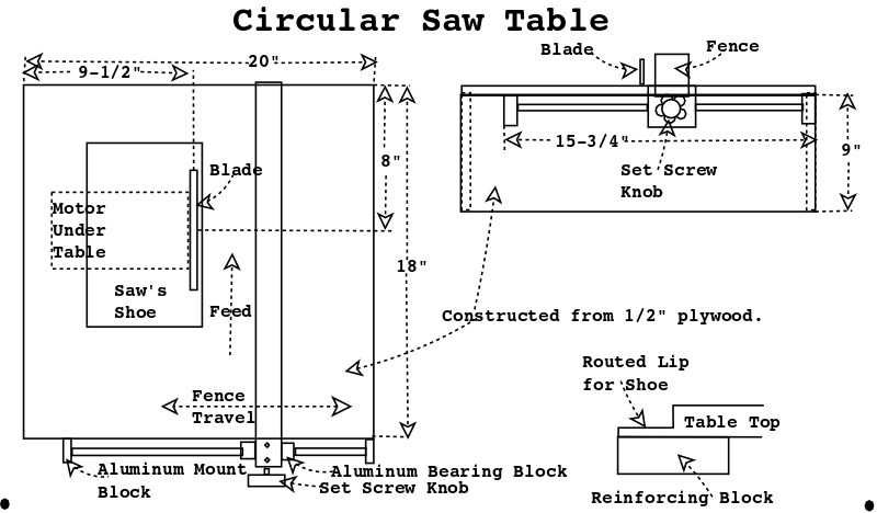
This small table saw (MiniTableSaw) will be a 20" X 18" box with a circular saw mounted upside down and a wooden rip fence mounted on a linear motion rod. The 1/2" plywood was left over from other projects. One interesting todo, I need to countersink the saw's shoe so it is flush with the table top. Because I'm using 1/2" plywood and countersinking the shoe 3/8", I'll need to glue reinforcment strips beneath the periphery of the shoe. The linear motion rods and the inexpensive 7-1/4" saw I bought from Amazon. The 400mm linear motion rods (2 to a package) came with four aluminum bearing blocks (I'll only need 1 to mount the fence end) and 4 aluminum mount blocks, this should keep the fence parallel to the saw blade. I'll drill and tap a hole in the aluminum bearing block for a set screw with knob. The linear motion rod I bought came 2 in a pack (making it $11.00 ea.), but I didn't want to use two tee tracks with tee knobs and have measure both ends for each cut, I'll save the second one for another project. I used a 120Volt SPST toggle switch from my junk box and reused the cord from the circular saw.
The 9-1/2" height sitting on my 36" work bench is OK, I like my work a little closer to my face anyway. I'll put a 4" dust port in one side with several 1/2"quot; holes drilled on the opposite side so I get a good "sweeping" action inside. I think I can do this without destroying the saw, the handle and switch are held on with screws.
|
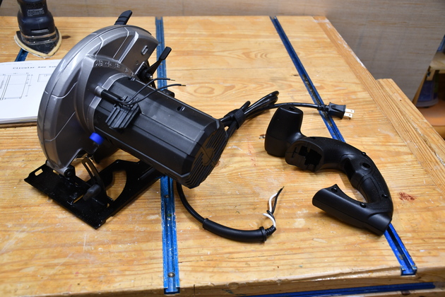
The inexpensive saw with it's handle, cord, and switch removed. |
|
This is the way it will be mounted in the MiniTableSaw. Note, you are looking at the saw's "shoe", this is what I have to counter sink so it is flush with the table. |
|
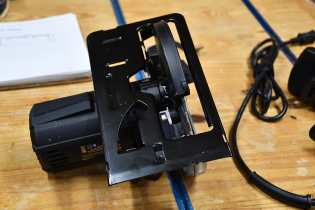
Another angle on the saw and it's shoe, note the angled lip at the front of the shoe. |
|
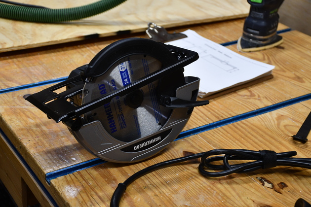
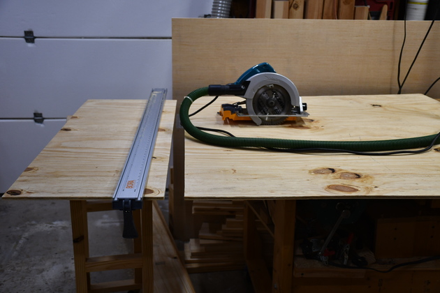
Sizing a sheet of plywood. Here I'm using a Makita 7-1/4" |
|
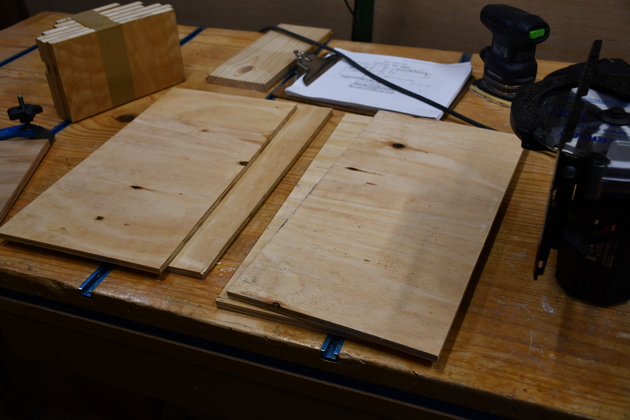
Plywood sides and ends. |
|
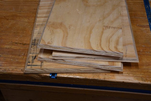
Mitered edges of MiniTableSaw case. I'll make this box gluing the mitered edges together. The top will be glued last to keep the sides square. |
|
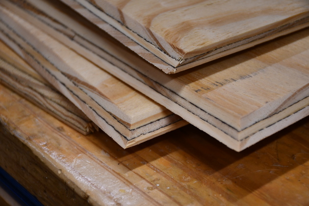
Closer look at mitered plywood edges. |

|
Hole for saw's shoe cut in table top. This is before I mitered the table top's edges so it will fit neatly on top of the cabinet sides. The table top is 1/2" oak plywood, the sides are pine. |
|
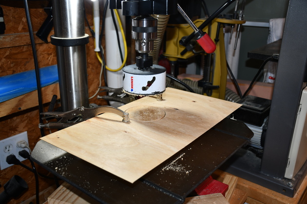
Sawing 4" hole for dust collector port. |
|
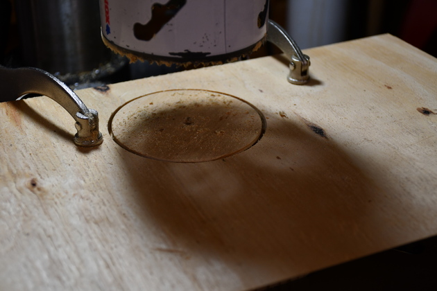
Closer look at hole sawing operation. |
|
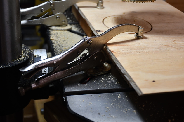
I found these Drill Press Clamps years ago at Harbor Freight, they are great for clamping things to the drill press bed. I don't remember what I paid, but they are $9.00 ea. in 2020. Note they work like vice-grips, with approximately 1/2" (probably 12mm) bolt and nut. |
|
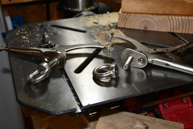
This is what the drill press clamps look like not clamped to the bed. You can see the ring nut which acts as a nut and washer with a handle to tighten/loosen. |
|
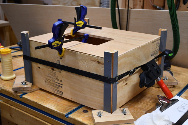
The MiniSawTable cabinet in my 6" "Clamping Cauls". You can't see it but behind the Bessy clamp handle, is a 4" hole for air intake, I'll put a sliding door over it (like my router box on the router table) so I can control how much air is let in. I built these years ago, and have built many many boxes/cabinets with them since. I ultimately made 3 sets, 6", 12", and 24" high. The two Irwin clamps are to keep the sides from bulging. |
|
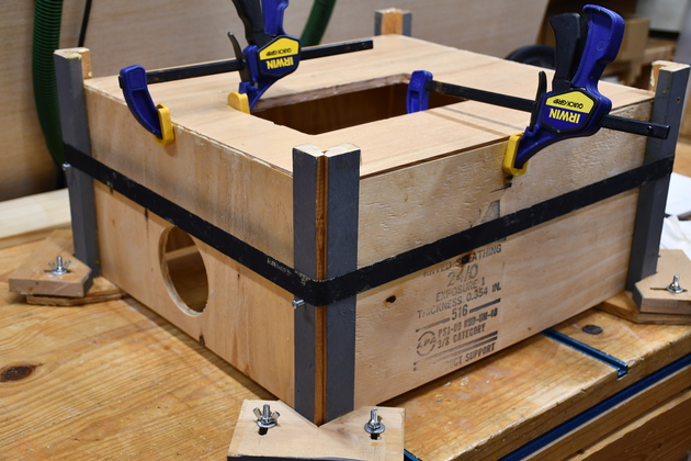
From this perspective you can see the dust port. One of the nice things about making boxes this way, is when you put the top on, it forces the sides to be square. |
Linear Bar
|
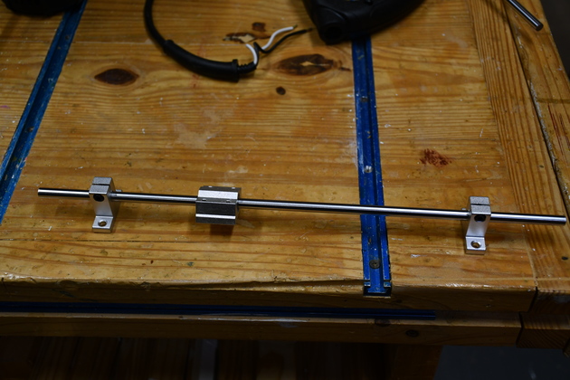
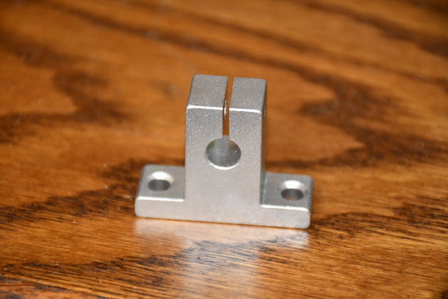
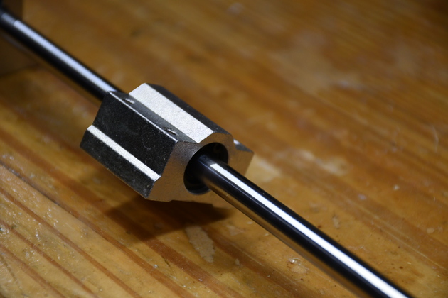
One of the linear bars with mounts and bearing block. |
|
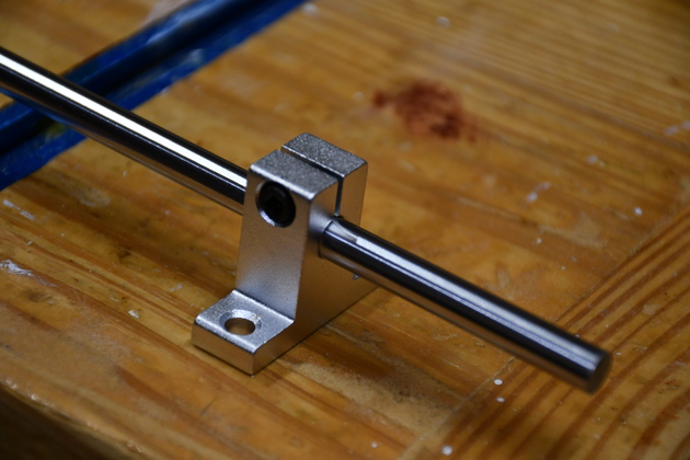
Closer look at a mount.
|
|
One of the mounting blocks. |
|
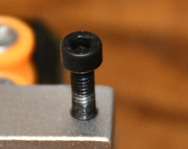
I've moved the bolt to the other side of the block so we can see the allen socket better. The 3mm diameter allen socket is about 2mm in depth, not much to grap hold of when really plutting a lot of pressure trying to tighten or loosen the bolt. You can tell by looking at the end threads of the screw, thats aluminum deposited on the threads because of the high pressure. And we all know how easily aluminum threads strip! |
|
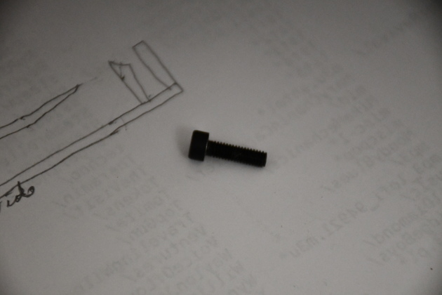
The 3mm x 15mm allen cap screw. You can see it has a standard square shoulder. |
|
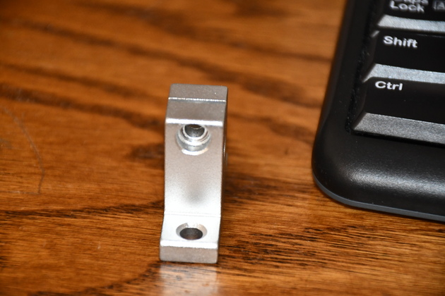
Looking at the coutersunk hole for the head of the allen cap screw, in the mounting block. It is difficult to tell in this pic but the shoulder of the countersink is beveled?? I realze you need some aluminum below the cap screw head to push against. But, had this shoulder been cut square, the builders could have used a cap screw with a little bit deeper allen socket. I know this looks great, but they could even have used a hex head bolt and not counter sunk at all. |
|
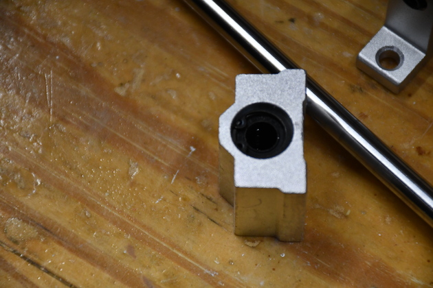
Bearing block on the linear position bar. |
|
There appear to be 4 rows of ball bearing, you can see the end ball on two rows here. |

|
|