System Board |
Current Sensor |
240V Blower Switch |
Terminal |
DustAuto Controller |
4" Updraft Valve | 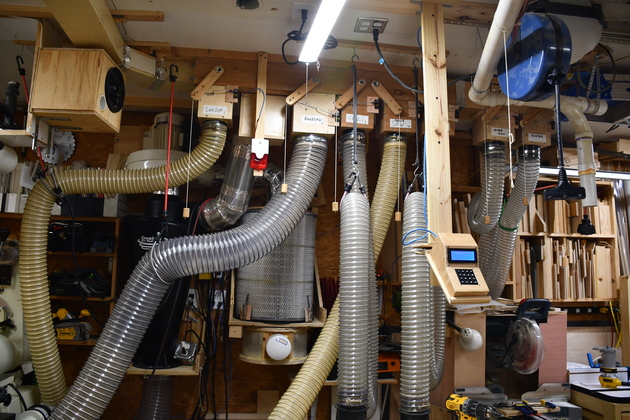
Main 6" plenum |
4" Slider Valve |
|
Dust Collector Automation
| |||
|
System Board |
Current Sensor |
240V Blower Switch |
Terminal |
|
DustAuto Controller |
4" Updraft Valve |
Main 6" plenum |
4" Slider Valve |
|
Dust Collector Automation
| |||
Over the years I have built up a decent 6" dust collector, based on a Jet DC-1200 blower,
Oneida Super Dust Deputy XL Cyclone, Wynn Environmental filter, home built plenum, 4"
and 6" updraft valves, and one high pressure 4" slider valve.
In 2021, I upgraded the blower (motor and impeller) to the Jet DC-1200.


I also have a dust detector on the dust bin to shutdown the system when the bin becomes full.
I iniatially tried ultrasonic dust detection which worked OK if the top of the
dust is flat, however, cyclones tend to have a cone shaped dust pile, as the
pile gets deeper, which reflects the ultrasonic pulses at angles so the bin
sometime appears to be several yards deep.
In other words, ultrasonic detectors are unreliable for cyclones.
So I am trying an infrared obstacle avoidance module.


This approach can also be used in automating almost anything where you need to
start an electric motor when a current is sensed.
In recent years, I have been considering automating the DC (Dust Collector). In the spring of 2020 (during the Covid-19 pandemic), after reading several articles and watching several videos I decided to automate my larger dust collection system. One site I found particularly interesting and got several ideas from was I Like To Make Stuff One note: Bob's shop's dust ducting had a tree structure with more than one valve to reach a specific machine, making it a sightly more complicated system. My system has a one dedicated valve per machine which made my task a little simpler.
I really like the 2" dust collector's (CT-22) feature of automatically turning on the DC when a connected tool is turned on, so I will encorporate it into the automation.
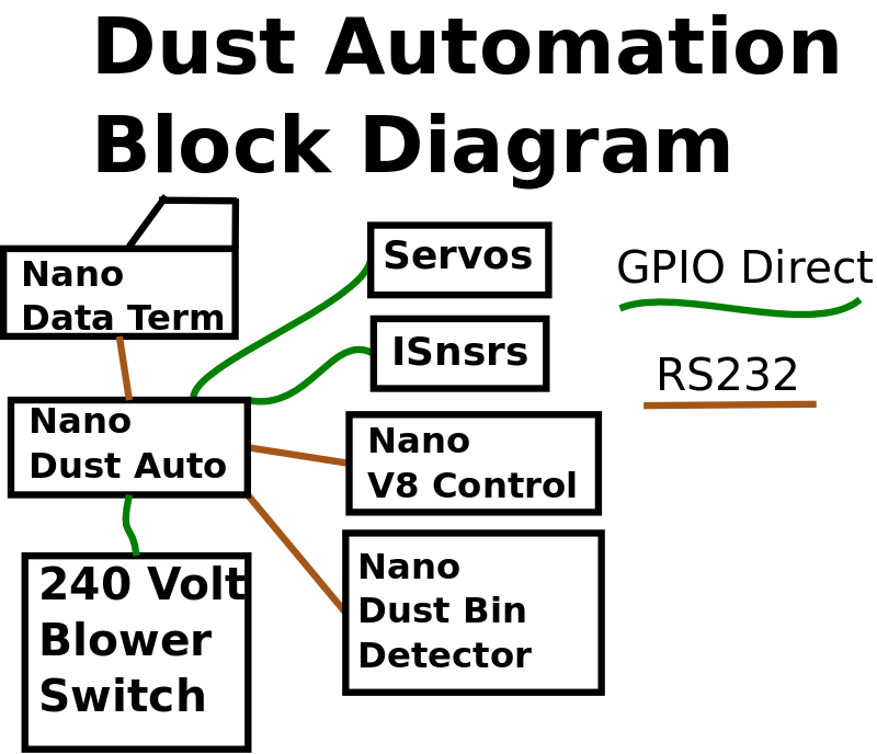
By Automation I mean computer control of dust valves, the blower, sensing machine motor current, and dust bin space. The system will sense when a machine motor is turned on (monitor it's current), configure the system (open the proper dust valve, closing all others), and turn on the DC's blower. When the machine is turned off, allow the dust in the plenum to be flushed out, stop DC's blower, then close the valve. I also have two valves I use for my lathe, vacuuming up the shop, and my jointer, so I need a way to manually control the system. Please see the DataTerminal page. Valve 8 is used for 3 devices, two of which (planer and spindle sander) are connected to V* current sensor, and the dovetail jig's router (not connected to an I sensor). While I'm thinking about it, I'll incorporate dust bin monitoring into the system, and maybe vacuum pressure display!
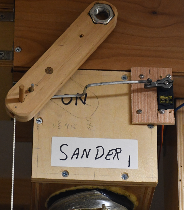
My updraft valves are very easy to automate since it takes very little force to open/close them when the blower is off, an MG996 works fine and relatively small movement distance. One thing to note about my updraft valves is, by design, they are very difficult to open or close while the blower is running. One of my original design goals was: air flow tends to keep the valve open and vacuum tends to keep it closed, and the weight and gravity acts like a memory.
Real-Time Control System
Servos don't move instantaneously and motors don't start or stop instantaneously so when an action is desired the controller issues a command to the hardware then waits for that to complete before issuing another command.
In other words, there are mechanical constraints on when the controller acts.
In most cases, the Dust Auto system only does one action at a time, so the power supply stays constant.
I will build this as a modular system, in order to simplify debugging, possible future modifications, etc.
Now that almost all hardware issues are resolved, and quoting my good friend Lee Blanton, it is now SMOP (Simply a Matter Of Programming).
Communication:
The dust auto system uses RS232 protocol @ 9600 baud to communicate with it's sub servers.
The system is organized as follows: Dust Auto (DA) is the main controller, with 3 external Nano computers, Data Terminal, Dust Detector, and Valve-8.
The Data Terminal uses asynchronous communication with DA, and may send or receive characters at any time.
DA sends a request to the Dust Detector and waits for a reply (OK or FAIL).
DA sends an open or close command to Valve-8 and waits for a reply (OK or FAIL).
DA is always listening on its primary UART for the Data Terminal.
DA uses Software Serial to communicate with the other remote servers (Dust Detector, and Valve-8), hence it is a request response system, DA listens for a fixed time for the response and reports any timeouts as failures.
One of the really nice things about RS232 control, is you can plug each of the small systems or controllers here directly into the Arduino IDE and debug it.
Added an environment sensor to the system which constantle monitors the temperature and humidity in the shop and externally. This is another request/response type of comm with DA via V8.
I have a little experience with Arduino and some of it's minions, I thought this would be fun and handy to have.
I'm even thinking about automating my 2" system and it's slide valves.
In automating the dust collection system I need to be able to sense when one of my power tools is running (and which one) in order to select the correct dust valve and start the DC.
Historically the way to do this is by sensing the current drawn by the machine's motor.
I also have some valves that aren't conncected to a specific tool, like the floor sweep hose which are also used when I use my lathe.
I need a manual mode so I can tell the system to open a valve and start the DC then Cancel the operation (stop the DC and close the valve) when I'm finished.
Electronics page and the Data Terminal page .
I am going to monitor the current drawn by each particular machine using a current sensor (ACS712), an analog multiplexer (Mux), and the Nano's ADC (Analog To Dital Converter) Input. Because the Nano has 8 analog inputs, but 2 are required for I2C, and I may need as many as 8, I'll use an analog mux (multiplexer) to scan the current sensors. Other current sensing projects, on YouTube, integrate the ACS712 for almost a second to arrive at the RMS value of the current. I don't like having to integrate analog readings for several cycles @60Hz, polling some thing that slow is less than expeditious (ugly), even phone line polling is faster. The ACS712 has a 2.5V DC offset, and it's output is a very low amplitude (66mv/Amp) at a 60 Hz sinewave. The low amplitude signal in a electrically noisy environment (large AC motors running) is problematic and the offset doesn't help. So I'll AC couple (reference signal to ground), amplify and rectify it's output, (no integration time), a short sample time will work. This doesn't have to be super accurate, I just need to differentiate when the motor is running and when not. In some cases I'll need to ignore things like a work light on my miter saw and bandsaw so a base line may be needed. I'll also need a manual way to start the DC since I have two "free" hoses I use to clean the floor and with the lathe. Please take a look at the Isensor Page.
I am going to use MG996 servos, since I am familiar with them, to open/close my updraft valves.
Valve #8 will need to be able to open under pressure due to the planer, I'll need to create a new high pressure slide valve for it.
In order to drive 8 servos I'll use the PCA9685 I2C 16 channel PWM servo drivers.
In order to read multiple device currents, I'll use an analog multiplexer (MUX).
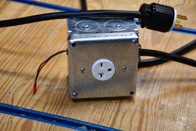
Original Power Switch
After hearing Bob Clagett's comments about his DC relay failing, I went straight to a trusted part.
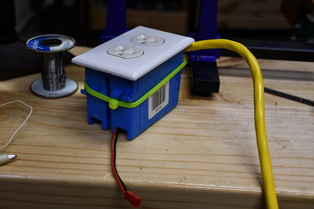
I'll need a SPST (Single Pole Single Throw) switch that will handle 120 Volt @ < 20Amps without welding itself.
I'm using a Solid State Relay (SSR) from Amazon to control the DC Blower.
These SSRs are $10.74 and switch 40Amps AC at 24 - 480 VAC, you can get some cheaper for lower current.
I could have gotten something a little cheaper, but I knew this works and I want reliability.
These things work great with a 5 volt DC (Direct Current) input signal and a tiny bit of current (about 10MA) input.
This SSR will switch 120/240 Volts @ 40 Amps on or off (it can tolerate the blower motor's back EMF), so they're ideal for an Arduino switching a fair sized inductive load (lika a motor).
Please see my Blower Switch page for more info.
Blower Upgrade (2020)
During the COVID_19 pandemic, I upgraded the blower (and it's power switch).
08/04/20:
The system is fully functional and stable, I really enjoyed my first major electronics project in many years.
I am getting too old (eyesight) to deal with these crimp connectors, even though I have a decent crimper, so I ordered male/female extender cables and spliced in a longer center segment to get the length I need.
I did go a little overboard on the Isensors I didn't want to spend lots of time scanning Isnsrs since the Nano has lots more going on.
So far the Isnsrs are stable, even the 240Volt sensor for the table saw and the Nano scans all 8 quickly, about 30Ms per sensor, for a total of 240Ms.
The current reading is averaged for almost two 60Hz cycles (30MS) in case I get a little pulsating DC out of the filter.
If I have problems with the Isensors I have an add-on discriminator (using the other half of the LM358) that should solve any problems.
The add-on has a higher threshold, more gain, and hysteresis.
I did consider several ideas about controlling and displaying information about the system, Bob Clagett, on his first attempt, used a 9 key keypad, but only used tool motor current sensing in his second.
Long long ago I designed and used small data terminals to control systems, and I have a great appreciation for the flexibility they provide.
Recently, I have done a little robotics work and decided to make an Arduino, Data Terminal.
The sysem doesn't normally need a lot of current (2 Amp supply works OK), but I had problems when the power glitched (off then quickly back on), the PCA9685 apparently tried to move a lot of servos at once, a 4 Amp supply would crowbar (go into current limiting) and the system would go into oscillation.
So I used a more robust 5 Volt, 8 Amp power supply, the problem has not manifested itself since.
You might notice in the code, when I sense the miter saw is running I set a timer so the DC will run for 20 seconds before shutdown.
When I am sizing pieces on a project, the miter saw is only on for a short bursts of time, I don't want the Dust Collection system to be constantly trying to start and stop.
12/02/20 Dust Detector problem.
When the dust bin nears being full, the dust detector can't seem to see the dust pile.
I'm working on a new design of the Dust Detector using an active IR detector.
06/01/21
The system has been in operation for about a year and all is stable, no glitches except for the dust bin sensor, which has been stable ever since I switched to IR.
|
|
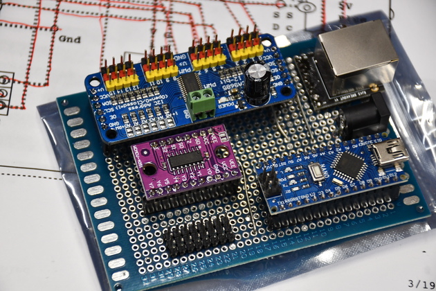
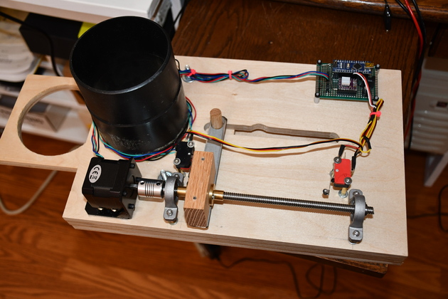
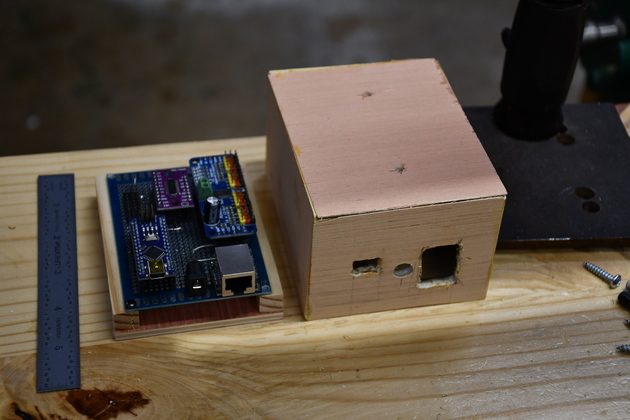
The system controller board. The board at the top (black/red/yellow connectors) is the servo controller board (PCA9685). The purple board on the left is the analog mux, (74HC4051), the row of connectors below it are for the current sensor inputs. The Nano is lower right. RJ-45 to data terminal is upper right. The black thing between the Nano and the RJ-45 is the 5V power input receptical. After this was taken, I added two 4 wire flat cables, one to the DustDetector, and the other to valve 8 (planer valve). |
|
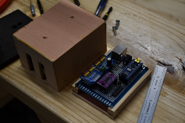
Here it is, mounted on it's base with the cabinet beside it. You can see the holes, in the cabinet's front, for the RJ-45, power, and USB for programming the Nano. Thats a 6" ruller to the left of the controller. |
|
Different perspective showing the input/output cable slots in the back of the case. |
|
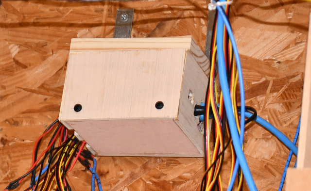
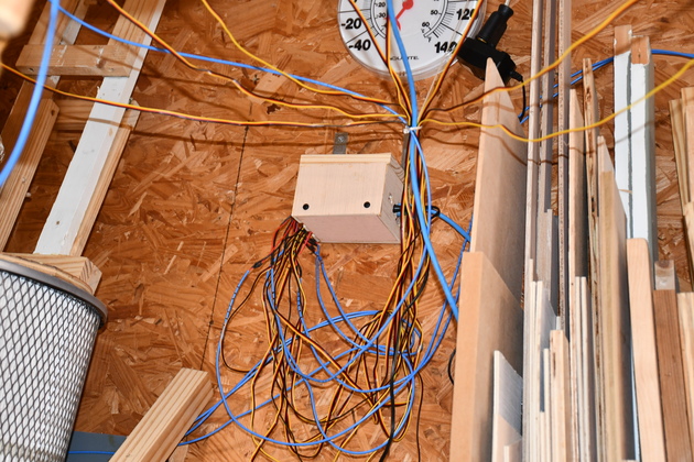
The system controller mounted high on the West wall. Yes, it's a rat's nest. The yellow.red.brown cables are outputs to the servos, the blue wires are the current sensor inputs. One more blue wire is the DCgo signal to the power switch for the Dust Collector. |
|
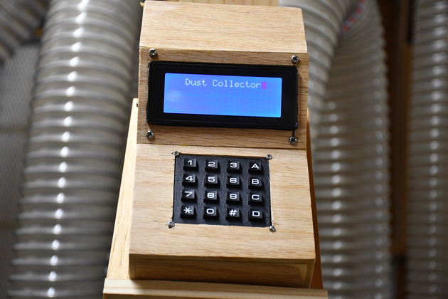
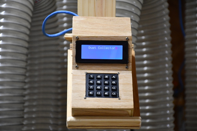
The data terminal showing the system is in IDLE mode, awaiting a command or a motor start. |

|
Dust Detector2 mounted under the filter shelf, the 4 wire flat cable brings power from the control box and RS232 between the two systems. The 3 wire flat cable provides power and contact with the actual dust sensor. You can also see system Isensors #1, and #2 on the left. |

|
Dust Detector sensor mounted in the top of the dust bin. There is an HC-SR04 looking straight down into the dust pile. Of course, when the DC is running there is a lot of swirling dust in the bin so it gets false readings, the Dust Collector System has to filter these out. |

|
|