01/08/21: Page Origin
The Environment Server monitors temperature, humidity, and air compressor pressure in the shop and in it's attic.
The environment readings are stored in static variables, updated every 2sec.
The Env server will be on the shop's RS-485 buss.
The ShopGwy will be the gateway from our in-house network to the shop and be visible to all internal network systems.
I added the shop internal info to our weather page, the Dust Auto system will be able to display current temp/humidity inside and outside on it's data terminal.
The next project a programmable thermostat for the shop's Senville mini-split will be accessable from our in-house network.
And in addition I could add some checks for shop occupancy, like with a PIR detector, or ultrasonic check to see when the overhead door is open.
It would also be handy to have a presence indicator, with audible alert, on both porches.
Look at live answer from the Shop Gateway
Originally the shop gateway was run on an Rpi-3, but due to UART configuration stability problems, I built one based on a Nano with an Ethernet Module.
I evaluated Arduino Ethernet interfaces, and settled on a W5500 Ethernet Module.
The ENC28J60 was cheap and is a Nano shield, but the library (UIPEthernet) used so much dynamic memory, the program ovreran it creating instability!
Some ethernet interfaces had their own 3.3V voltage regulator, others required you to supply the 3.3 volts from an external source.
I chose the Ethernet Module since it was based on the W5500 module and had it's own 3.3volt regulator.
The one thing I would change on the Ethernet Module would be the connector pins, they stick up instead of down, requiring a 10 pin connector instead of just plugging into a PCB mounted 2.54 mm header conector.
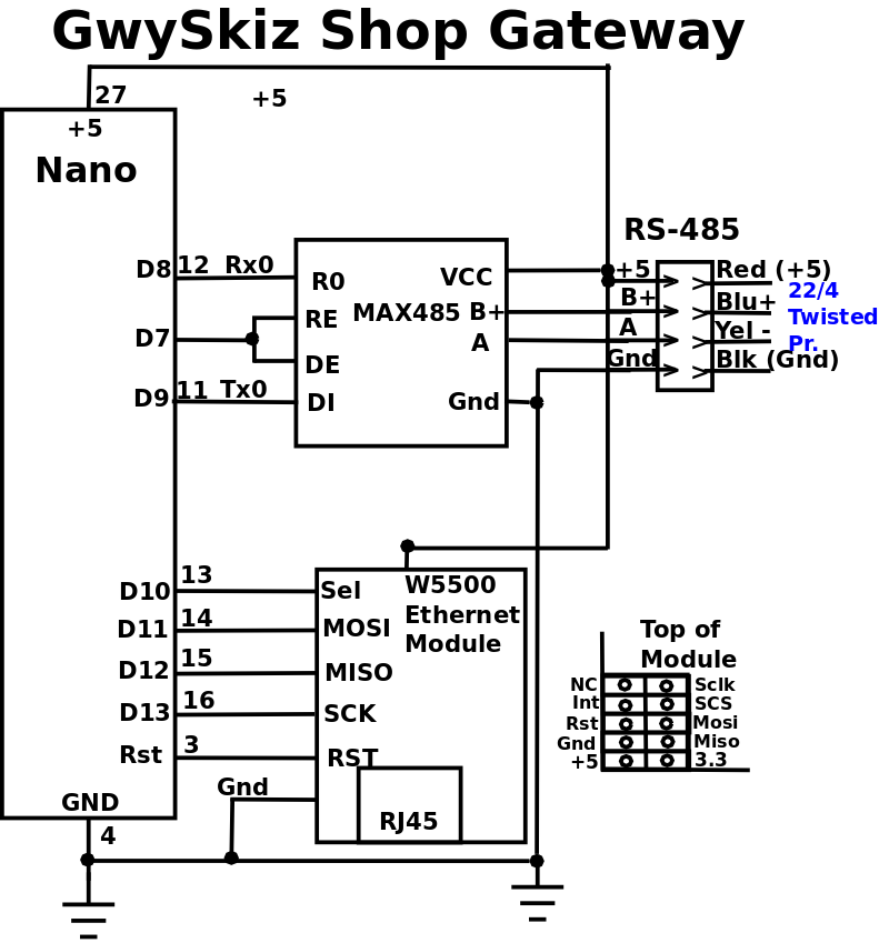
GateWay:
A gateway between the in-house ethernet network and a new RS-485 network in the shop.
The gwy will run on a Nano with an Ethernet Module, use AltSoftSerial, and a RS-485 adapter interface as the master of a RS-485 network in the shop.
TCP packets will only contain ascii characters, including an 8 char Info header, containing a 4 char packet length field and 4 extra bytes followed by an abbreviated slave name ("EN" environment, "AC" for mini-split thermometer, "DA" dust automation.
The gwy will use RS-485 for communicating with the devices (slaves) in the shop: Env, DustAuto, Shop AC thermostat (mini split AC), and Sprinkler System.
The RS-485 devices will be using ascii characters with a crunch (#) followed by a 2 digit slave number and any arguments required by the slave.
RS-485 messages will contain a small, initial vector address which will enable gwy to determine the message's destination.
When a request arrives it will be forwarded to the correct server, wait for the response, and forward the response back to the sender on the ethernet network.
In this 1st version, during the processing of the request no other requests will be accepted, since most of these request take minimal time (ENV query takes < 3ms).
Requests and responses should be very quick, only tying up the gwy for a few MS.
NOTE:
Arduino has come out with a Nano Ethernet Shield and a Nano 485 Shield.
Now if you can stack the W5500 based Eth Shield, 485 Shield, and a Nano, that would solve the mounting/PCB problem, and should work great!
Only promlem is $$$$$, $26.40 for the Eth Shield, and $45.49 for the 485 Shield.
I'll just have to wait for them to come down in price.
+5 Volt Power
The Env server's power will be supplied from the ShopGwy.
Since the ShopGwy is never powered off, and I want the Env server available at all times for our web servers, the Env server will draw +5 volts current from the ShopGwy.
When Testing allow the V8 RS-485 cable to the Env server to supply 5 volts (red wire connected).
When installing, be very careful about not connecting the +5 volt power between V8 controller and Env Server (just don't connect the red wire in that cable).
Under installed conditions, power (+5 volts) is supplied from Gateway to Env server, when testing, v8 supplies power to Env.
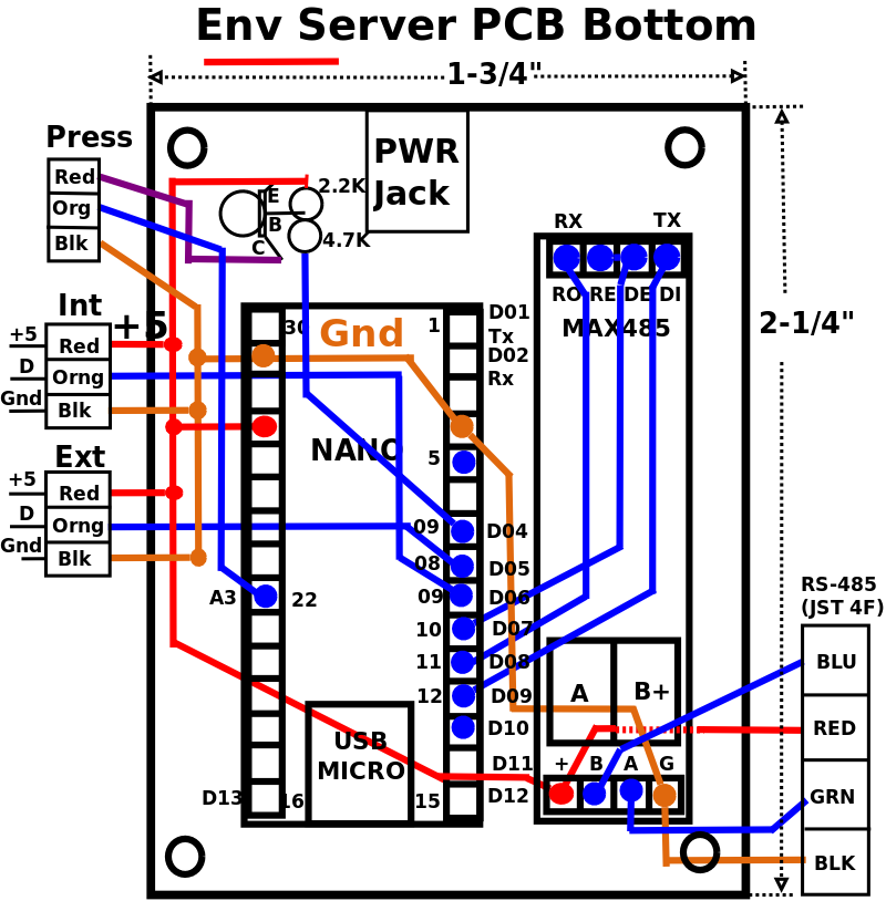
It is difficult to get more than two wires in a screw terminal (like the Nano Breakout's).
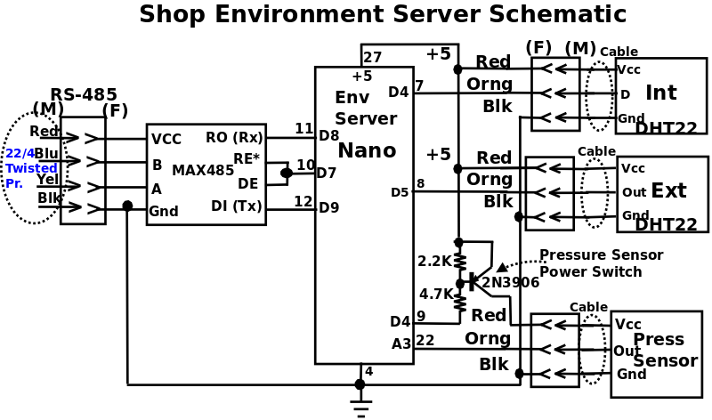
I came up with this power distribution device to handle the four ground and four +5 volt power wires for the connectors to the two DHT22s and 4 wire JST connectors for the rpi and V8 controller.
Env
(Env Server), will be running on an Arduino Nano, mounted on a Screw Terminal Adapter Shield Expansion Board and will use Software Serial for the link to/from V8 and Hardware Serial for the ShopGwy's requests.
Env will measure temperature and humidity using DHT22 sensors.
I chose the DHT22s because they are more accurate than the DHT11.
The DHT22 sensor outside (Ext) will need to be in a weather proof housing, made from 3/4" PVC, that allows free air circulation with the outside air.
I need to test long cable length comms to the DHT22.
The Nano Env Server will be mounted in a Nano Breakout Box, similar to the Dust Detector.
Hardware:
Diagrams
Testing
|
NanoEth ENC28J60 and Env test.
|
|
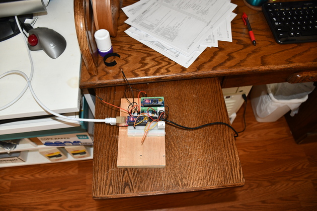
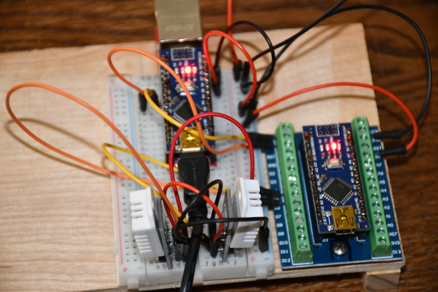
Closer look at the test lash-up.
At the top is the EnvSvr Nano, mounted on a Nano breakout board.
Below is a breadboard with the Nano and an ESC28J60 (Ethernet shield), also two DH22 temp/hum sensors.
|
|
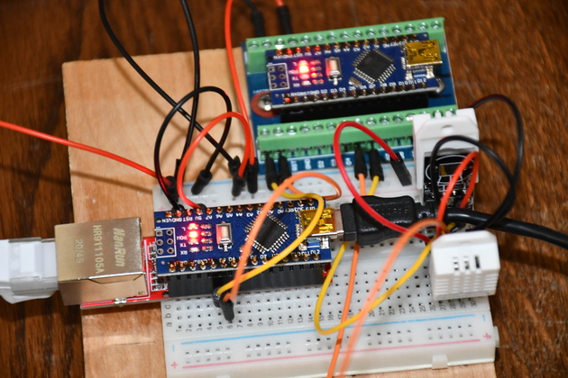
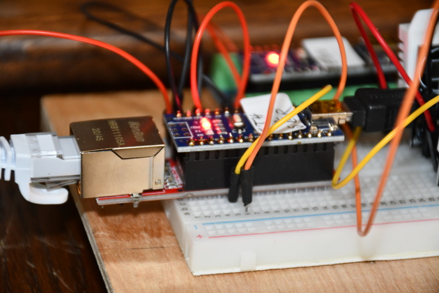
Different angle.
On the lower left you can see the two DHT-22s plugged into the breadboard.
Note: the NanoEth Nano (left) plugged into my workstation, and the Env Nano getting it's power from NanoEth.
|
|
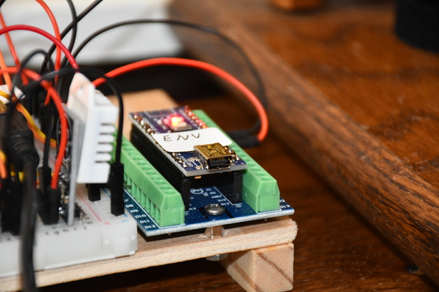
Better view of the ENC28J60 with it's Nano on top.
|
|
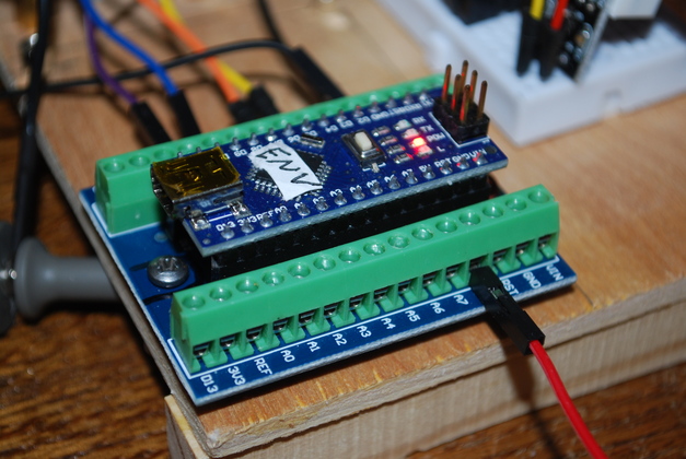
The Nano running Env.ino plugged into one of the Nano screw terminal breakout boards.
|
|
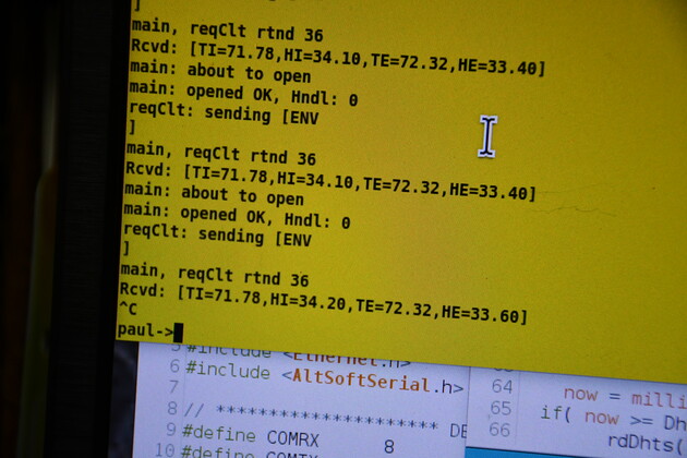
The output of nanoTst.
The "sending [ENV" command sent to the Env server.
The bracketed characters [TI=71.78,HI=34.20,TE=72.32,HE=33.60] are from the Env Servr via the nano gateway.
Both sensors are close together so the numbers are also close.
|
Env Info
|
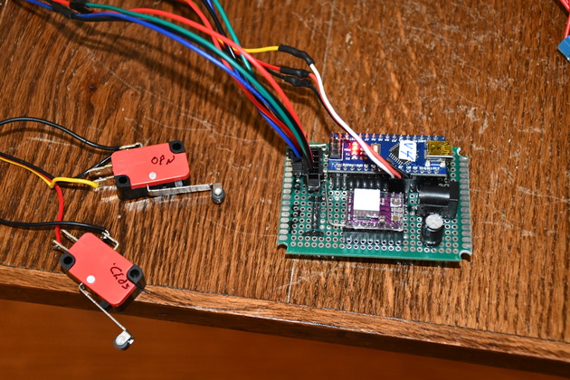
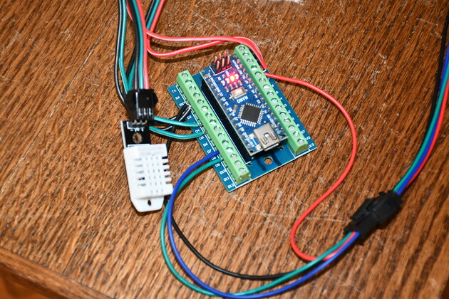
Original Nano Env Server with of it's DHT22 sensors.
|
|
The Nano plugged into one of the screw terminal breakout boards mounted on my test board.
Note: the Env Nano is getting it's power from the NanoEth Nano..
Since I have a number of Nanos, I put a sticker on each stating the program loaded into it.
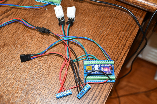
Interesting power distribution device.
|
|
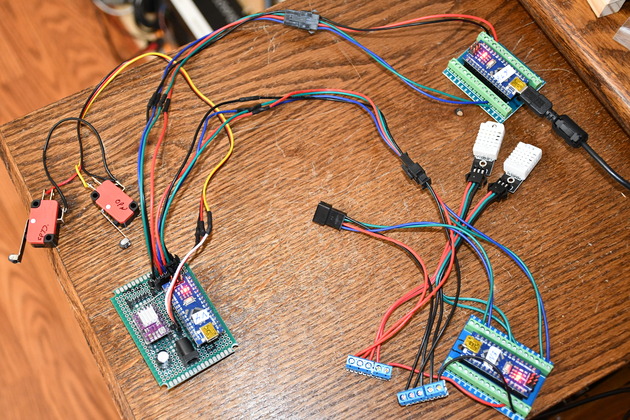
Testing softwareserial in 2 servers.
Using a simple relay Nano (in port A out port B), I'm testing communication to Env server via Valve8 controller.
Rly Nano is top right, Env server is bottom right, and V4 is left.
You can see the V4 limit switches on the left.
Note USB cable into Rly, both the other servers are powered from Rly (USB)
|
|
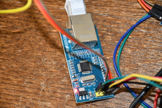
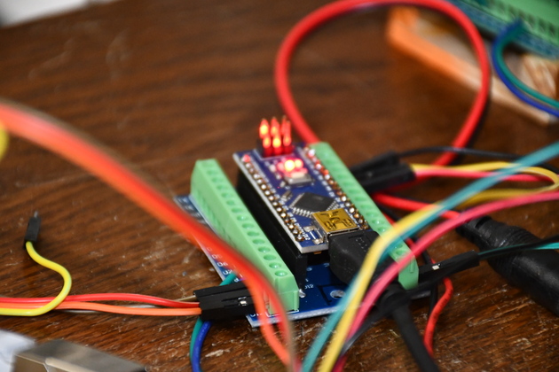
Closer look at the W5500 Ethernet Module.
Note, the connector pins stick up, instead of down where you can plug them into a socket on a board.
|
|
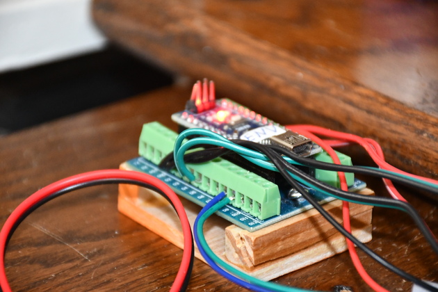
Closer look at the Gateway.
|
|
Closer look at the Env server nano.
|
Install
|
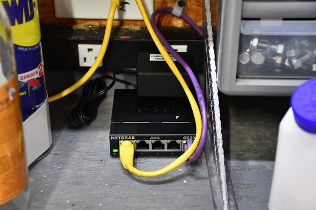
This 5 port gigabit switch, on the south wall of the small shop bay, is connected to our 1Gb backbone (yellow CAT-5).
|
|
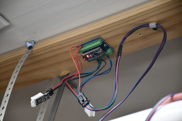
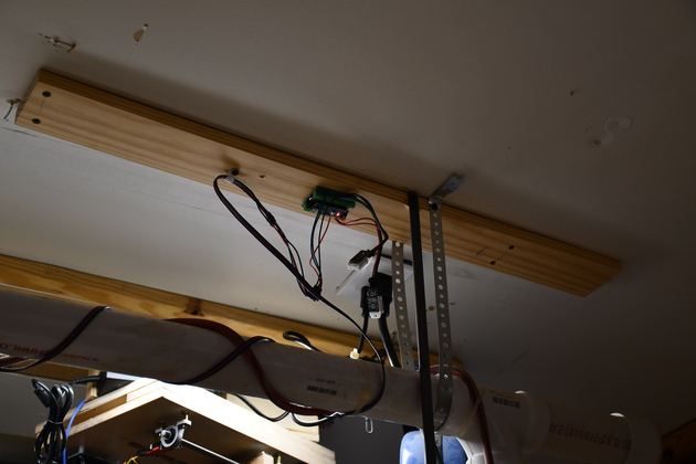
The Env server (environment server) installed above the work bench.
I still have to mount the internal and external sensors.
The external sensor will be through the garage ceiling in the attic.
I always wanted to be able to ched the attic tremp, now I can.
|
|
From a different angle, note the V8 slide valve at the bottom of pic.
When I connect the Env server to the DustAutomation (DA) system, it'll be via the V8 controller which is nearby.
|
|
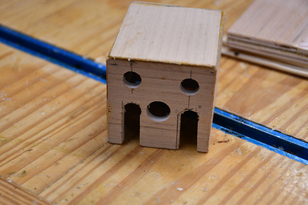
Housing for Env server.
Please see Nano Mount for more details.
|
|
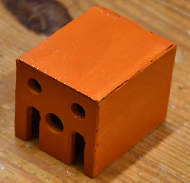
After painting a distinctive color.
|
|
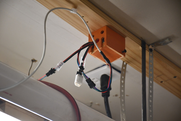
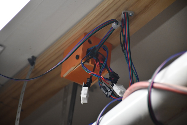
The Env server mounted in it's orange box, on the shop ceiling.
You can see the white RS485 wire and the Internal sensor.
The wire, just left of the sensor, goes to the attic sensor (Ext).
|
|
Another angle.
Note how the cables fit into the mouseholes, its easy to remove the Nano from the box without unplugging any cables.
By the same token, its easy to plug in the cables before putting the Nano into it's box.
|
|
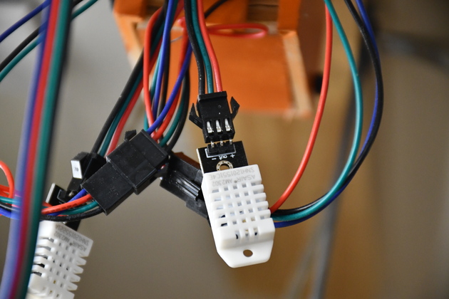
Sensor connection before the Ext sensor was moved to the attic.
|