Initial 5 Port Plenum |
| ||||||
|
Dc6 Revamp
| |||||||
|
Initial 5 Port Plenum |
| ||||||
|
Dc6 Revamp
| |||||||
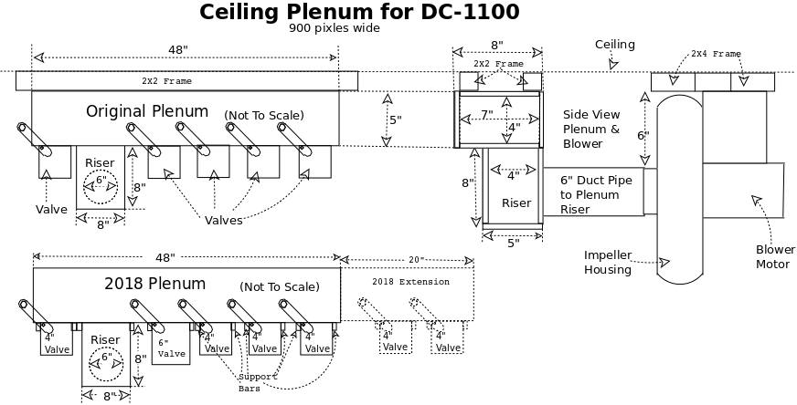
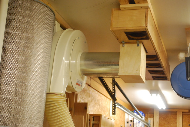
The Dc6's main plenum has the same cross sectional area as a round 6" pipe (approximately two x 4" pipe area) allowing me to have two 4" valves or one 6" valve open at the same time.
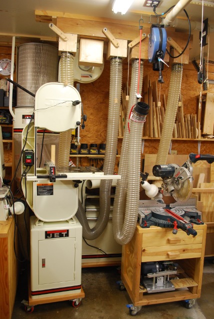
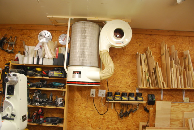
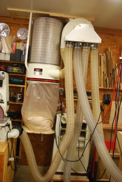
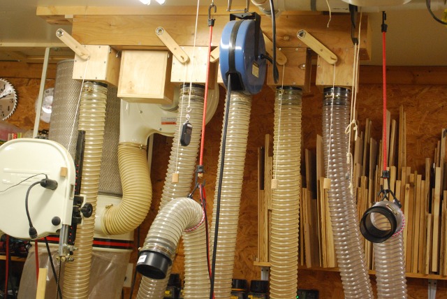
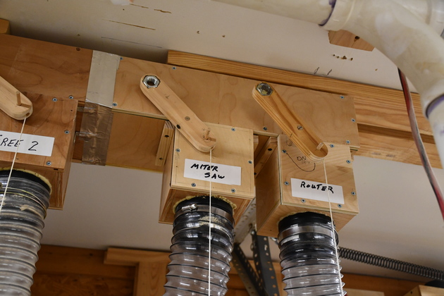
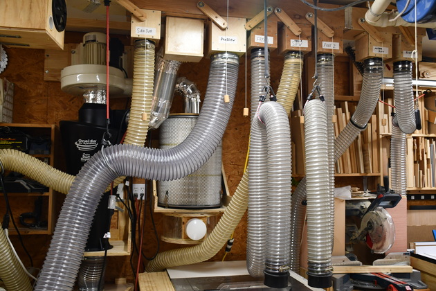
I moved the Dc6 system to the ceiling, off the floor, with a longer plenum, more taps, and replaced the old metal blast gates with updraft valves. Moving the system up off the floor, makes the chip bag more visible (so I don't overfill it) and makes it easier to empty the bag. Moving the plenum and valves to a central place, on the ceiling, made it very easy to see which valves are open and closed, also to open and close the valves via their "toggle strings".
Organ Wind Chests
Before I built these I got to thinking about the way pipe organ wind chests are made (with internal valves) and decided I could make a wooden plenum (larger than the old 4 port I made earlier) that had a valve for each 4" port.
The differnece between a vacuum plenum and an organ wind chest is, of course, negative pressure and the high wind velocity within the plenum.
Organ valves don't have to open very far just to allow enough air to flow past to sound the pipe and they must open and close under pressure.
Dust valves must open wide to allow high wind volume laden with chips and you can have the pressure off when opening or closing.
If the wind velocity drops the chips fall out.
In the old system I had a blast gate at the end of each hose, usually behind each machine, which is hard to operate, and in most cases, difficult to tell which is on or off without looking (or feeling) behind each machine.
I decided I wanted the valves at the new plenum, up near the ceiling, and easy to operate and see their status at a glance.
New Plan:
I'll have to seperate the motor/impeller from the chip handling (Cyclone, filter, and chip bag) rotate the motor/impeller upside down and mounting it on the ceiling and raise the chip handling up higher.
There will be a 4 ft. long rectangular plywood plenum, mounted on the ceiling, with 5 home-built, modular, valves for five 4" hoses, and a riser to couple to the DC motor/impeller.
The 4" hoses will hang down from the valves without bungies.
Plenum:
The plenum will be made from 1/2" birch plywood, painted with polyurethane to reduce friction and turbulence.
The fronts of the plenum and valve boxes are removable, for cleaning, with a felt gasket and be held on with #8 flat head screws.
There are felt gaskets between the valve box and plenum, and on valve box and plenum fronts so the fronts may be removed for cleaning.
Valves:
Lots of folks call these "Blast Gates" but to me there Valves.
There are two kinds of slider type blast gates, a knife which closes into an enclosed space and the second slider which has a round opening that moves in and out of alignment with the air flow.
The first kind (knife) frequently catches small amounts of dust and packs it into the enclosed are, over time causing the gate not to close completely.
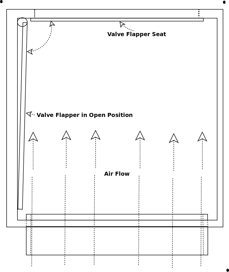
Valve Design Goal: air flow tends to keep the valve open and vacuum holds the valve shut.
The valve boxes will be made from 1/2" birch plywood, the valve flapper will be 3/16" birch plywood.
All parts, inside and out, are painted with polyurethane.
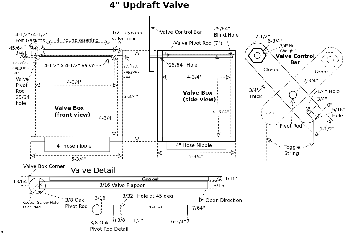
One edge of the flapper will be glued into a notch machined into a 3/8" round hardwood dowel pivot rod.
One end of the flapper pivot rod will rotate in a 25/64" blind hole in the rear of the valve box.
The other end of the pivot rod will proturde through the front of the valve box through a 25/64" hole far enough to allow a control bar to he attached.
The control bar will have a large steel nut and bolt as a top wieght and be at a 45° angle with the flapper.
The weight in the top of the control bar, because it is at a 45° angle, will hold a slight pressure against the flapper so that it stays either open or closed.
The valve box will have a sticky-back felt gasket where the flapper closes to the top of the valve box.
When the flapper is open (almost vertical) the control arm's weight, will push it (horizontally) against the inside of the box, out of the way of the air and chip flow so there will be minimal pressure on the flapper.
For more info on how the valve works please see my Updraft Vavle page
The fronts of the valve boxes will have a felt gasket and be removable, for cleaning, and be held on with #8 flat head screws
.
The valve will have a 3/8" oak pivot rod with a 1" x 2" valve control bar on the outer end, attached with a pin.
The valve flapper will be glued into a slot routed into the pivot bar.
The valve control bar will sit at 45°, top left when closed and 45° top right when open.
The valve control bar will have a weight (3/4" nut = 1.8oz.), imbedded into the upper end, 4" from the pivot point.
The weight will keep the valve in either the open or closed position (gravity CAN be your friend).
The toggle action of the valve control arms also acts a a kind of memory so when the vacuum is off the valves stay wherever they were placed.
A quick tug on the toggle string (2" from pivot point) will toggle the vale open or closed (opposite position)
The valves are modular, that is, each can be removed and dissasembled, for repair or replacement, I could even block one off if it was necessary.
For more about the valves please see my updraft valve page.
Wind Velocities
Wind velocity is key in dust collector plenums and valves (particles drop out if the velocity slows).
I need to keep the interior fairly clean (no bumps, sharp edges, or rough surfaces) to reduce friction and turbulence.
The motor/impeller has a 6" round input (28.27 in²) duct, so the plenum will have a 4" by 7" interior dimension (28 in²).
The valve will be 4-1/2" square and have a 4" (12.56 in²) round opening.
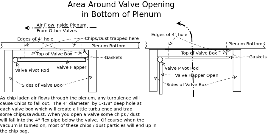
The valve box will be 4-3/4" square (21.36 in;² when open) (4" hose has 12.56 in²) so wind velociy will drop slightly inside the valve, but this is vertically oriented, meaning no sawdust buildup.
Here is a link to a quick diagram explaining where chips / dust will be trapped.
I need to keep the cross sectional areas (CA) about equal so wind velocities will be fairly constant.
That said, the main plenum and riser is the same CA as a 6" round duct, the valve boxes are near the CA of a 4" hose, so I can have multiple valves open at once.
The interior and exterior surfaces of all valves, the plenum, and riser will be painted with clear polyeurethane so dust will flow easier.
Plenum Wind Velocity NOTE: I wasn't explicit above, the DC-1100 is capable of running two 4" ducts at the same time, so the plenum is twice the cross sectional area of a single 4" duct. This means that under normal conditions, one 4" valve open, the velocity drops to about half of the full velocity. We know there will be some chips dropping in the plenum but the half wind velocity is still enough to keep the plenum clean except for the valve openings themselves.
One other change I made is to add a remote for the DC's power hanging from a string about center of the area where I use the machines. Previously, I had to walk to the opposite side of the room and reach around the corner to operate the power switch for the DC, I know it's not that far, but when you do it a whole lot... Moving the switch made a huge difference in convenience and time saving when switching from machine to machine.
After using it:
This thing is great, easy to use, convenient and I think I have more suction (no reasonable explanation?).
Before, when I started the DC up, the hoses would all contract since the blast gates were at the machine end of each hose (meaning all the 4" hoses were under vacuum), now, nothing moves except the one(s) turned on.
I didn't think adding the pendant to turn the DC on and off would make the difference it does, the fob is in reach on almost all the machines.
Having all the valves in sight from everywhere in the room is a huge improvement, I don't have to go around looking or feeling behind each machine to see whats open and whats closed.
All in all it makes changing from one machine to another very simple and quick.
12/01/16:
Now I have used the ceiling valves for over a year and I love it.
I have had to access one valve, I sucked up a long splinter (about 4-1/2" long) which jammed a valve in the almost open position.
I took the hose off the bottom, reached up into the valve housing and pulled the splinter out, voilla, it works great again.
2018
I replaced the #2 4" valve with a 6" valve for a new Jet JWBS-14SFX BandSaw which required two 4" dust ports.
I like to dedicate a hose (and valve) to each frequently used machine, it reduces the things I have to do when I move from one machine to another.
The new 6" valve will have a 6" hose to a 6" to dual 4" 'Y' and two 4" hoses to the two ports on the bandsaw.
I also added a 20" extension to the North end of the 4" plenum with two more 4" valves, for the miter saw and the new roll-around router table.
Since I originally designed the ceiling plenum to allow two 4" ports to be open at once, a 6" valve should work fine.
2020
During the COVID-19 pandemic, I decided to Automate the larger DustCollection System.
| |
| (Click on Diagrams for larger pics) | |
|
|
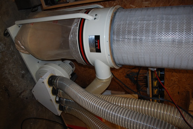
| The 4" Dust Collector system: filter, separator, and chip bag in it's original position on the floor. On the right is the motor/impeller, 4 port plenum, and upward hoses (downward hoses not shown). |
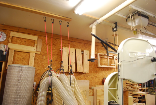
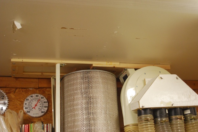
| The ceiling where I want everything to end up. The 2" drop down will be moved to the right, past the right hand 2" blast gate (other side of Genie). The 1x4 holding up the hoses and electric cords will be gone. Note the space taken up by just the hoses. |
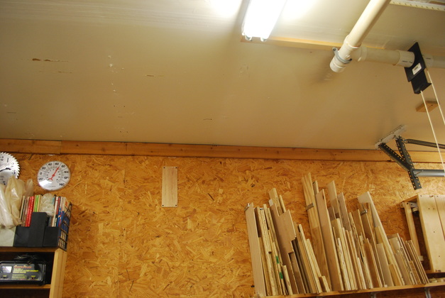
| The ceiling after I removed the old 4" hangers, this is where the DC and hoses will end up. I also moved the 2" drop over. This is before I replaced the 2" blast gates with slider valves and plenum. |
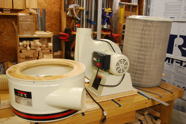
| Primary parts of the Jet DC-1100 taken apart on the workbench. You can see the wooden donut in the separator top (on the left) used to hold the Wynn Filter, and the Wynn C1425 Filter itself on the right end of the bench. BTW I am still ecstatic over the Wynn Environmantal C1425 filter, Here is a Link to the Wynn Filter Installation Page and Wynn Environmental's Site. |
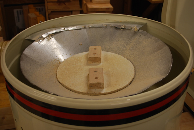
| The separator upside down, you can see the bottom of the cone I built and the tinman's hat on the far side. This thing is clunky looking but it works great. Link to Jet DC-1100 Seperator Improvement Page. |
| Closer look at the base. The 2x4 part holds the motor/impeller (and spans two ceiling joists), the 1x4 part is for the chip handling part (separator, filter, and chip bag). BTW the chip bag will mostly be supported by a shelf, built under it. |
|
The base with motor/impeller, separator and filter mounted on the ceiling.
Notice, I rotated the 3 separator support legs, vertically, 180° (upside down) just like I did the motor/impeller.
Turns out the length was correct so the Wynn filter would easily fit.
|
| The motor/impeller should be moved to the right so the 5" hose from the motor/impeller to the separator has a little smoother curve (not an 'S' curve), but I wanted the anchor bolts to go into a joist. My only concern about this is the sharper turn will cost some wind velocity going into the separator. Another thought, move the motor/impeller to the right and replace the flex hose with 5" metal pipe and a 5" ell. Also moving the motor/impeller to the right will give me a little more clearance if I replace the filter with a larger diamter. As long as Wynn Environmental is in business, I should be set with this size. |
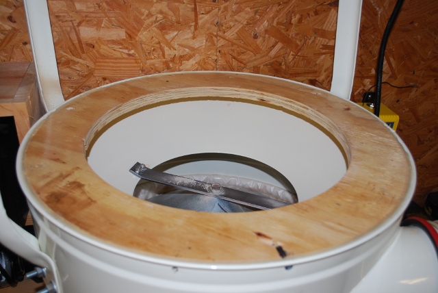
| Here is the system using the old 4 port plenum. You can see the little plywood shelf I made to hold the chip bag. Raising the chip collecion bag makes it a little easier to change. |
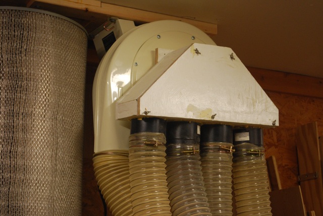
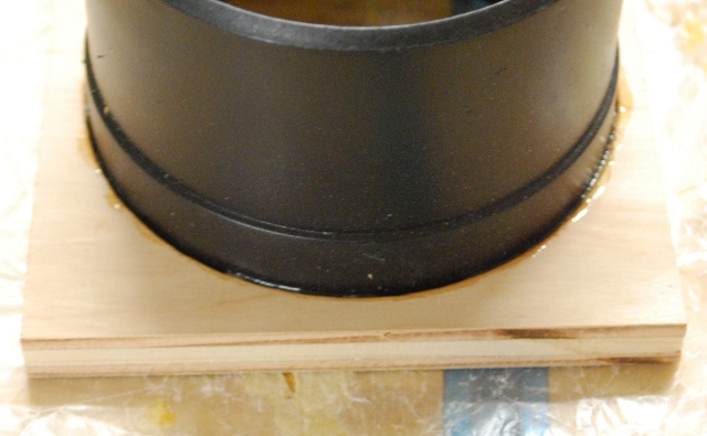
| The old 4 port plenum is held on by the vacuum. |
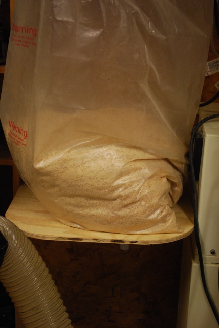
| I cut out a 1/2" plywood shelf to hold the chip bag. |
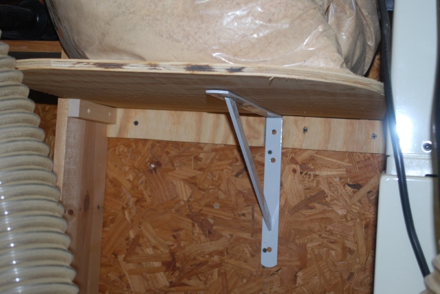
| Braces under the chip chip bag shelf. |
| This is where the new plenum and valves will go, replacing the current 4 port plenum. |
|
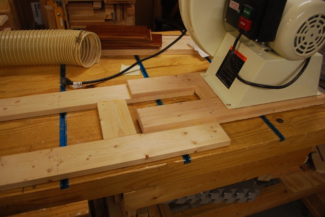
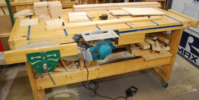
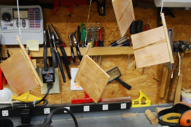
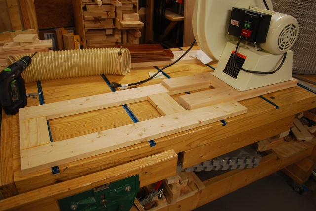
I needed to cut up a lot of plywood, with really straight, clean edges, something which I'm not really set up to do a lot of.
So I came up with the Plywood Ripper.
Using this thing is like using a table saw.
|
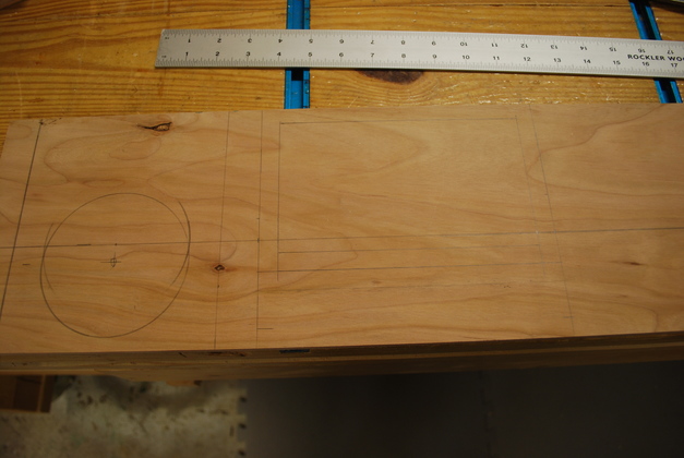
| Marking new plenum bottom piece for holes to valves and motor/impeller riser. I cut all the round holes using a hole saw on the drillpress. |
|
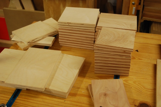
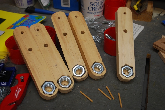
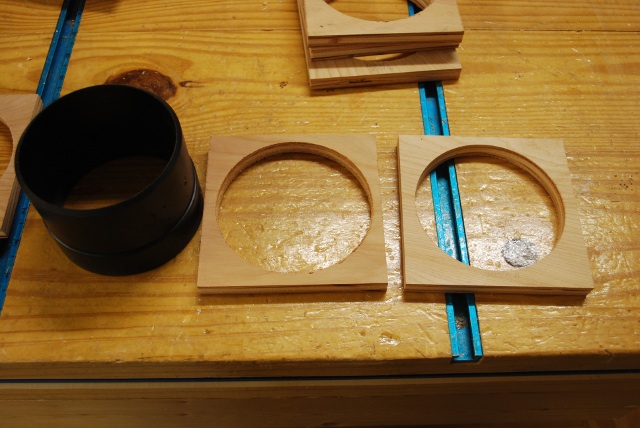
Stacks of valve parts sawed on the Plywood Ripper or table saw.
Note the nice straight edges, good for gluing air tight joints.
|
|
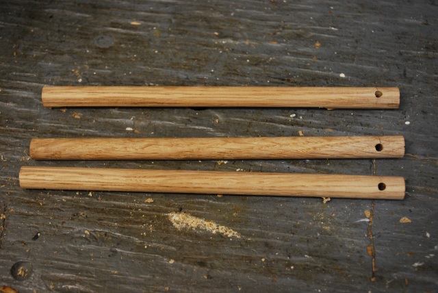
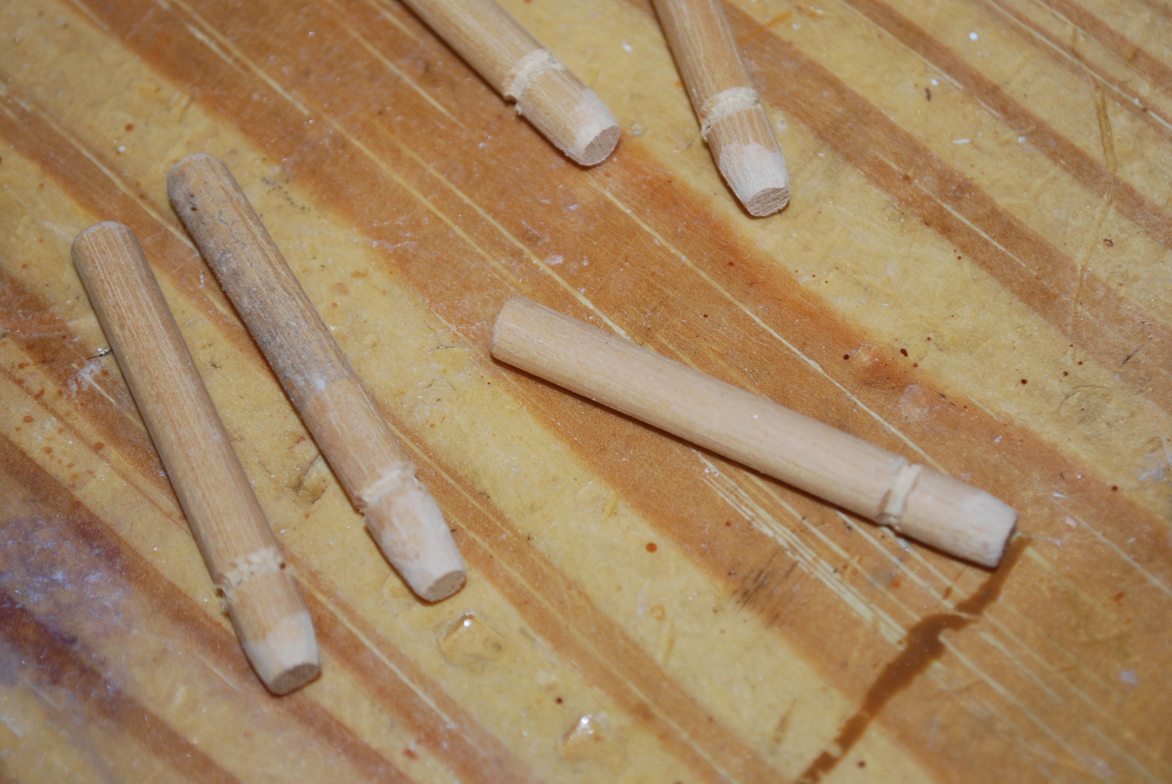
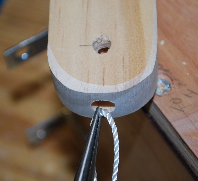
3/8" valve pivot rods with a 1/8" keeper screw hole drilled in one end.
The keeper hole will be used twice, the first time with a short peg to hold the rod's orientation while routing a slot for the flapper, then in the final assembly, with a wallscrew (keeper), to hold the valve control bar in place.
The center line of this hole must be 45° from the slot in the bar.
|
| Two pieces of 3/8" plywood to hold the bar while routing. |
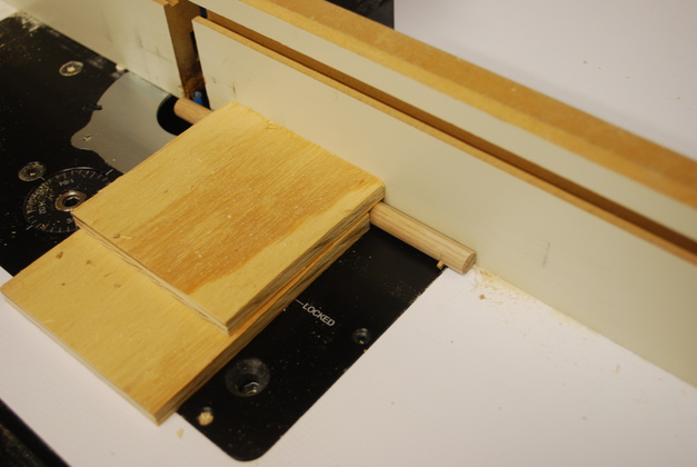
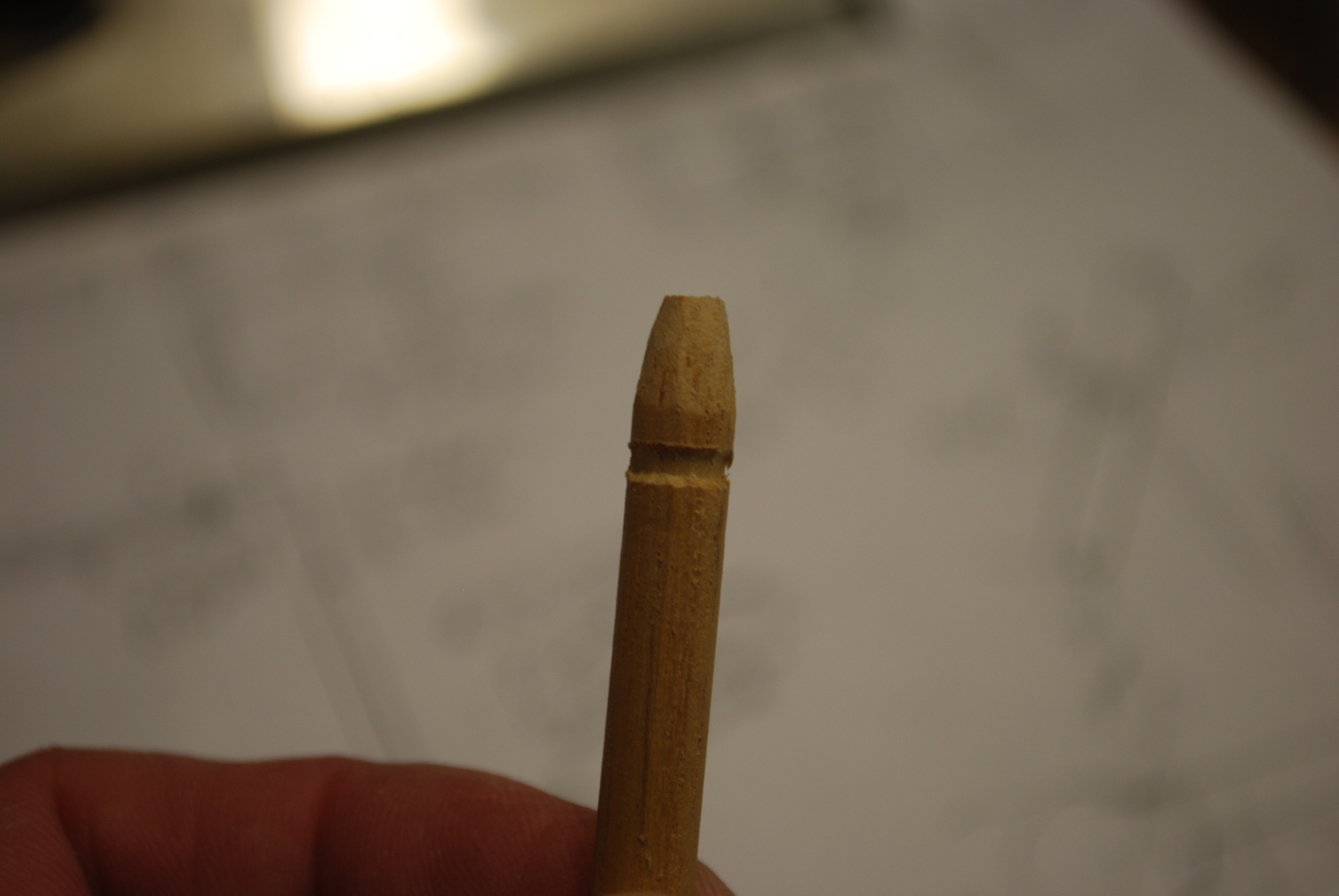
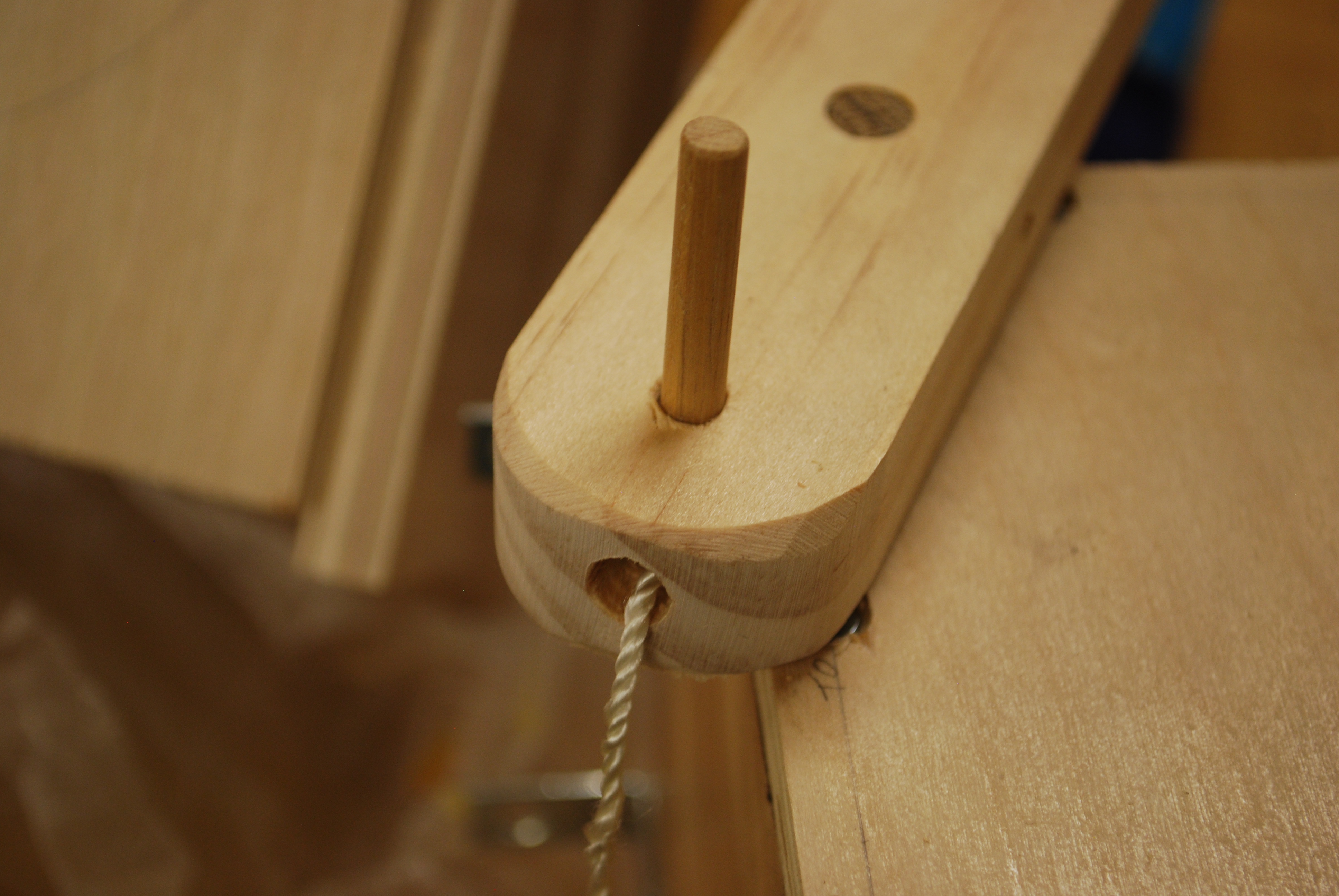
| Close up of the short peg, I keep it against the router lift and fence, while routing, in order to route a straight slot for the flapper and to keep the 45° angle of the hole. |
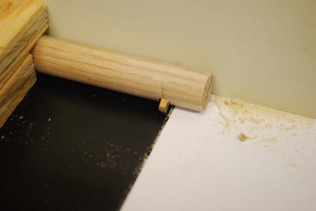
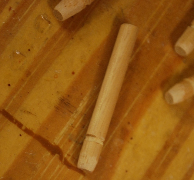
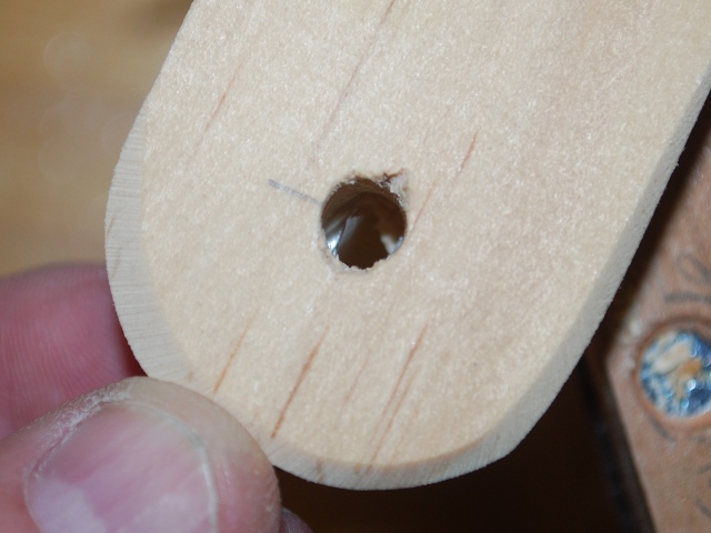
| The slot starts about 1-1/2" from this end and goes to 1/4" from the opposite end. You can see the line, on the far end of the pivot rod, which is the center line of the flapper. |
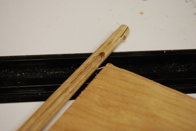
| Flapper being glued into the slot on the pivot rod, you can see the peg hole is about 45° from the flapper. |
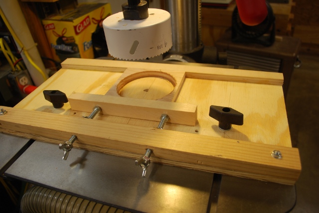
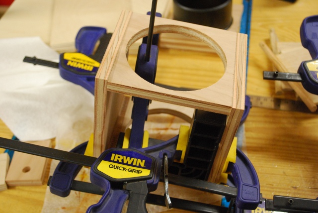
| Hole sawing 4" holes in valve top. When you use a large hole saw you have to clamp the piece very securely. |
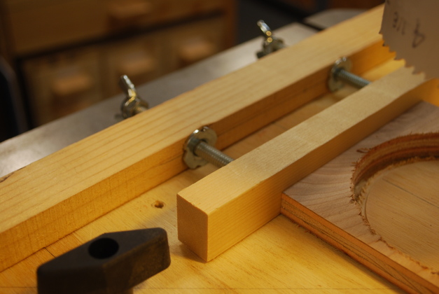
| Note the tee nuts and push bar. |
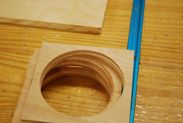
| Stack of valve tops with 4" holes sawed. Hole saws leave rough holes so this took some sanding to get them looking like this. |
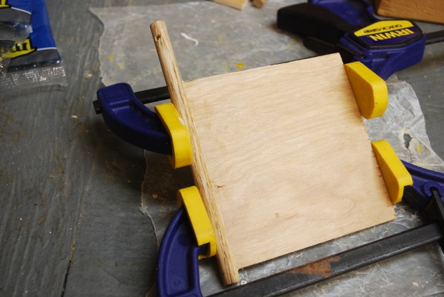
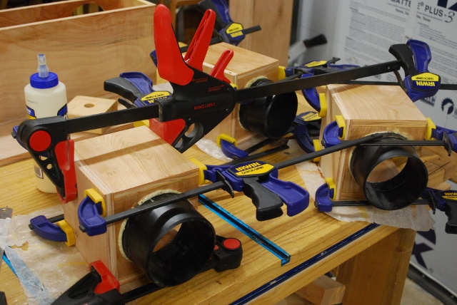
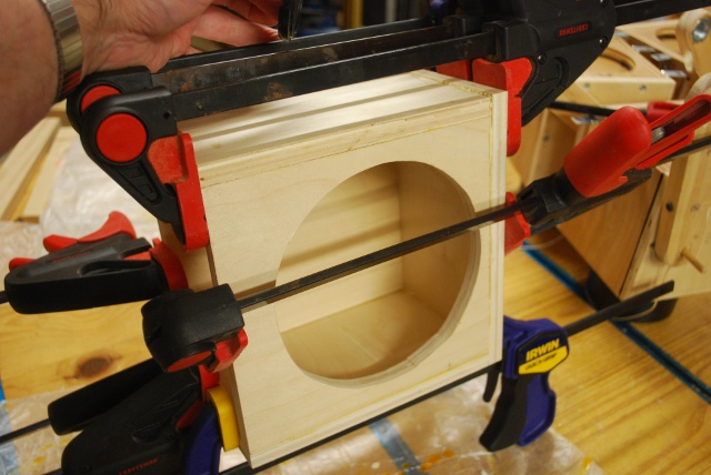
| Valve box being glued up, top and sides, the bottom (on top in pic) is just there as a spacer now. You can see a mini ClampIt to keep things square. |
| The Gorilla Glue is starting to foam. |
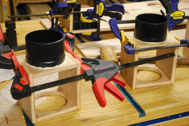
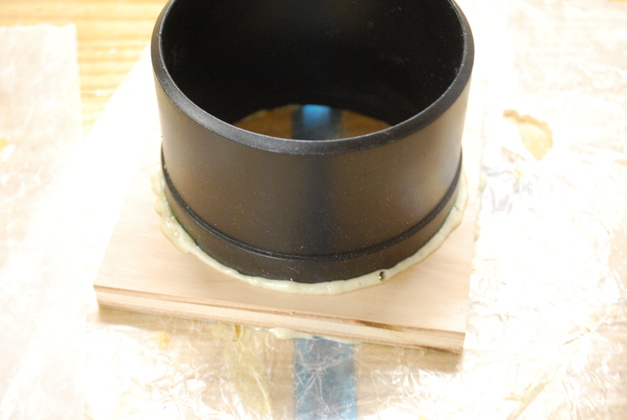
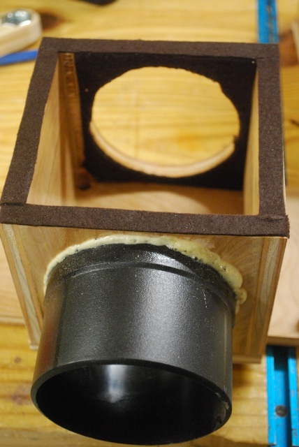
| Bottom being glued into valve box after the 4" nipple is Gorilla Glued, you can see the foam at the base of the nipples. |
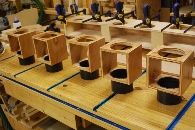
| Valve boxes being painted. You'll note the top of the nipple is flush with the inside of the bottom so the valve will clear and there is minimum turbulence. |
| Flappers being painted. |
| Backs being glued on valve boxes. |
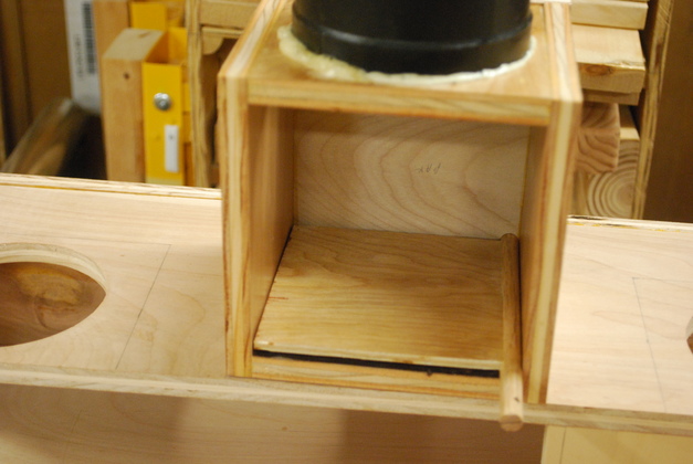
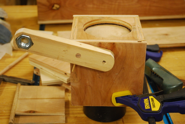
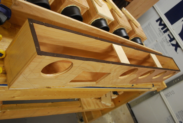
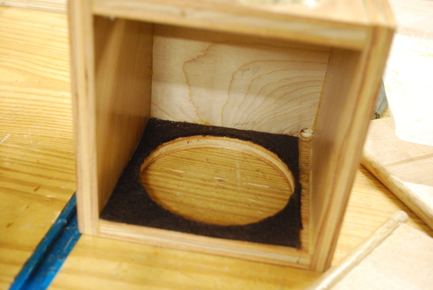
| Valve box on top of plenum with valve flapper closed. A slot is machined 1/32" for the pivot bar so the flapper will lie flat on the 1/16" gasket. The distance from the surface of the flapper to the top of the pivot bar is 3/32", see valve detail at the bottom of diagram, the gasket is 1/16" so the slot is 1/32" deep. |
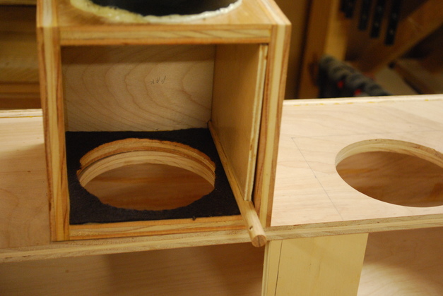
| Valve box on top of plenum with flapper open. The valve box is built to pretty tight tolerances since I don't want the cross sectional area to be much larger than the 4" hose feeding it. You can see here the open valve flapper reduces the CA (Cross Sectional Area) to about 21.56in². The wind flowing, top to bottom in the pic, will help hold the valve open. |
| Valve control bars, here I'm letting the drop of glue holding the nut set. You can see the imbedded nut, the 3/8" pivot bar hole, and the toggle string hole at the top. The pivot hole is 4" from the center of the weight and 2" from the pivot string hole. For the weights (Nuts) I bored a blind hole the diameter of the flats on the nut, then "notched" out for each of the six points, so the nut is "press fit" into the control bar, thats why it doesn't take much glue to hold them. |
| Valve control bar in closed position. I got the angle a little off the keeper hole in the pivot rod, I'll redrill it to 45°. |

| Valve control bar in open position. The nut weights 1.8 oz. the flapper weighs 1.4oz., the vacuum will help hold the flapper closed, and wind will help hold it open, along with the weight of the nut, but it should be about 45°. The control bar is always at a 45° angle to the flapper (45° open and 315&qdeg;closed). The valve flapper and control bar (static body) rotate 90° from open to closed. The 45° angle means there will be about 1.59oz. of horizontal pressure on the flapper holding it open and closed (the vacuum also helps hold it closed). |
|
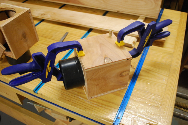
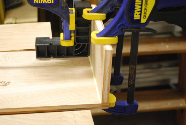
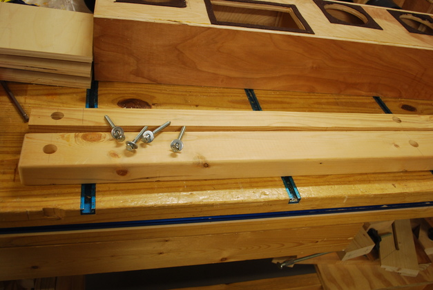
Front clamped ready to drill the screw holes.
I used 1" flat head #8 hex screws (countersunk) to hold the front of the valve box on and the front of the plenum.
|
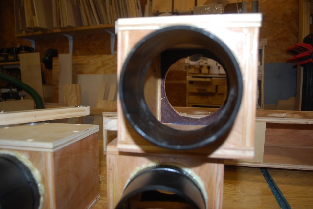
| Looking up through the open valve, you can see the flapper on the left side, well clear of the wind and dust chips. The wind flow, pushing slightly against the top (now horizontal) will also help hold the valve open. |
| A look at the felt gasket under the front cover. This is 1/16" thick sticky back felt, I got it at Hobby Lobby, all the gaskets are made from the same stuff. |
|
|
|
|
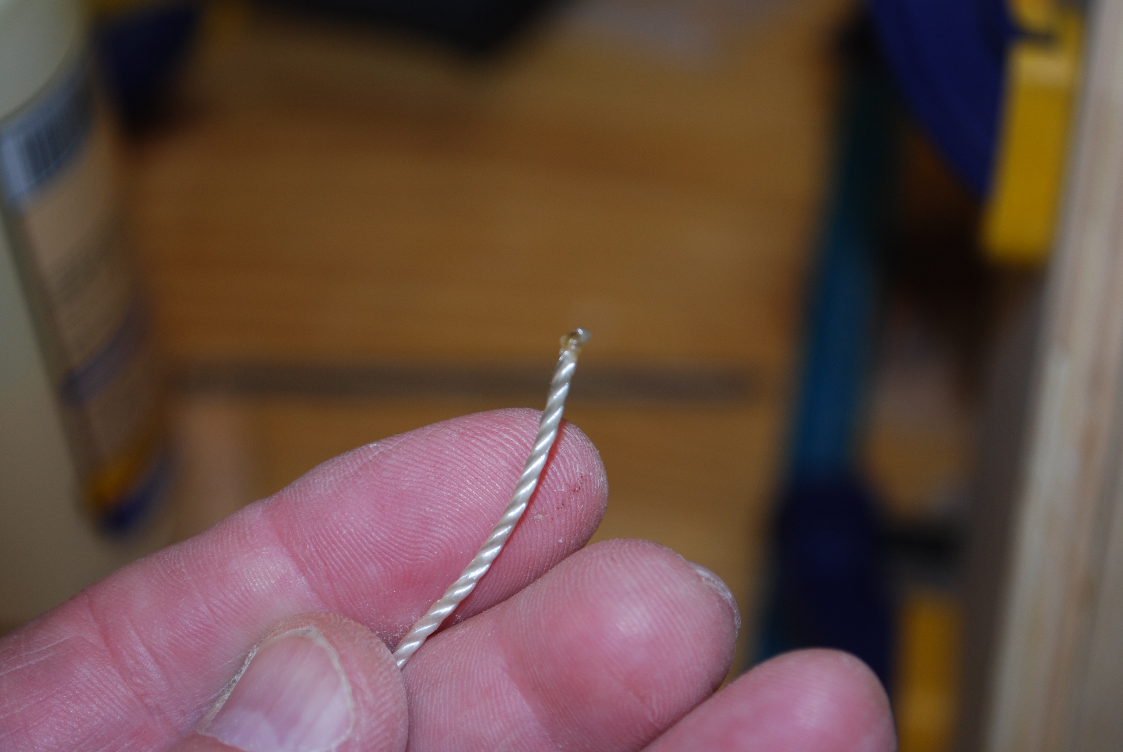
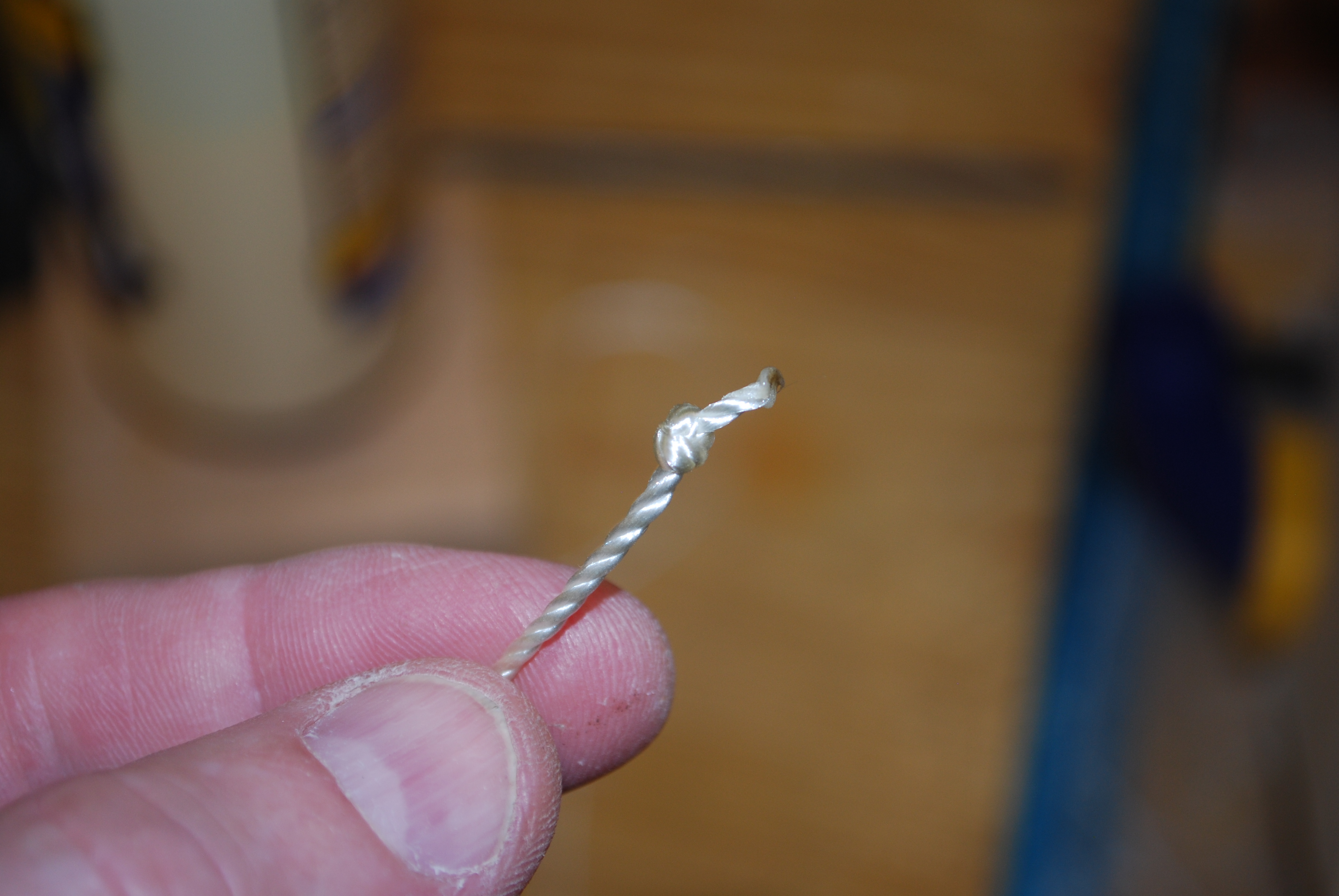
This peg will be used to hold the toggle string. 1/4" dowel with notch, 3/8" from end, chamfered with a pencil sharpener. The chamfer helps penetrate the string's loop inside the control bar. | ||
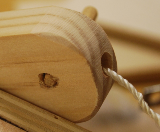
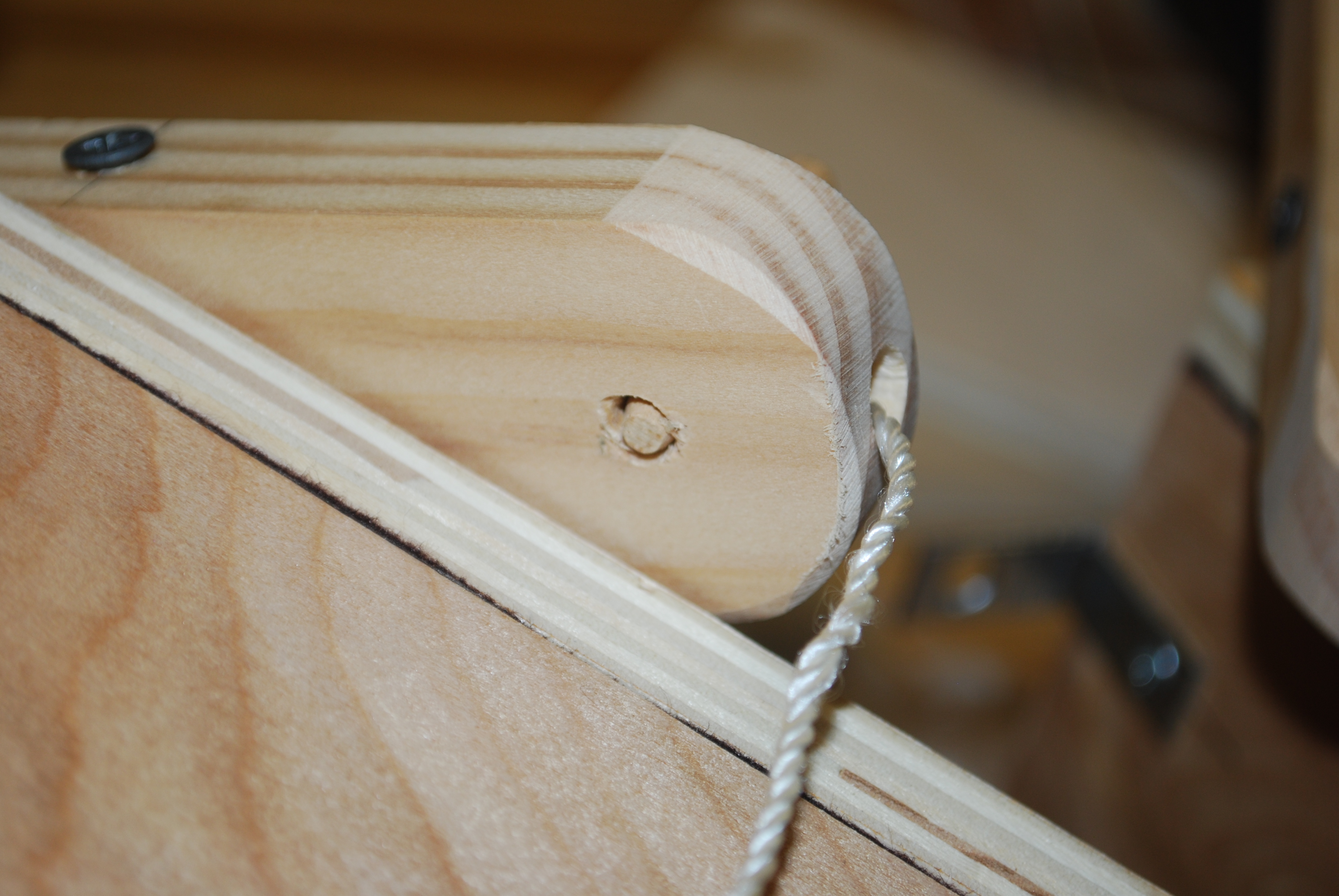
| Back side of control bar with peg holding the toggle string. You can see the 1/4" bore for the pin and the 5/16" bore for the string. |
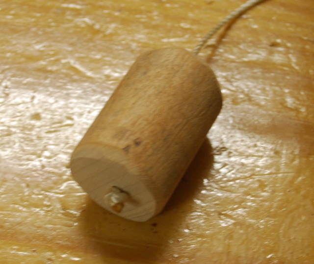
| Cut a 3/4" dowel into 2" segements, drill a center hole, just big enough for the toggle string. Feed the toggle string through the hole and double knot it. This makes a gem dandy handle for the toggle string. |
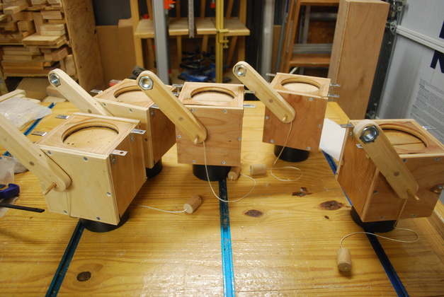
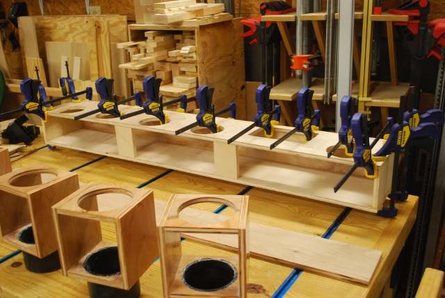
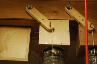
| All 5 valves, with toggle strings, ready to install. Note their mounting brackets on the top. |
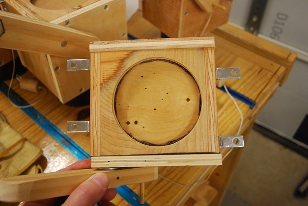
| You are looking at the top of the valve box. The mounting brackets are staggered so I can mount the valve boxes closer. The gasket for this surface will be stuck to the plenum box. |
| Plenum ends being glued. |
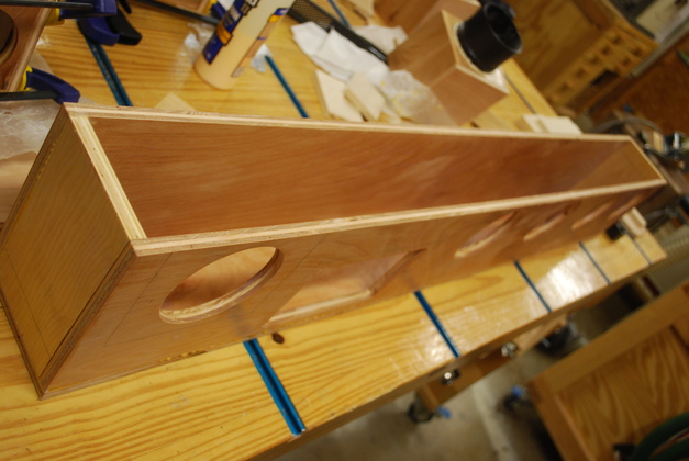
| Bottom being glued. In this pic the bottom is reversed, end to end. Inside the plenum, the wind will flow from the one or two round holes to the rectangular holes. The two spacers will be glued in later, right now they are for spacing only. You can see the 5 valve holes (4" ea.) and the riser hole (7" by 4"). |
| Inside of plenum being painted. |
| Two front supports being glued in, the back side of each is beveled 45°, and painted to cut down turbulence. |
| Gasket on front edge of plenum. |
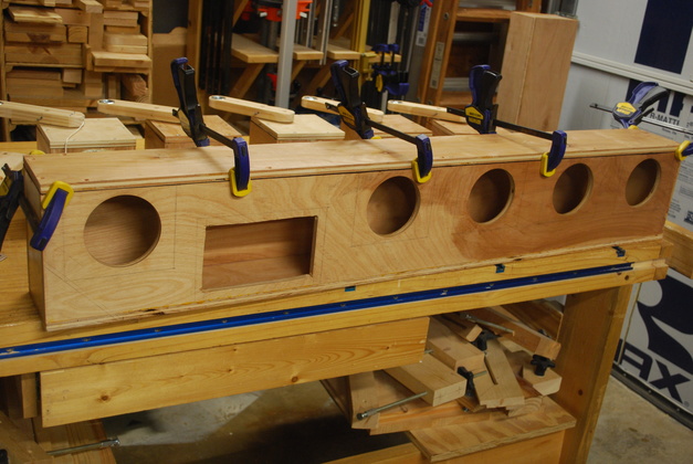
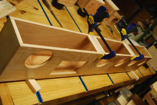
| Fitting front cover to the plenum, ready to drill screw holes. The clamps keep it squarely in place while I drill the screw holes. |
| Plenum mounting bars bored and counter bored. Also, in the rear, notice the felt gaskets for valve boxes and riser are installed on the plenum. |
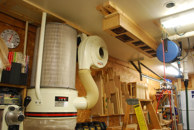
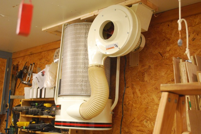
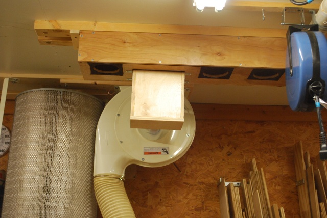
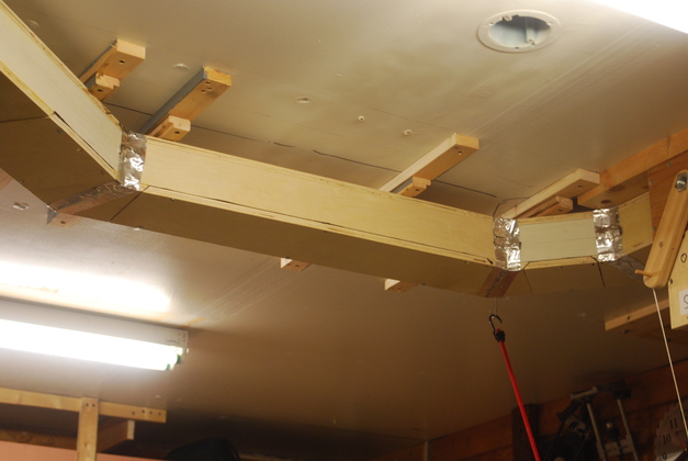
| Plenum on the ceiling showing relationship to the impeller and motor. |
| Here is a pic made late in 2015 when I removed the filter for cleaning, I also replaced the plastic cake plate cover with a plywood cover, easier to get into to clean the filter. |
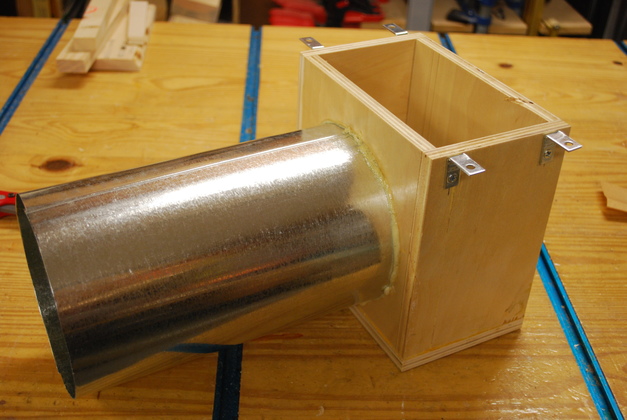
| Riser box being glued. |
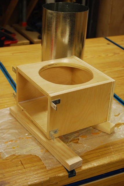
| Riser box being painted. You can see the 6" pipe just behind the riser box, this will be Gorilla Glue'd into the riser box and connect the riser to the motor/impeller's input. Also the mounting brackets are mounted, symmetrically, these didn't need to be staggered because the port for the riser is offset to the rear of the plenum. |
| Riser test fit on plenum. |
| Test fit side view showing 6" pipe from riser to motor/impeller. This also shows the relationship of the riser hole, in the plenum, to the valve holes. The valve boxes (holes) must be flush with the front of the plenum to allow the control bars free motion. |
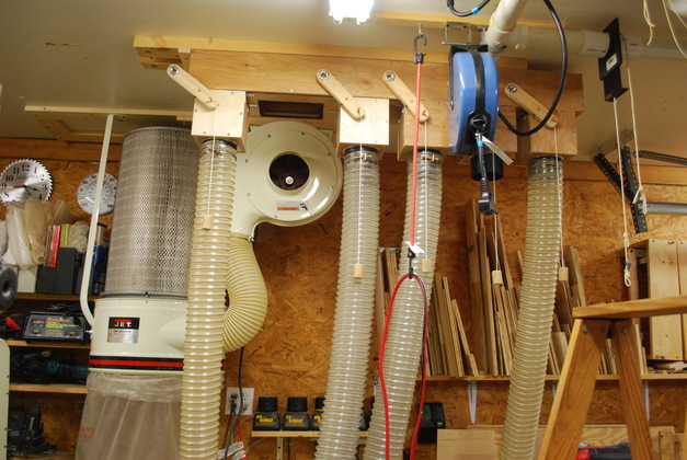
| Valves and hoses installed. You can see how the valve control bars are in front of the plenum. |
| 6" pipe being glued to riser. If you look closely, you can see the Gorilla Glue foam at the base of the metal pipe. Perspective makes the pipe look larger at the left end, but it's not. |
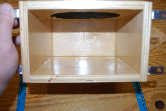
| Inside of riser, notice how slick and shiny all the interior surfaces are, thats good for wind and chip passage. Also note the pipe is flush with the inside surface of the riser, again, thats good for preventing turbulence. |
| Install complete. |
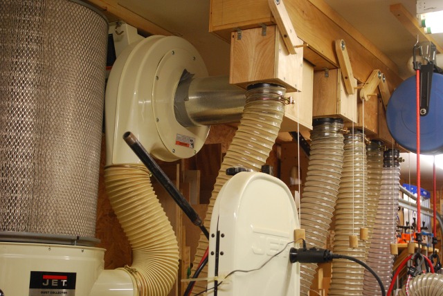
| Side of the competed install. You can see how the 6" pipe connects the motor/impeller with the riser and plenum. The 6" pipe really fits tight to the motor/impeller, but I'll probably duct tape that joint. All other joints are glued or have gaskets. You can also see how the valve control bars swing in front of the plenum. |
|
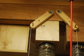
| The way you can tell which ones are on! |
| OFF | ON |
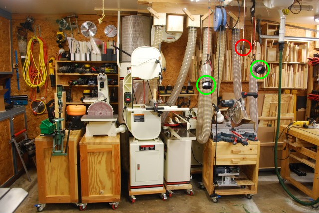
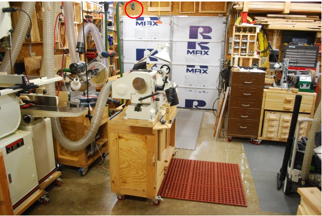
| The machine line. When I need to use a machine, I roll it out, flip on the vacuum for that machine, turn on the DC using the power fob (red circle) above my head I also roll the lathe over just under the power fob when its in use. Both the lathe and dovetail jig use one of the free hoses green circles. |
| The lathe, pulled out where I normally use it, connected to the center free hose, note the DC power remote in the red circle. |
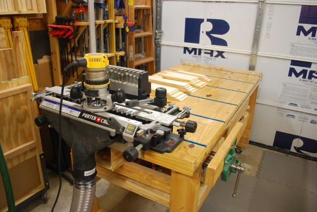
| Pic of the dovetail jig, mounted in it's normal place on the end of the workbench and connected to a free hose. |
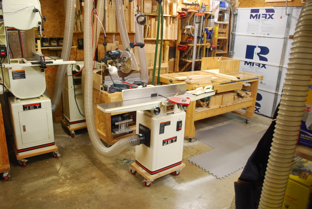
| Jointer using a free hose. |