| 
| 
| 
|
|
| |||
|
|
|
|
|
|
| |||
| Data Terminal Index | Prototype | Circuit Board | KeyPad Lcd Sketch |
| Schematic | PCB Drawing |
My objective in this project is to have a dumb terminal to use with Arduino projects. By dumb, I mean the terminal is a simple input/output device, it only prints from the host to the LCD and only sends characters from the keypad back to the host. We used a lot of these back in the early days of electronics, I even built a few. I can use this on almost any project which needs to have human input/output without a PC being present.
Cabinet
I eyeballed the main components, LCD and Keypad and sketched up a data terminal housing.
I wanted the LCD at about a 45° angle so it would be easily read, and the keypad at 7° or 8°.
PCB & Cables
Last year I bought a package of 30 Double Sided Prototype PCBs for $10, this PCB (50mm X 70mm) is from that package.
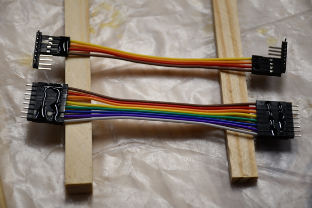
I'm going to make some 2.54mm (.1") pitch Dupont cables for the Expander to Keypad (8 pin), and Nano ot LCD (4 pin), which should make it easy to remove or replace parts.
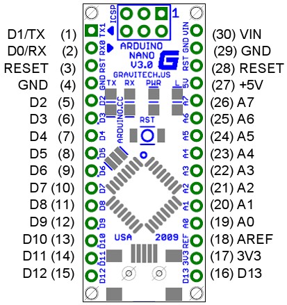
The Nano will be on two 2.54mm pitch (.1"), 15 pin, header strips and the I/O Expander (for Keypad), and the I2C cable to the LCD, will both be on 4-pin headers.
A single pin will be needed for the interrupt from the I/O Expander to the Nano.
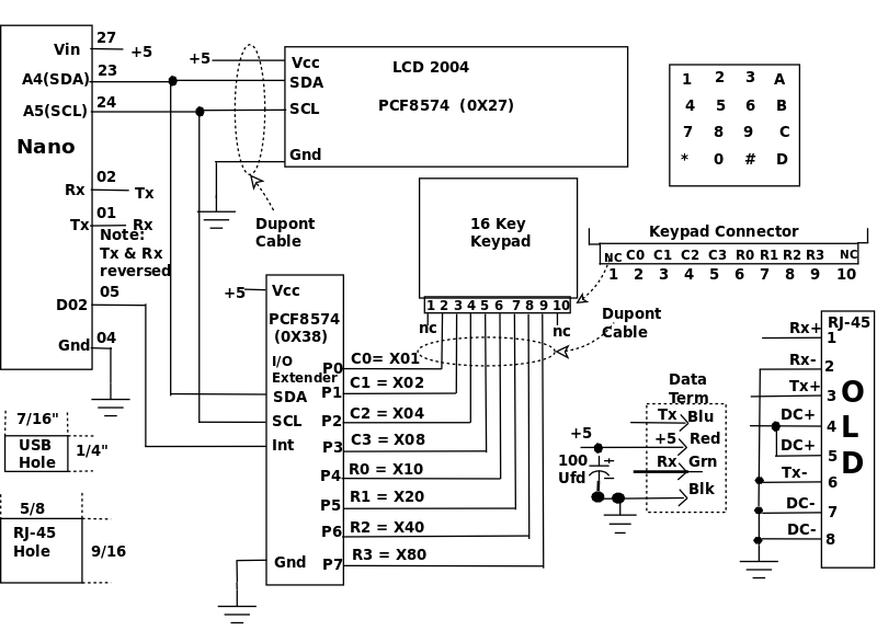
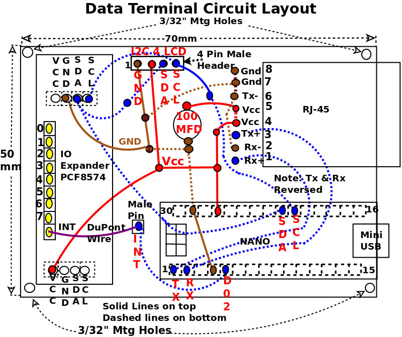
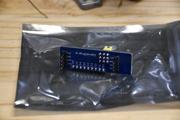
Please note, the pinout on the LCD PCF8574 is not the same as the pinout on the I/O Expander PCF8574 (Vcc and Gnd are swapped).
BTW, I spent about $35 on this terminal, buying things in small qty.
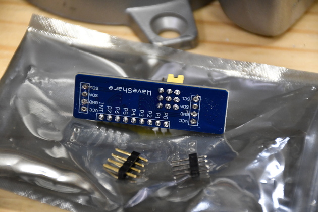
I first thought of just plugging the male pins on the end into a header on the PCB, but that isn't very mechanically stable, so I decided to plug both ends into female headers on the PCB. Crappy thing, none of these come without headers so I had to replace them. I replaced the male pins and female socket on each end of the PCF8574 with downward pointing male pins. The RJ-45 came mounted on a breakout pcb with a row of 8 holes at it's rear. I passed #26ga buss wire through each of the 8 hles and soldered the end into pades on the etched board. That made a pretty secure mounting for the connector.
In the future, I'll mount the PCB on the case bottom, it'll be much easier to work on. I'll also use a 4-pin flat cable with JST connectors for the link to the Dust Auto system, the skiz below reflects that change.
| 1 | 2004 LCD | $9.00 |
| 1 | HEX KEYPAD | $9.00 |
| 1 | Arduino Nano | $4.67 |
| 1 | PCF8574 I/O Expander | $3.50 |
| 1 | PCB 70x50mm | $.50 |
| 1 | RJ-45 Connector | $.82 |
| TOTAL | $27.32 |
It has recently (Aug. 2021) occurred to me that I could make a battery powered FR interfaced version of this for home control. The terminal only draws about 22MA, not counting an RF link), there are some rechargable batteries available, in expensively, that would easily hold this terminal up for 24 Hrs.
|
|
| PCB Drawing
| Nano Pinout
|
|
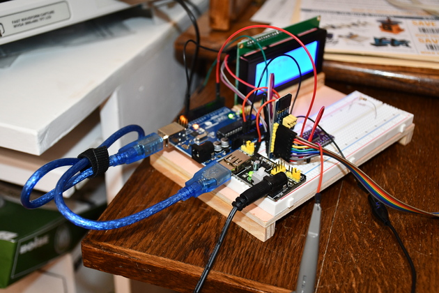
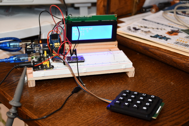
Terminal breadboard, atcually just keypad & LCD.
I'm using an Uno for the breadboard, the finished model will use a Nano, shouldn't be a problem.
You may notice the analog mux pulgged into the breadboard's center, it is not used here but will be for the final automation project to multiplex analog inputs from Isnsrs (Current sensors).
|
|
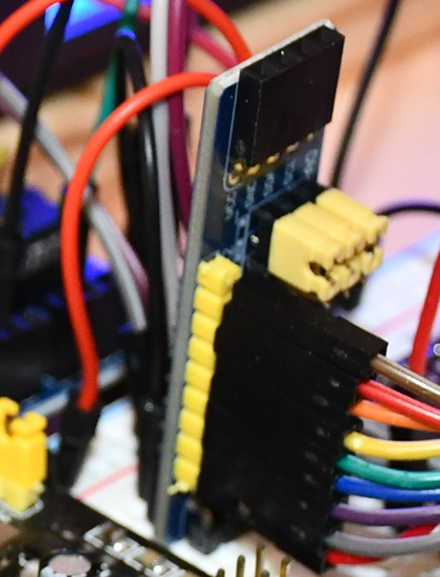
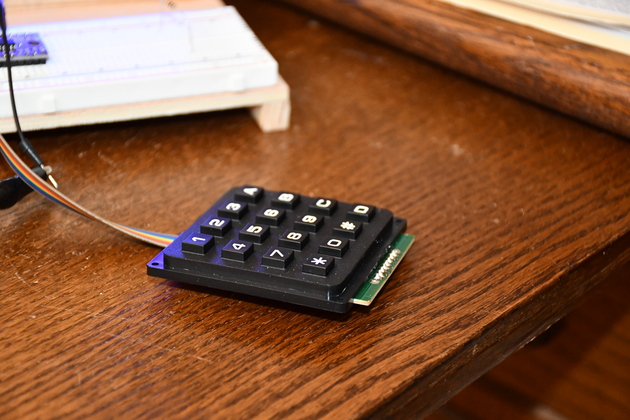
The keypad, has a nice feel but nasty switching (the software debounces it). I checked with an oscilloscope and there is a quiet spot after the initial switch noise, about 2MS out, so I put a 2MS delay before I read. Note the 8 wire Dupont cable from the keypad to the PFC8574 on the breadboard. |
|
A pic of the keypad installed in the cabinet, you can see how I used an angled header so the cable is easy to install. |
|
|
|
Here it is after soldering in straight headers. |
|
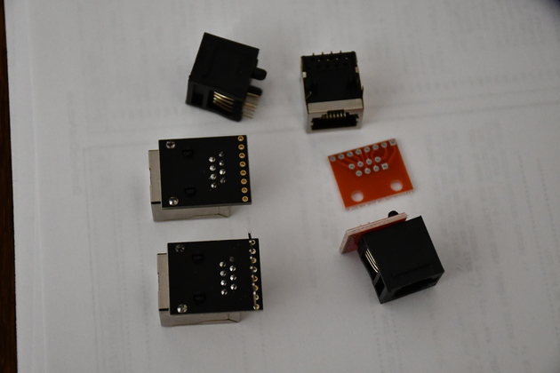
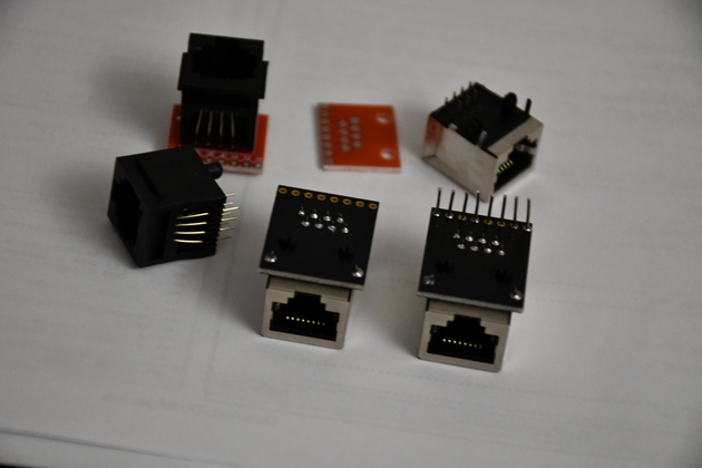
The RJ-45 connectors I used on both ends are just RJ-45 sockets mounted on a small PCB that makes the pins (1-8) come out spaced at .1" apart, suitable for breadboards and most pre-drilled pcbs. You can buy the complete assembly (lower left) and solder short wires into the 8 holes, or buy separate socket and pcb. Note you can get the sockets facing horizontal or vertical. |
|
Different angle. |
|
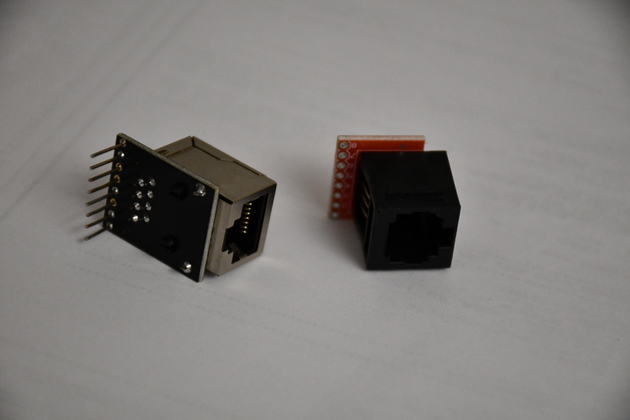
The two most common, note jack points horizontal (left) or vertical (right). I soldered 7/16" 22 AWG tinned wire into each of the 8 pins so I could plug it into a breadboard or pre-drilled pcb. The one on the right is a pcb I bought with a vertical RJ-45 snapped into it. |
|
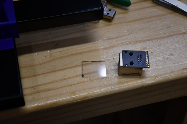
The RJ-45 with it's mylar insulator. I'll glue the mylar under the RJ-45's position on the PCB to prevent any shorts to the RJ-45's pins underneath. |
|
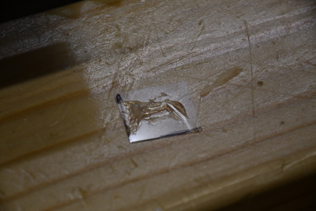
RTV silicone smeared on the mylar. |
|
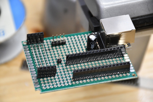
The PCB with all headers soldered.
Note I used buss wire across the PCF8574's connectors.
The data terminal's pcb layout, the two 4 pin female header (on left) are the I2C for the I/O expander to the Keypad and the 4 pin male header (top center) is for the I2C cable to the LCD.
The male single pin header is for the keypad interrupt from the I/O expaner.
|
|
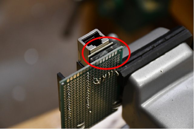
Note, you can just barely see the mylar strip (Red Oval) under the RJ-45 connector. |
|
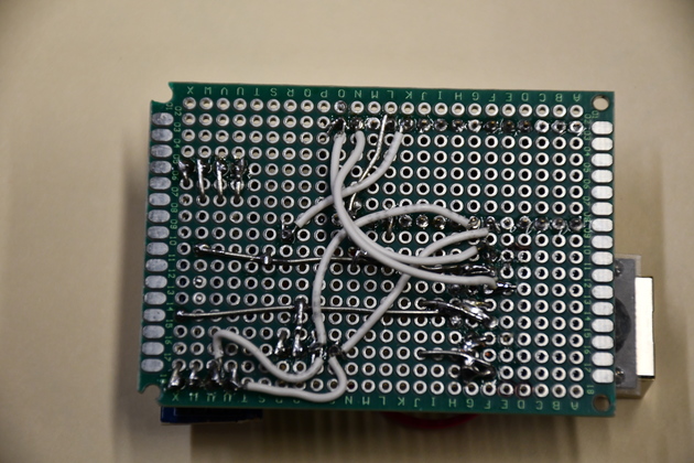
All grounds, vcc busses, and all the signal wires in. One of the keen things about this data terminal, it doesn't need many discrete wires (7) to make it work. It would be pretty easy to etch a PCB for it. |
|
|
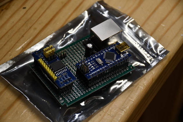
And with the chips plugged in, ready to mount in the cabinet.. |
|
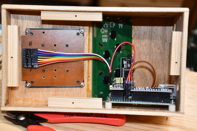
Bolted down in the cabinet with cables connected.
You can see the nylon standoffs under the PCB.
|
|
|
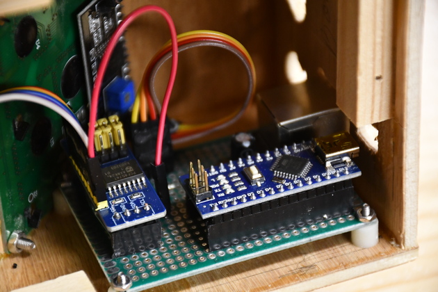
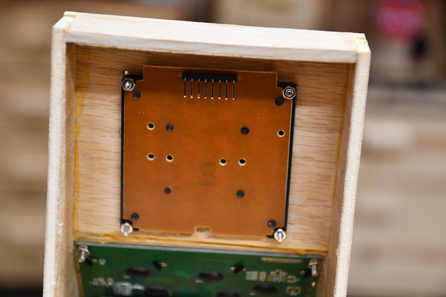
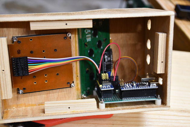
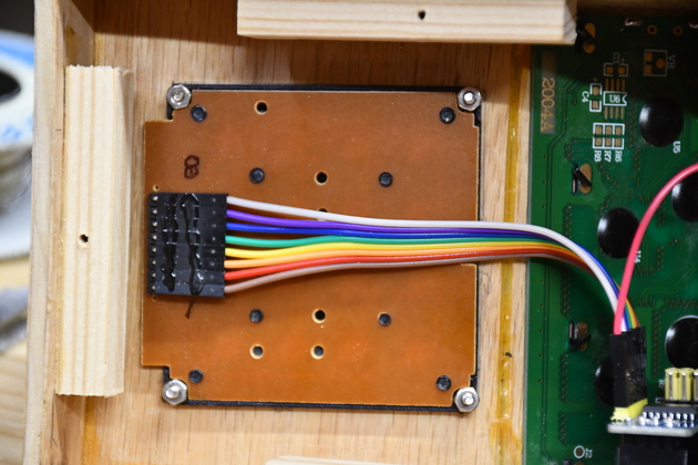
Closer pic of PCB installed in cabinet, the red Dupont wire in the foreground is the interrupt line from the I/O Expander (on left) to the single pin header on the PCB. The slightly out of focus 4 wire cable in the backgound goes to the PCF8574 on the LCD. You can see the 2-56 machine screws and nuts holding the board down. For comparison, note, on the far left, the 4-40 screw holding the LCD in. |
|
The 8 wire Dupont cable from I/O Expander to the keypad. |
|
|
Completed interior of data terminal. |
|
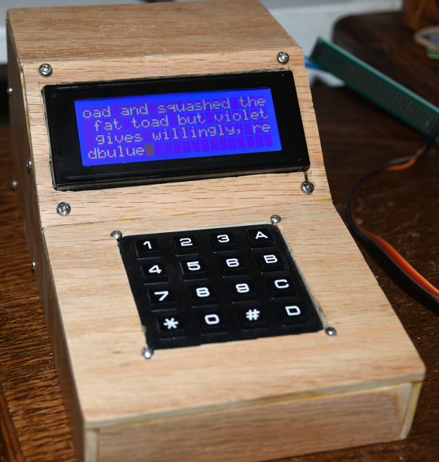
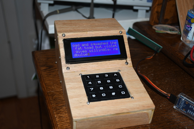
Completed data terminal being tested. |

|
|