Network Cabinet
I haven't done any woodworking in 5 years so please excuse some sloppyness!
Once Upon a Time, Bill and I ran a very small internet hosting and security company called "Linux Castles".
We needed several computers to handle the traffic, a Firewall & gateway, nameserver, html, and mail server.
We bilt these computers in a "Blade" format. We had several "Blade" computers in this cabinet and this
was called the "Computer Console".
But as time passed and the network changed and grew, the cabinet requirements also changed.
In 2023, while I was adding CCTV security cams, I decided to remodel and rename it "Network Cabinet".

We still have numerous computers in the office now:
	Gateway (Firewall)
	My Workstation
	Cams (host the video surveillance system)
	Win (only windoze computer in the house runs turbotax once per year).
KVM
I use a KVM to manage multiple computers, so I no longer need a console (monitor, mouse, and keyboard)
I bought a MT-VIKI KVM Switch 4 Port, HDMI KVM from Amazon
It took a little finagling to get everything working like I wanted.
I had to buy 4 EIDE adapters so when I switched to a different computer for a while, then
switched back, my mouse and keyboard worked.
I also had to buy several extra cables (USB, HDMI etc).
3 of the 4 computers were in the network cabinet, but my work station is beside
it and required 10' long cables so I could roll the nework cabinet out to get to
it's back for maintenance.
|
This cabinet is being build from 2x10 SYP (Southern Yellow Pine), cut to
length, resawn, then planed.
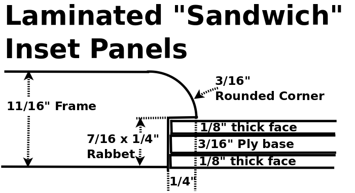
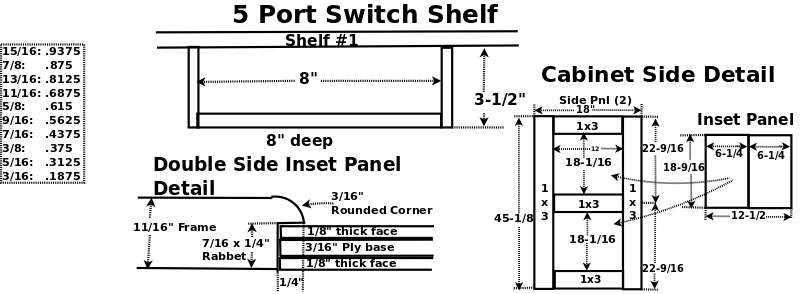
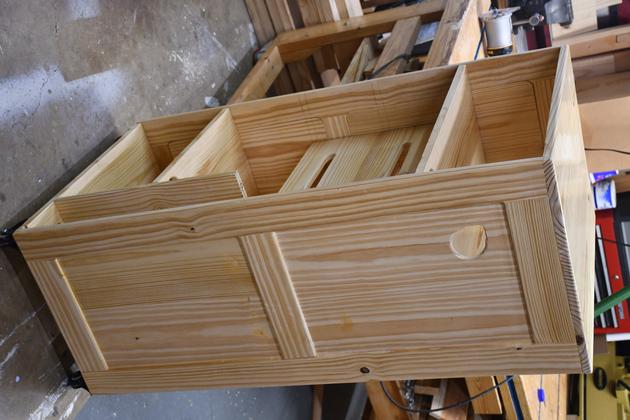
I'm using inset panels on the sides, these are a laminated sandwich of 1/8"
faces on a 3/16" base.
Because this cabinet's interior will be open, BOTH sides will have
pine faces.
A 7/16" rabbet is cut so the back side will be more or less flush.
This diagram shows detail of inset "Sandwich" panel and rabbet.
BTW: I use TiteBond II glue.
The only problem with doing this is I don't cover up the crack around the inset
panel on the inside!
|
UPS Upgrade04/29/2024
We have had numerous power failures (Oncore), since the new cabinet has been
in use.
Oncore (power delivery co.) has been having a lot of problems lately, probably
a push for raising rates.
I observed:
Network failed immediately
CCTV stays up longer.
Gwy fails quickly.
I did some research to determine UPS wattage capacity.
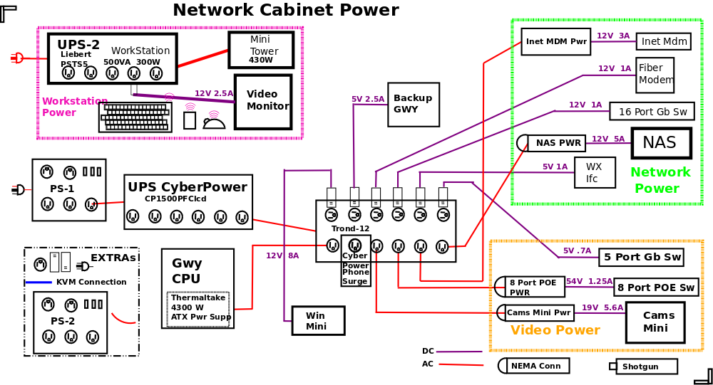
I researched UPS systems, initially replacing the 3 systems We had, and adding
PFS (Power Fail Soon) detection and broadcasting, so all CPUs and NAS can gracefully power down.
I decided that it would be simpler to use a single UPS, so I began researching.
I had determined, early on, that I would need about 1KW to allow everything to
power down gracefully.
One of the things I looked at was communication from the UPS to computers.
It appeared only 1 system would be alerted when the main UPS issued PFS so I
would need a way to broadcast to the other CPUs.
Found NUT, and the Setting's Power application (Ubuntu).
I chose the CyberPower CP1500PFCLCD PFC Sinewave, which delivers 1KW and talks
via USB to my Ubuntu 22.04 (soon to be 24.04).
The promary problem is, its too tall to fit into the network cabinet! I didn't
like the UPS which would fit.
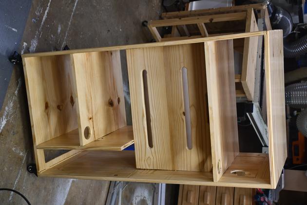
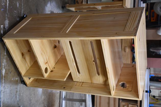
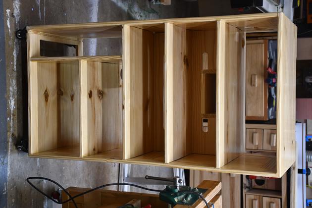
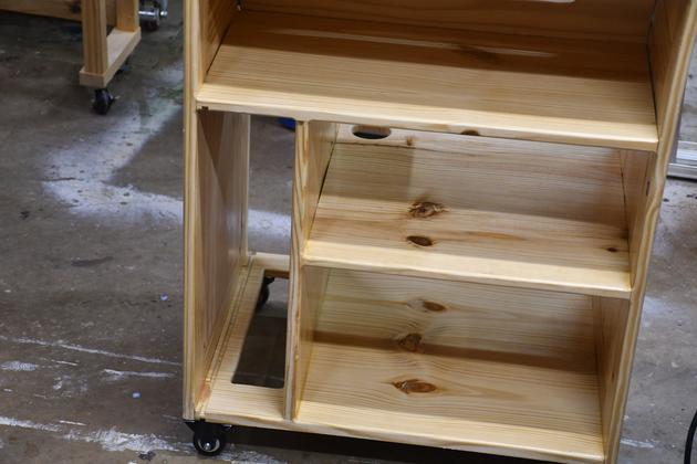
I decided to cut out a section of shelf 4 for the CP which is 14 x 3.9 x 11"quot;.
Make It Fit
I wanted to retain the printer paper storage (11-3/4" wide), so I'll saw
a notch out of shelf #4.
Shelf 4 is 16-15/16" wide, which leaves 5-3/16", the UPS is 3.9"
wide, so there is 1-3/16" clearance. The UPS takes in air via a slot in
the rear, and expells warm air via side grills. hence it needs to have clearance
on both sides if possible, so it will have about 19/32" (little over
1/2") on each side except at the right top where it will have several
inches.
I can't leave shelf #4 hanging, so I'll add a 3" wide vertical support to
the bottom of shelf #3.
BTW: I keep a ceiling fan running 24 hours during warm months.
Broadcast Fail Soon
When the server gets the Fail Soon message from the UPS, it will need to notify
all the other CPUs. It might even be needed to send Power Down messages to the
CPUS individually, in case some need or can be powered down earlier.
PFS (Power Fail Soon)
There are anumber of ways to shutdown computers and NAS:
SNMP: message (trap??).(TCPIP Illustrated: snmp_sim.htm#25_0)
upsAdvControlRebootShutdownUps trap (.1.3.6.1.4.1.318.1.1.1.6.2.2)
USB: message
TCP: via network and home coded client server.
wb-mqtt-apcsnmp (Debian):
NOTE from community.de.com
using upsBasicControlConserveBattery (.1.3.6.1.4.1.318.1.1.1.6.1.1.0)?
I ask because the UPS is slightly different from a computer -- the
computer's decision to turn on does not depend on how it's turned off,
but the UPS distinguishes between a command to turn off (does not
turn back on) and one to turn off and then back on (called variously
"Shutdown w/ AC restart", "Conserve Battery").
See: "https://github.com/wirenboard/wb-mqtt-apcsnmp/tree/master/debian"
TCP Ill.: "http://localhost/Computer/Network/tcpip_ill/snmp_sim.htm#25_0"
| Click for Larger Pic
|
|
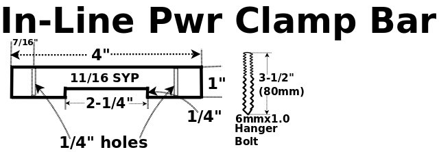
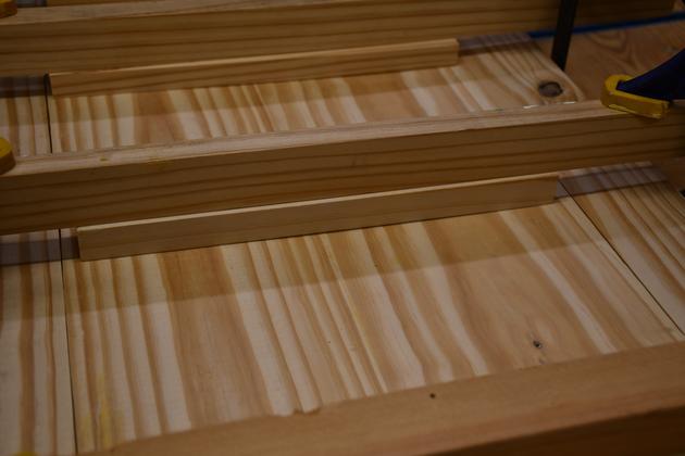
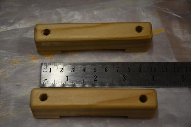
This little wooden clamp bar will hold the power supply modules in place.
|
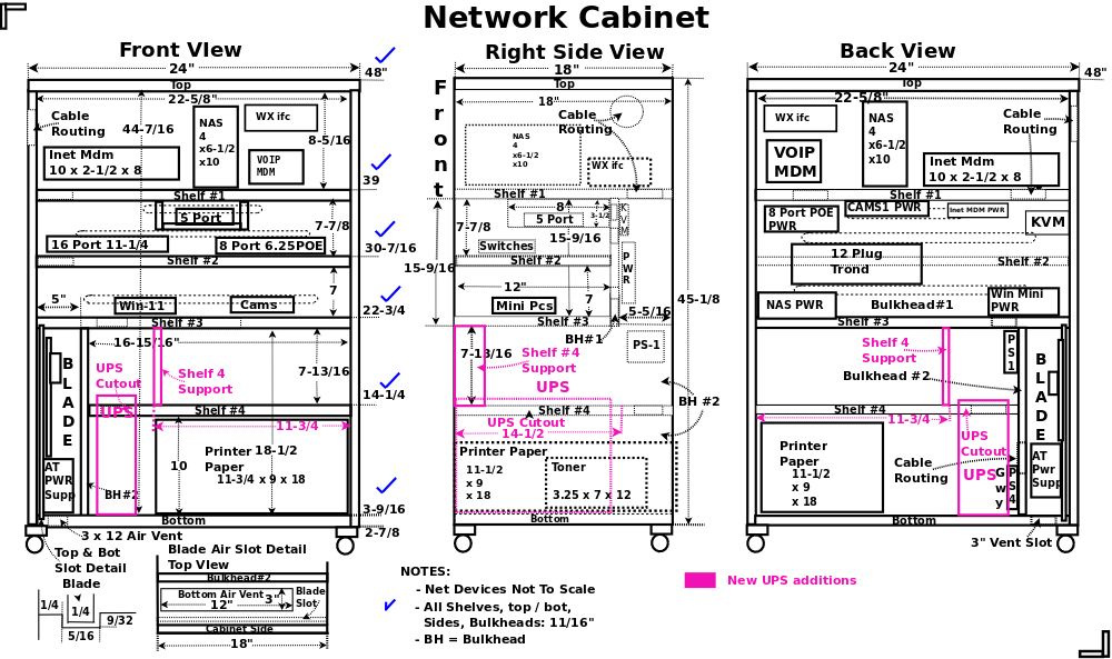
In the above diagram, notice there is no back on the cabinet, because the
equipment needs all the air flow it can get.
BH (Bulkhead) #1 and the shelves give it rgidity.  Also, BH 1 is a great
place to mount small power supplies and plug strips.
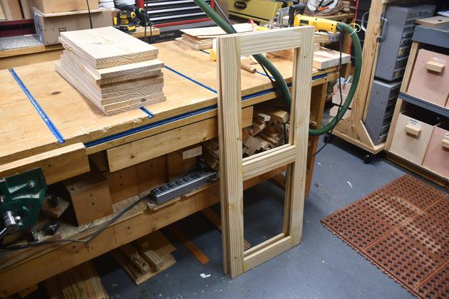
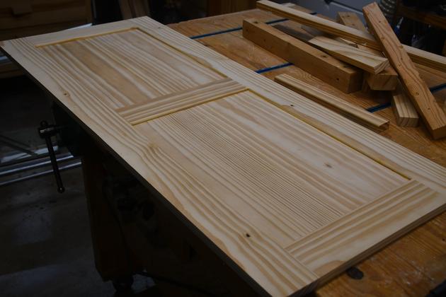
Side Frame
|
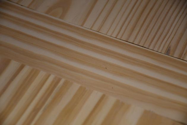
The side frames glued and sanded.  Each jiont has one #20 biscuit
in it.  These were cut to length from 2x10 SYP, then resawn planed,
 slotted and glued.
|
|
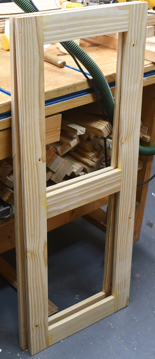
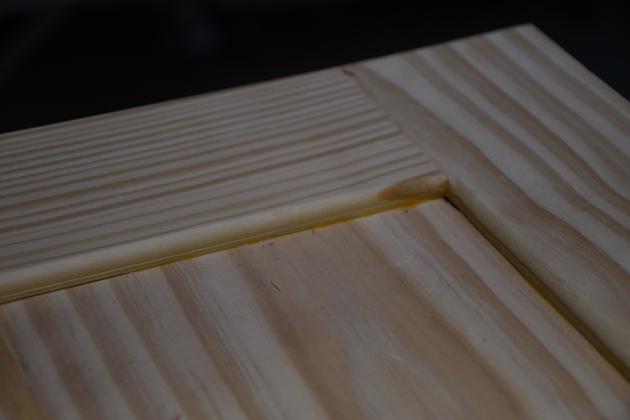
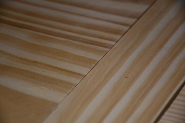
Closer look at the side frames, sorry I didn't get pics of their assembly.
This is before any rabbet or round overs.
|
|
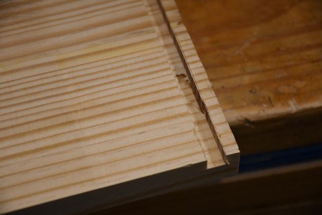
Inside of a side frame showing the rabbet for the inset panels.
This is 7/16" to allow for two 1/8" SYP panels plus one
3/16" ply center.
|
|
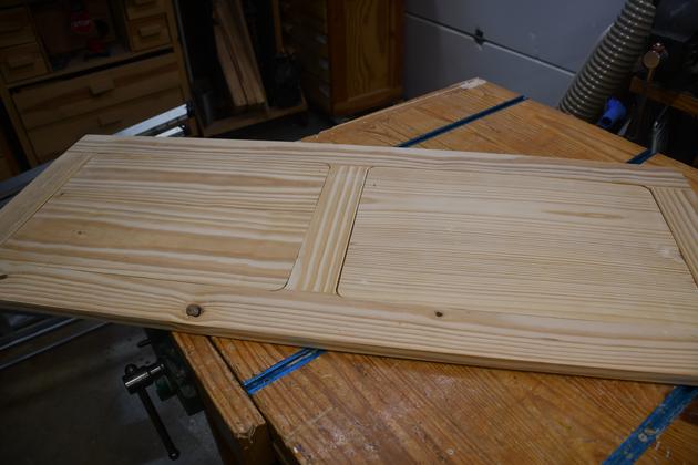
Outside of side frame showing round over for inset panels.
|
|
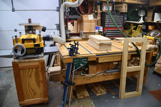
Planing the resawn shelves, top, bottom, and BH (bulkhead) panels.
I'm using my DeWalt DW735 planer, I used to have a Jet JPM-13CS,
which was a terrific planer, but I no longer have room for it.
|
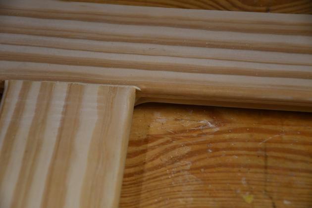
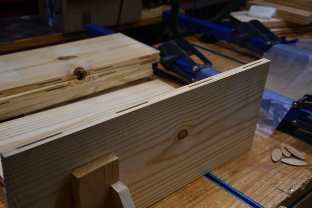
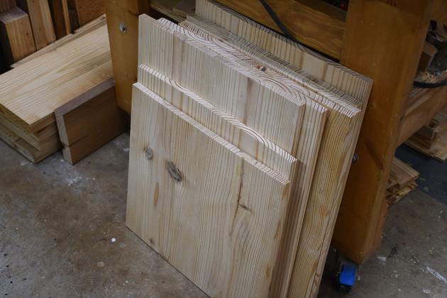
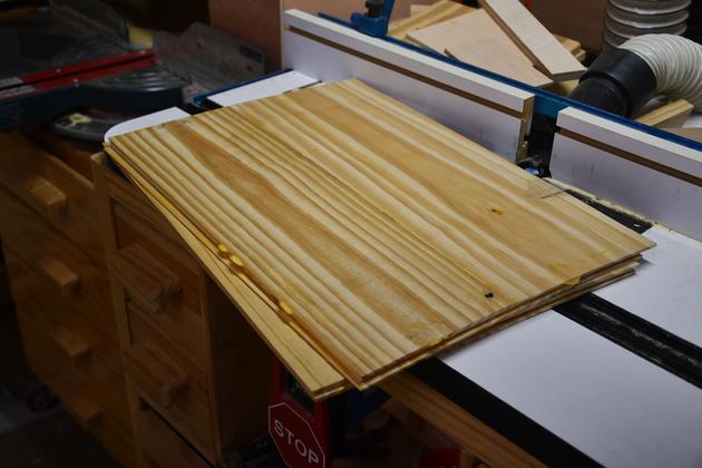
Edge Joining Shelves
|
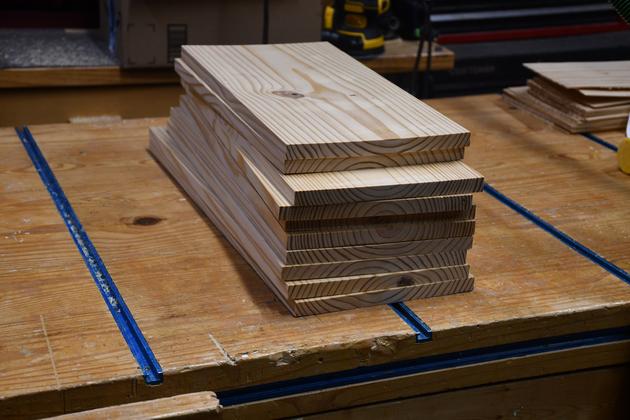
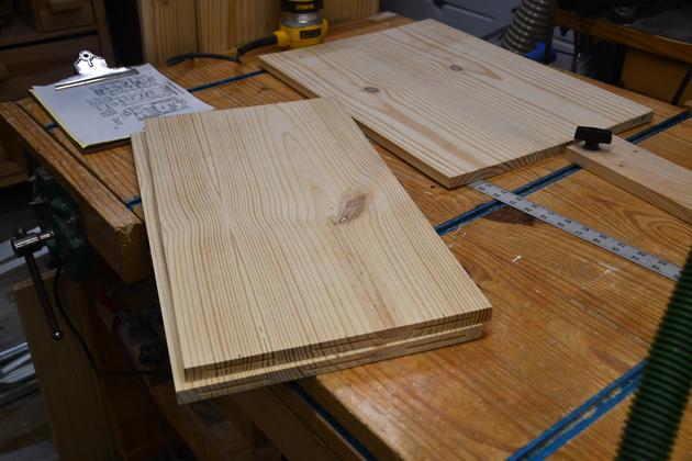
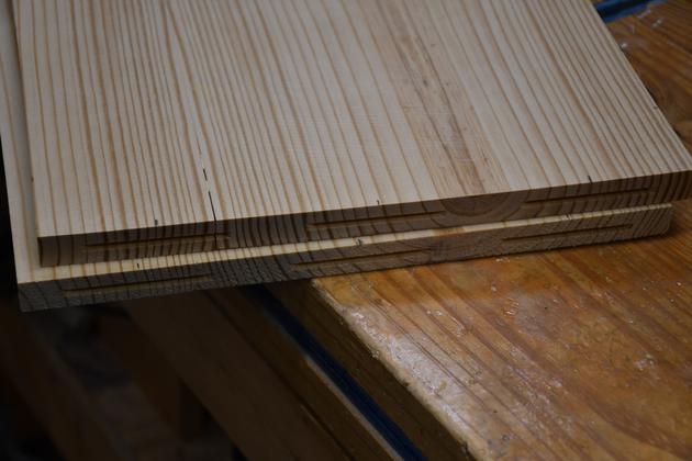
Shelf, top, bottom, and BH (bulkhead) cut to length, resawn, and
planed, 11/16 thick.  These have also been run across the
jointer so they will edge join with no crack.
|
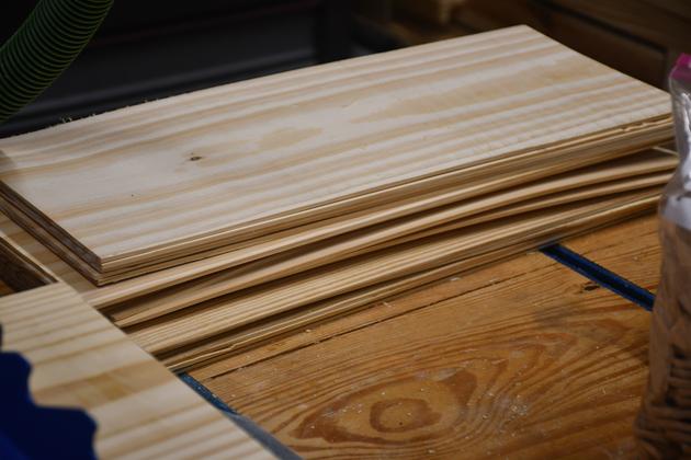
|
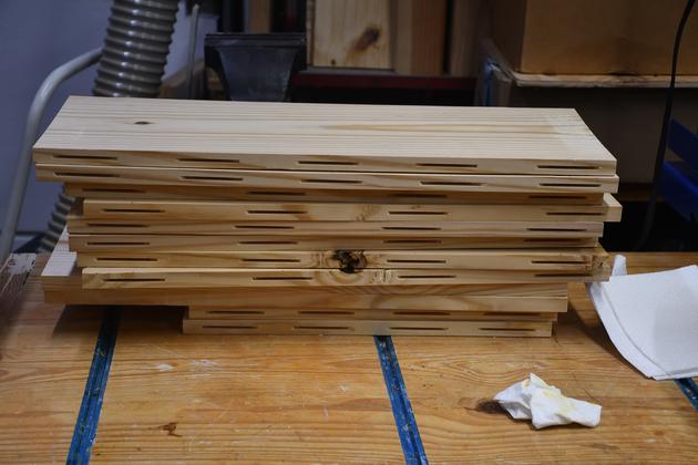
Shlef pieces slotted for biscuits, ready to glue.
Since SYP (Southern Yellow Pine) likes to warp
and cup, I use biscuits generously to prevent this.
|
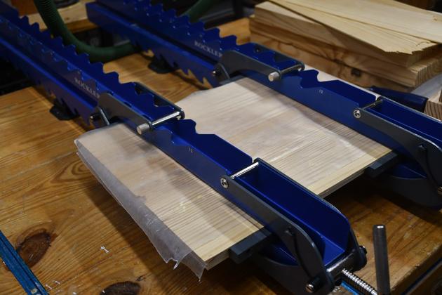
|
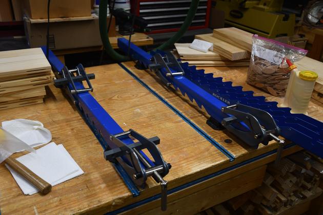
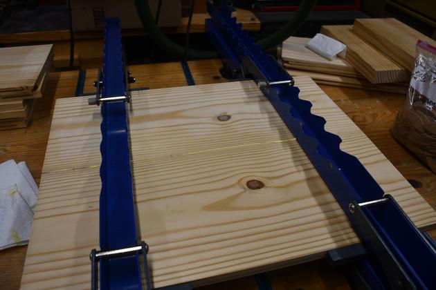
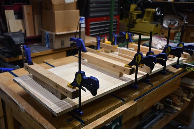
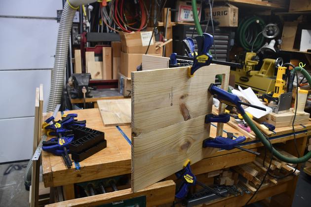
Panel clamp ready for next panel.
I'm using the Rockler Panel Clamps for the first time.
They do a great job keeping the panel edge
pressure while keeping the panel flat.
These can also be used for edge joining 1/8" panel inserts.
|
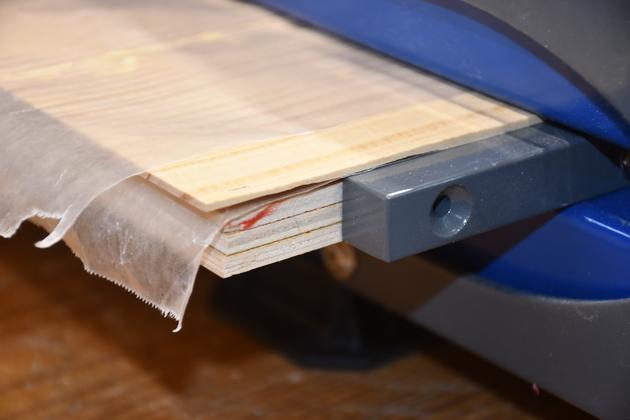
|
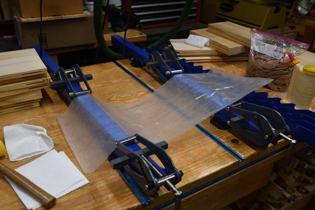
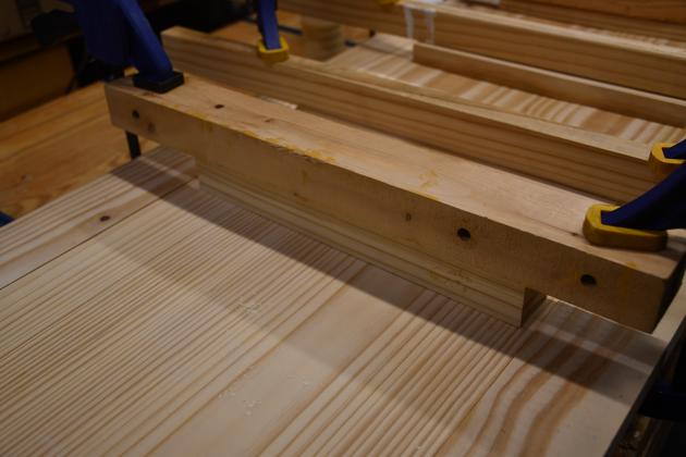
I remove the top bar then lay a piece of
wax paper across the bottom bar of the clamp
to keep squeezout off.
|
|
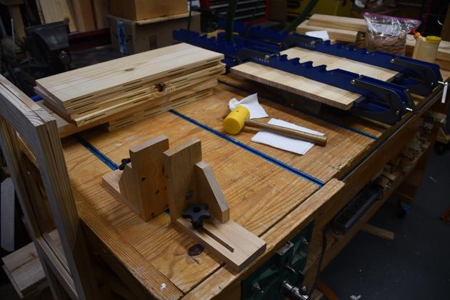
Note
the two little 'L' brackets, these are for holding one
of the panels to be edge-joined, while applying glue
and biscuits.
I built the work bench about 20 years ago, the tee
tracks have been invaluable.  I have a number of
brackets/tools that use them.
You'll see these used again when I laminate the
inset panels.
|
|
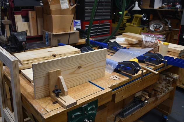
Section of the Next panel, between the "L"
brackets, ready to glue.
|
|
Closer look at the biscuit slots.
|
|
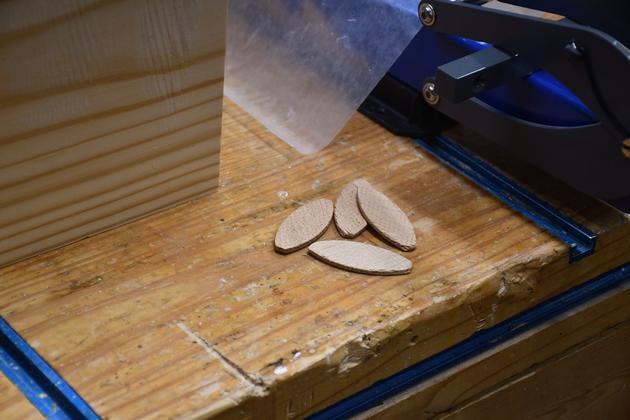
#20 biscuits ready.
|
|
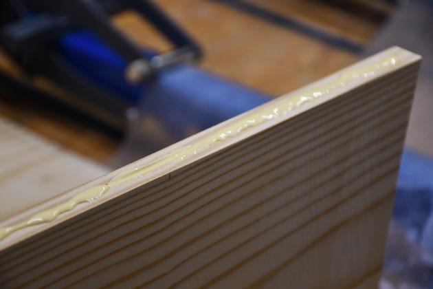
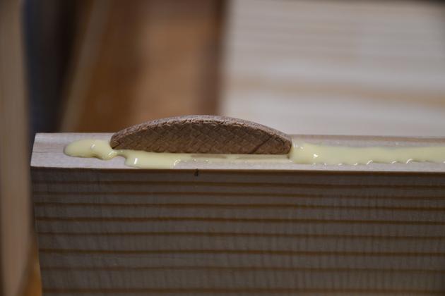
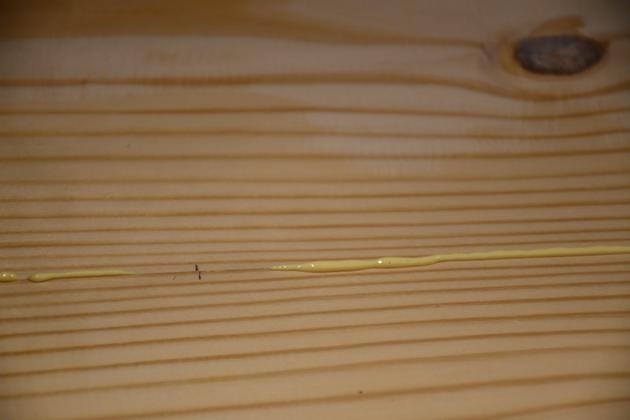
Glue bead on the edge.
|
|
Biscuits tapped into their slots.
|
|
Close look at a biscuit in it's slot.
|
|
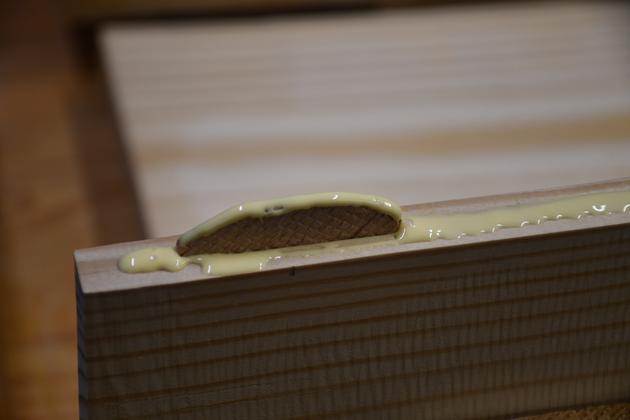
Bead of glue on top of the biscuit.
|

|
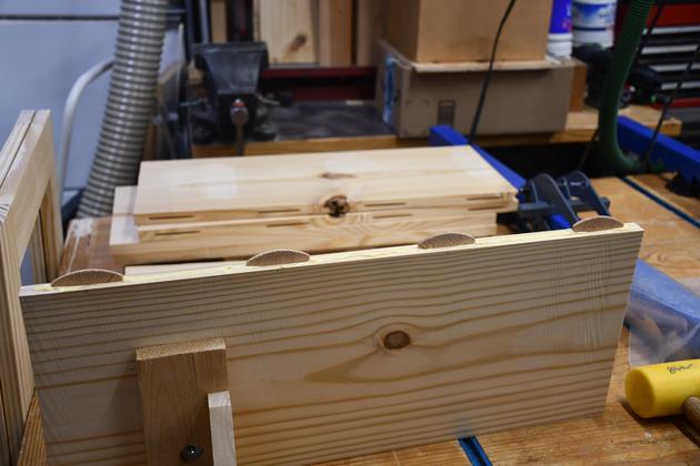
Second panel section in place with
biscuits inserted partially. As I
close the crack, I also line up
the edges.
|
|
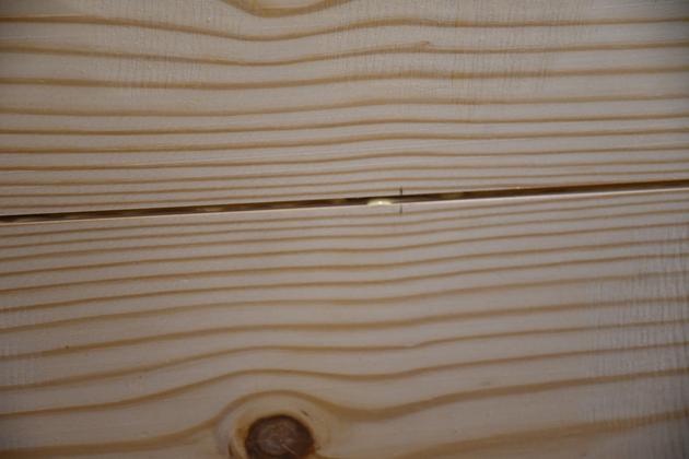
Closer look at edges to be joined, note the "tic"
mark for a biscuit slot.
|
|
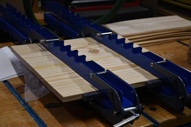
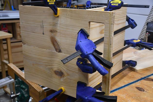
Panel sections on the bottom clamp bar.  Top
clamp bar is not yet in place.
|
|
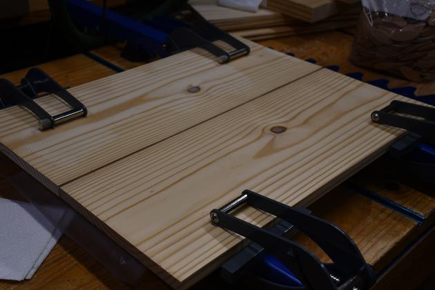
Top clamp bar in place and pressure applied.
|
|
Note a little squeezout. I'll wipe it off
and let the glue set.
Also note the little "tic marks"
thats where one of the biscuits is.
|
|
This will be more important when laminating
the 1/8" pine faces to the 3/16" plywood base.
|
|
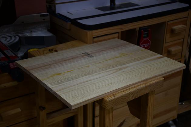
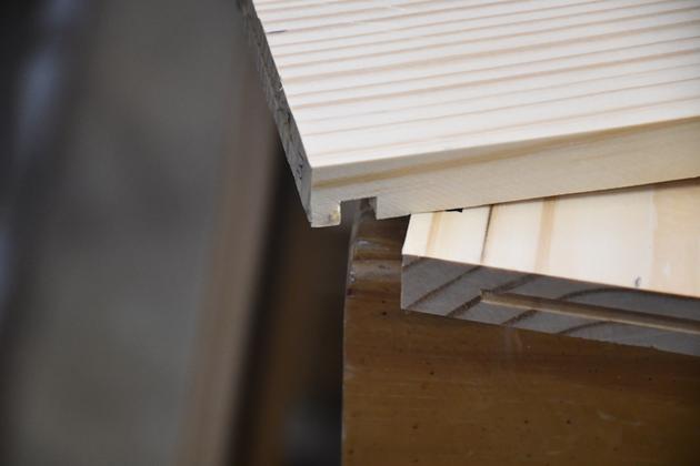
Bottom of a glued shelf before sanding. You can see a little
glue squeez out.
|
|
All shelves and builkheads glued and sanded.
|
Inset Panels
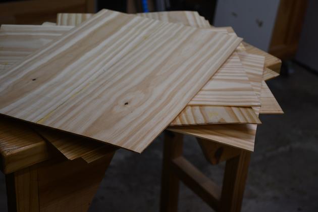
|
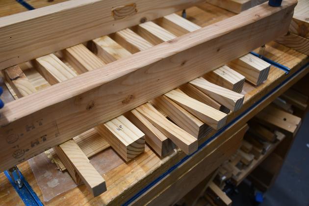
These are the 1/8" thick pine faces for the inset panels.
The Dewalt DW735 won't plane this thin so I have to use a
planing Sled.
For more info on making these, please see Resawing
and Making Inset Panels.
|

|
Another angle of the 1/8" thick panel faces.
|
|
Edge joining 1/8" SYP panel faces for insets.
|
|
Because the Rockler push bars are 10mm square, I needed to raise
the 1/8" panel to get pressure on the edge and top, from the
Horizontal pressure bars.  You can see the ply panels I used
to do this.
|
|
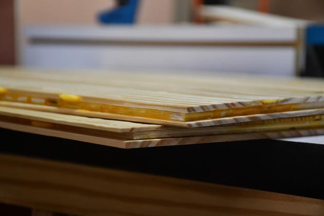
1/8" SYP panel faces after edge joining..
|
Laminating Inset Panels
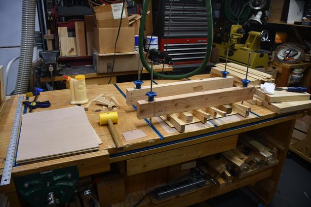
|
This is my simple laminating set-up on the work bench.
I use extended tee bolts in the tee tracks imbedded into the work
bench surface to put pressure on the pieces being laminated.
BTW: the knobs are
Rockler quick release knobs
|
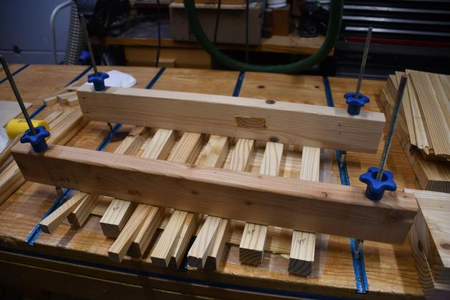
|
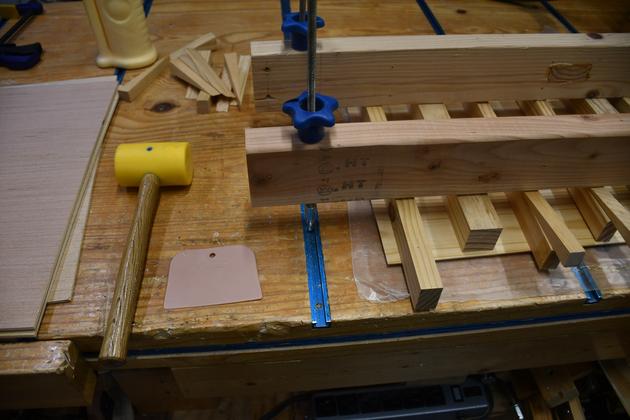
Closer look at my lamination set-up.  I ripped these pressure bars
from one 2x10 so they would be near the same thickness.  Since all
the pressure bars are exactly the same thickness, I use small wedges,
driven between pressure bars and the top bars to get the pressure
uniform.
|
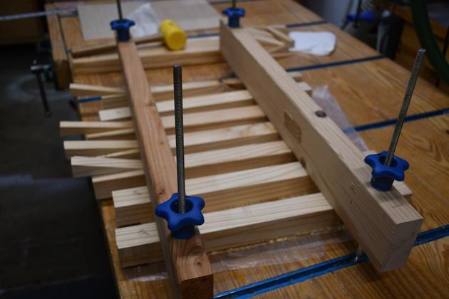
|
From the side.
|
|
Closer look at the wedges.
|
|
Kind faced hammer for tapping in the wedges, and glue spreadder.
|
|
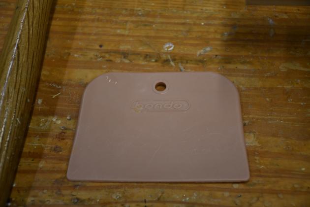
This is my glue spreadder, actually a bondo spreader from Walmart.
|
|
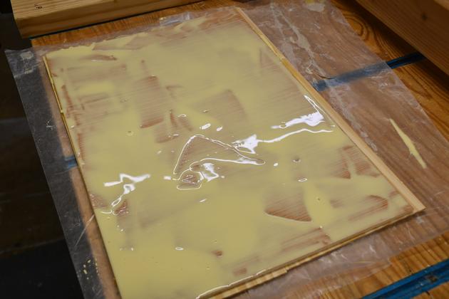
3/16 ply with glue spread, ready for SYP face.
|
|
Laminated panels.  The SYP faces are larger than the ply base.
These will be trimmed down to the base size and have their
corners rounded, to fit the side frame rabbets.
|
|
Edge view of laminated panel, not perfect but they will
look OK.
|
Side Assembly
|
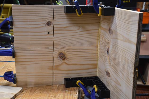
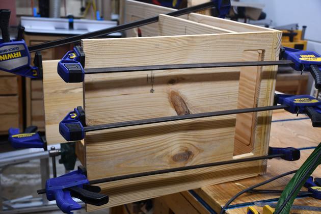
Gluing in the inset panels.  This is the right side frame piece
with both inset panels being glued.
|
|
Closer look at the way pressure is applied to the panel as it's glue
sets.  Remember the panel is a lamination of two 1/8" thick
pine faces to a 3/16" ply core.
|
|
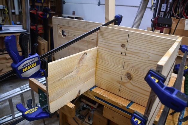
Another angle on the pressure points.
|
|
Right side piece with inset panels glued.
|
|
Close look at the glued in panel and the roundover on the front.
|
|
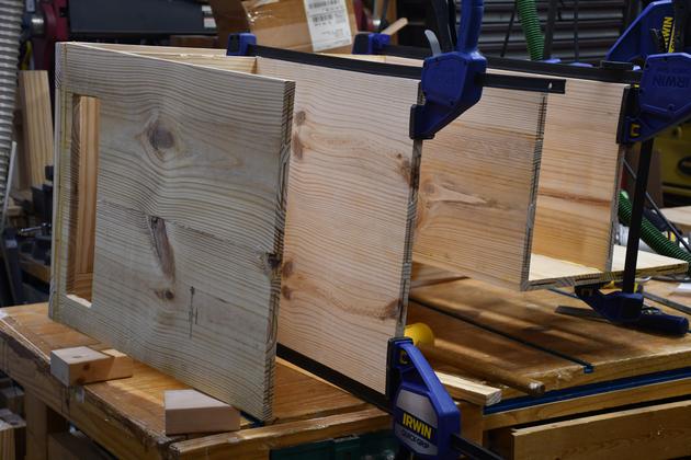
Back side of the right frame piece, the back of the laminated
panels is flush with the frame.
|
|
Closer look at the back side showing the inset panel is flush
with the frame.
|
|
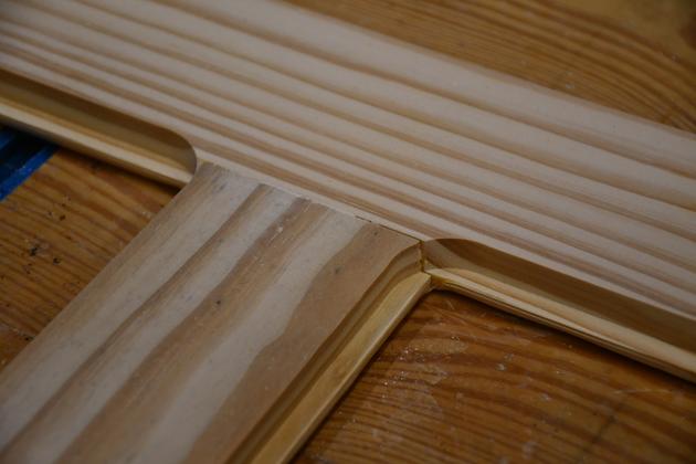
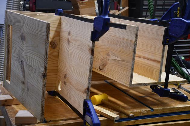
Looking at the center horizontal and it's adjacent panels.
Yes, there is a small visible crack but this is the inside
of the cabinet.
|
Main Frame Assembly
|
Blade slot cut in bottom. You can see one of the
biscuit slots. The top of the biscuit should be
just below the blade slot bottom.
|
|
Tennon slots cut into edges of shelves 2 and 3.
|
|
Closer look at tenon slots in shelves 2 and 3.
|
|
Blade slot cut into edge of shelf 3.
|
|
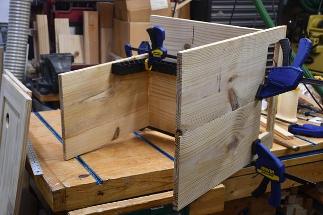
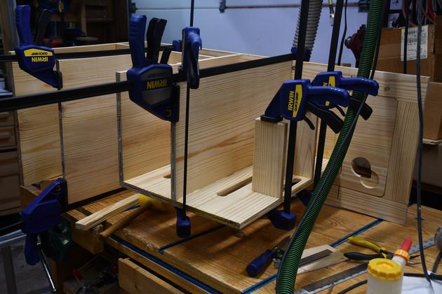
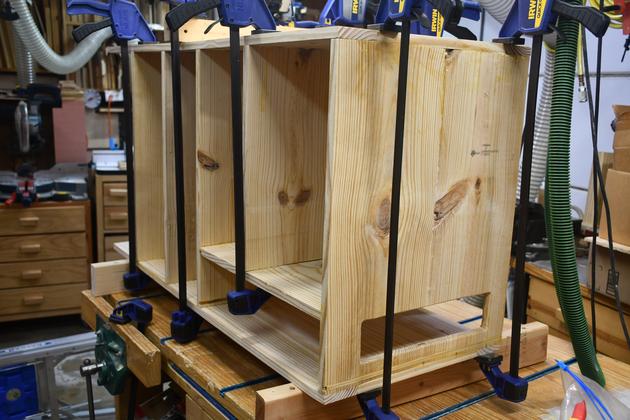
Bulkhead #2 being glued to the bottom panel (foreground).
You can see the blade's air hole on the right.
|
|
BH 2 being glued to bottom, from bottom left side of cabinet.
|

|
From left side, you can see the blade's air vent in the bottom.
|
|
Cabinet bottom on the right, looking straight at BH #2 (bulkhead).
You can see the shelf #4 biscuit slots, in BH #2.
|
|
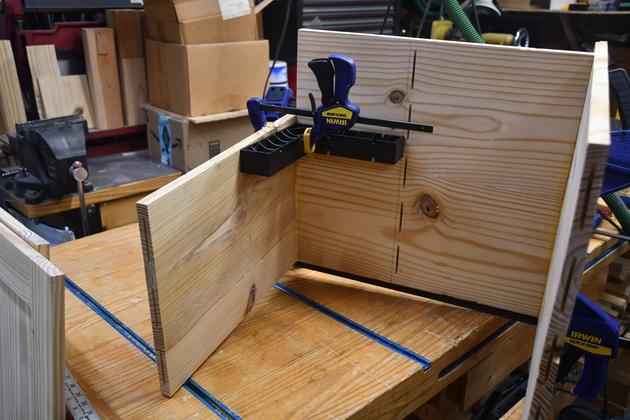
Shelf #3 being glued to the top of Bulkhead #2.
|
|
Diff angle of shelf #3 being glued to BH #2.
|
|
Left side of BH2 as shelf #3 is being glued.
|
|
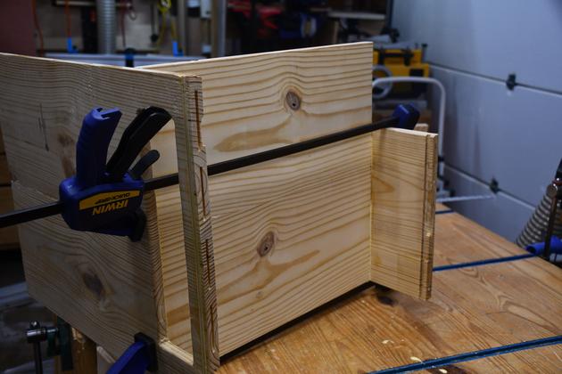
Left cabinet side being glued to bottom and shelf #3.
Again, note the blade's air hole on the right of the bottom.
|
|
Bottom, BH #2, shelf #3.
|
|
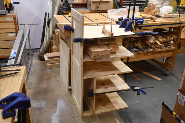
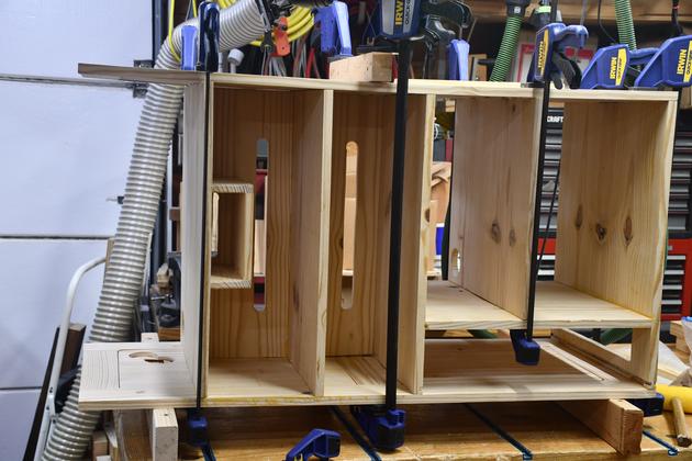
Bottim right side, shelf 4 and shelf 2 being glued in.
|
|
More of a side view of shelf4 and 2 being glued.
|
|
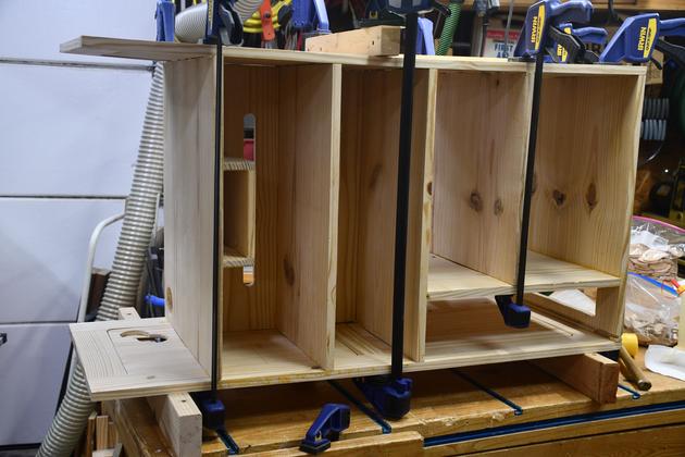
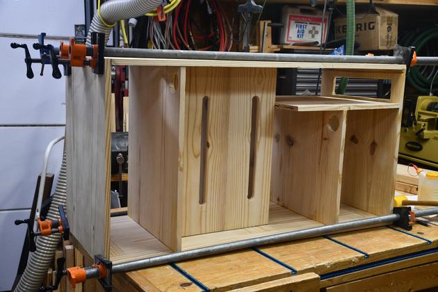
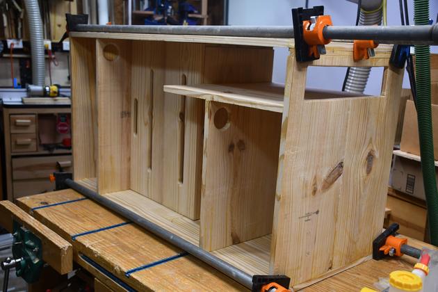
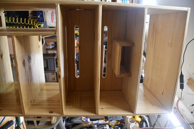
Top right view of shelf 2 and 5 port shelf being glued.
Also note the cable slots in BH-1, for the switches.
|
|
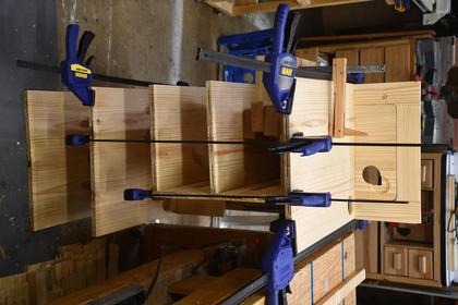
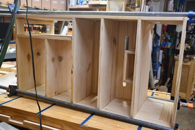
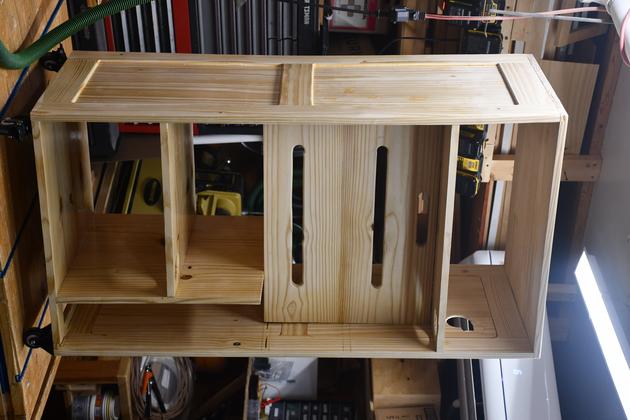
Shelf 1 being glued.
Note
the cabinet is actually in it's proper orientation,
vertical that is.

Nuther note,
the cabinet's top leaning against the end of
the workbench on the far side of the cabinet.
|
|
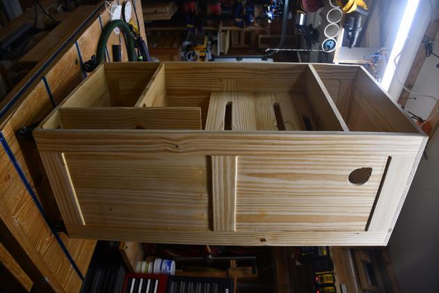
View from cabinet's right side.
|
|
Laying on it's left side, right side being glued on.
|
|
Right side glue on, from the cabinet's bottom.
|
|
Note
The cable slots on shelf 3, 4, and the 5 port.
|
|
Top being glued. Viewed from the cabinet's top rear.
There are 5 #20 biscuits on each side.
I had to assemble the 5' pipe clamps, hadn't used
them in a long time.
|
|
Top glue, viewed from front.
|
|
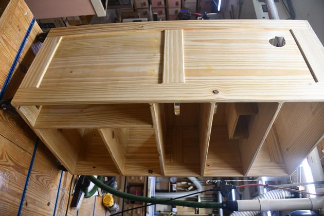
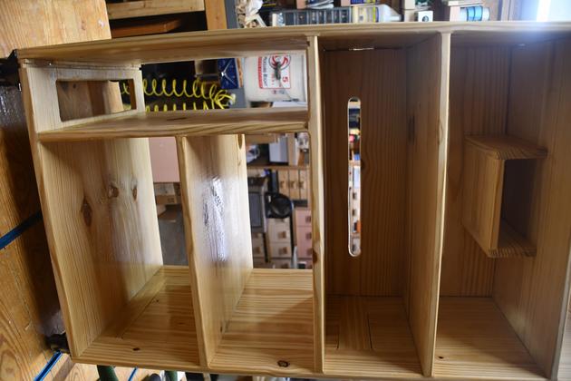
From bottom rear.
You get a good look at the cable routing holes, shelves 2 and
,4 and cable slots in shelves 2 and 3.
All that remains is sanding, rounding over and paint.
|
|
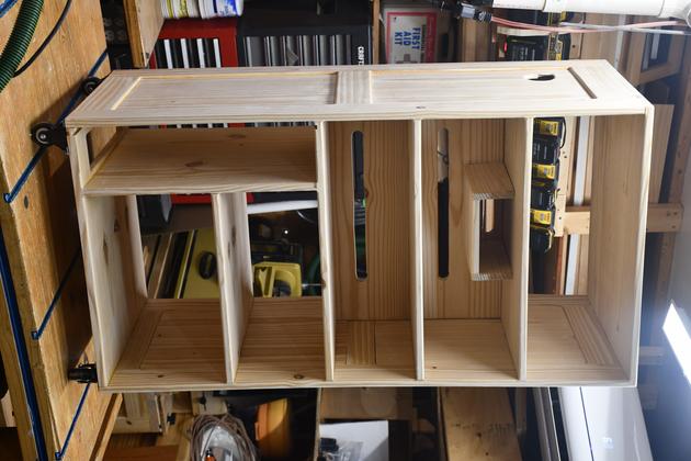
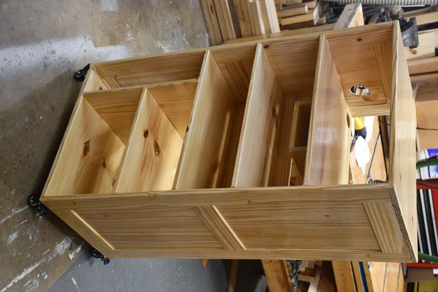
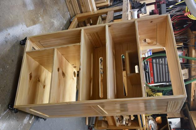
Sanded and ready to paint.
|
|
Closer look.
|
|
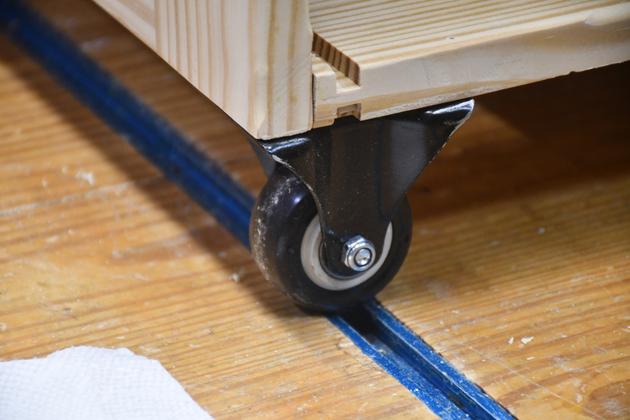
Also has it's wheels, one end is fixed.
|
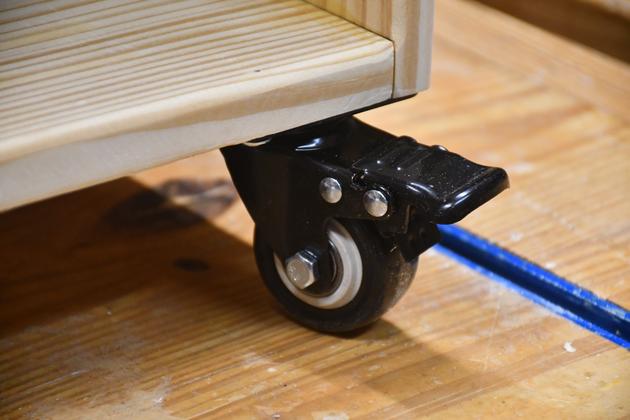
|
The other is swivel.
|
Finish Sand and Paint
|
Rear view.
Sanded and one coat of paint on the bottom half.
I'm getting a little older so I put it on the bench, to paint the lower half.
When this is done, I'll put it on the floor and paint the upper half.
|
|
Left side view.
Note the cable hole upper left.
|
|
Left side an front.
Again, 1 coat of paint on the botom half.
|
|
Upper half front.
|
|
Lower half front.
You can see a little bit of sheen on shelf 4.
|
|
Last coat of paint. I am using clear water based polyurethane.
|
|
A little closer look. from the left front quarter.
|
|
Cabinet rear.
|
|
Right rear quarter.
|
|
From left side.
|
|
Front.
|
|
Close look at the "Blade" area.
|
Clamp Bar
|
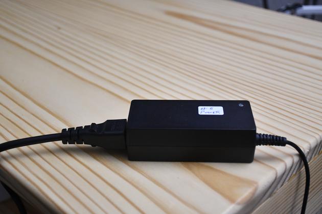
5 of the devices on the network cabinet have in-line power
supplies, similar to this.
They don't have any way to mount them, and after looking
at them, none had any cooling or vent holes, so I came up
with little wooden clamp bars to secure them.

BTW, I'm doing the same thing for the KVM.
|
|
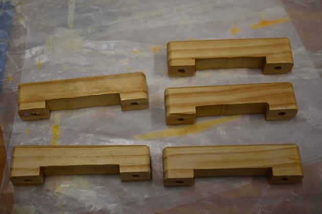
Here are the little clamp bars for the in-line power supplies.
Side view.
|
|
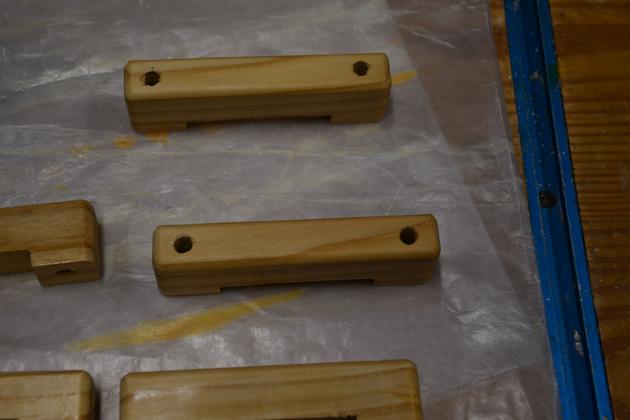
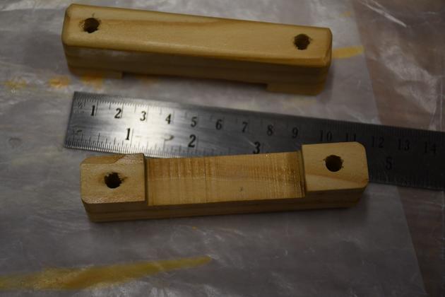
Top view, showing 1/4" holes for the 6mm hanger bolts.
|
|
They are 4" long.
|
|
I sawed out the notch with a 10" bandsaw.
|
Install
Cabinet Front
|
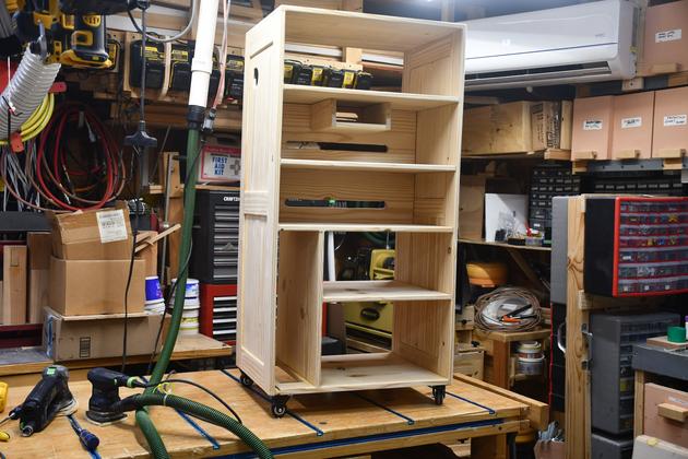
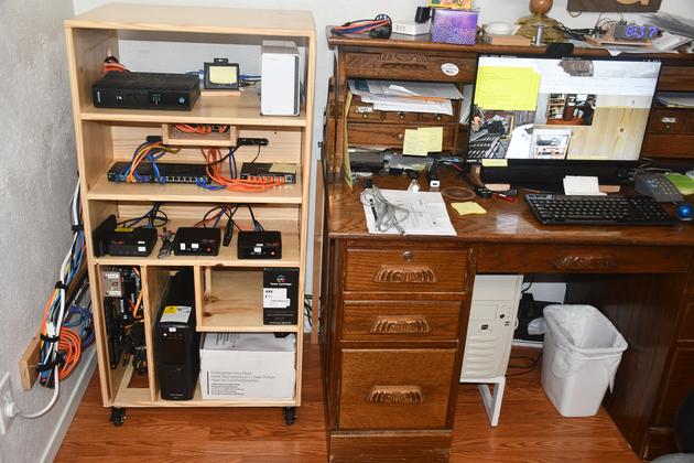
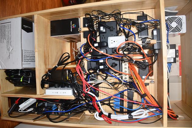
Here is the new network cabinet in my office.
|
|
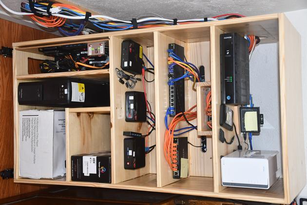
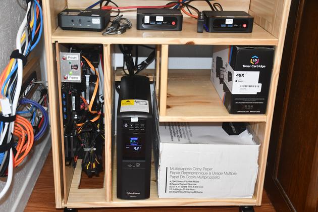
Closer look at the cabinet front.
Note the UPS, on the bottom shelf, just to the left of
 the paper box.
|
|
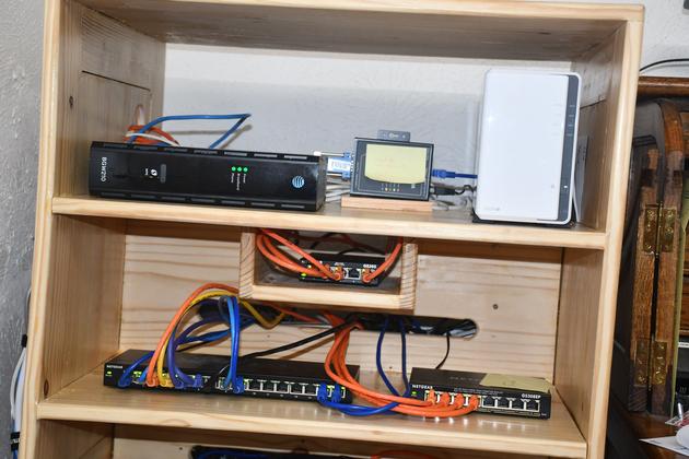
Shelf #1, the ATT internet modem, the interface to the
weather station, and the NAS.
You can also see the mini-shelf (below shelf #1) holding
the 5 port 1Gb switch that connects (and isolates) the
CCTV system to the main network.

Shelf #2 has the switches, 16 port 1Gb left, 8 port 1Gb POE
on the right (part of the CCTV system)
I know the 16 port switch doesn't look very full.
|
|
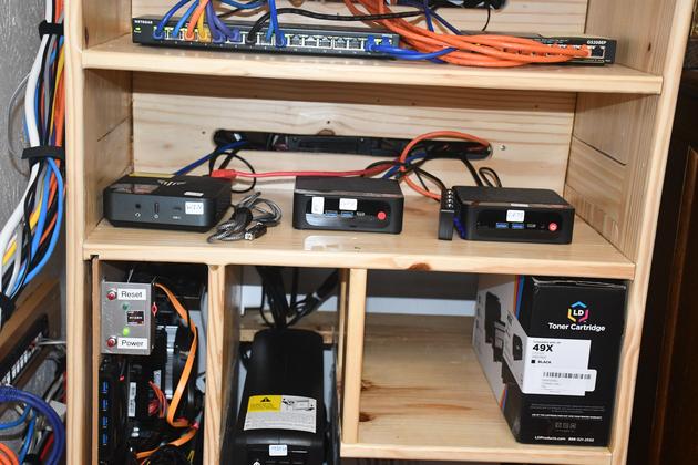
Bit of overlap: shelf #2, shelf #3, and top of shelf #4.
|
|
Shelf #3, #4, and bottom.
Note the 3 minipcs on shelf #3 (Win, backup Gwy, and Cams).
Vertical slot on the left holds the Gateway computer.
Just to the right of the Gateway, is the UPS, you'll note
the vetical support holding shelf #4 in the center.
On the right is laser toner (shelf #4) and printer paper
(bottom).
|
|
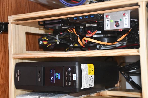
Close look at the Gateway and the UPS.  Note the cyberPower
is indicating 72 min. as remaining run time.
|
Rear View
|
Rear view of the network cabinet.  You can see the 12 slot plug strip (black)
center left.
|
|
Closer Rear view, just below shelf #1.  You can see the black
12-hole plug strip center left.
|
|
Lower back of the UPS.
|
|
Main plug strip, on the right, just above and behind the UPS.
|
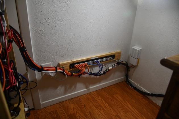
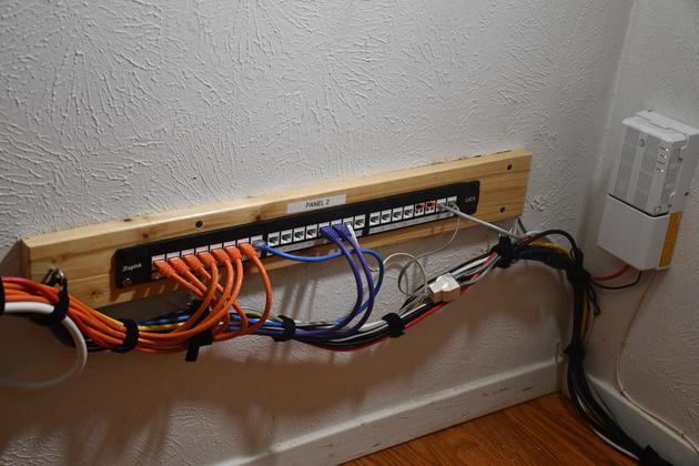
Panel 2
|
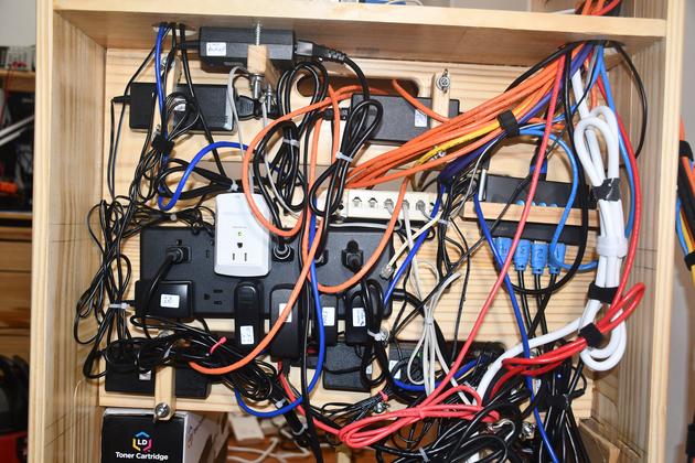
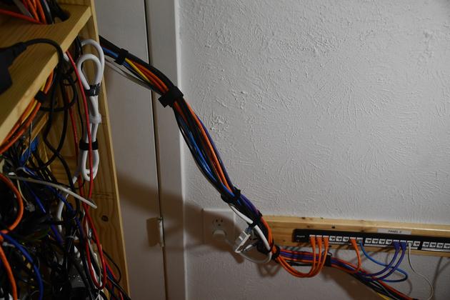
Panel 2 with all cables velcro'ed and routed around the corner.
|
|
Closer look at panel 2.  I used Velcro instead of spot ties,
because it lets me make changes easier.  BTW: The little
white box on the right wall, is the ATT fiber modem. The
cables on the floor leading right, go to my workstation,
the monitor, keyboard, and mouse.
|
|
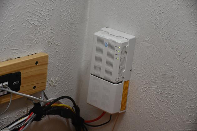
Close look at the AT&T fiber modem. I replaced it's power adapter
with a longer cable, so I could roll the cabinet out from the wall.
|
Cable Management
|
|
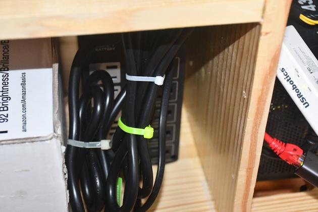
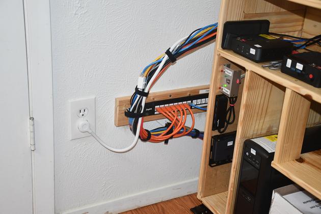
Cabinet front, note all the cables on the left.
They come through a hole, above shelf #1, on the left side
of the cabinet, behind the ATT modem.
You can see the flex point on the lower left.
Aslo note the Velcro Strips holding the cables into a bundle.
I buy Velcro Rolls from Amazon.com.
|
|
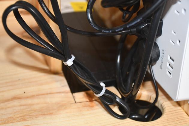
With the cabinet rolled back against the wall.
Note how all the cables flex around and don't interfear
with the cabinet as it is moved in or out.
|
|
With the cabinet rolled out you can see how the cable
flexes but doesn't get in the way.
|
