|
Construction of Mobile Loading Bench |
|
|
Construction of Mobile Loading Bench |
I recently built another one of these for Betty's grandson Kyle. It has a few new innovations and, in some cases, more details on construction. Here is a link to Kyle's Loading Bench.
|
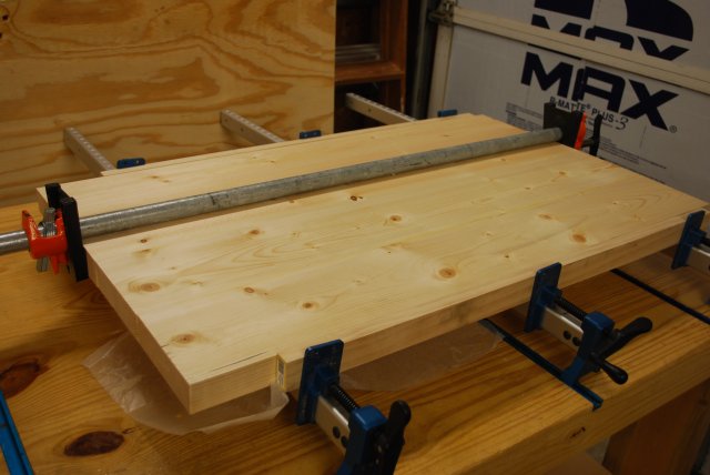
Top Edge Joining
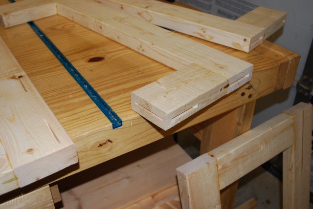
The top is made of 2x6 white pine, edge joining using #20 biscuits.
|
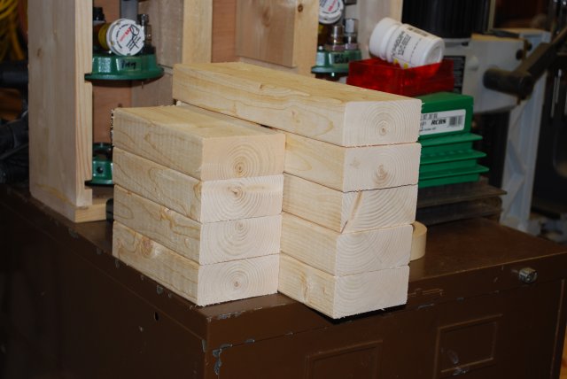
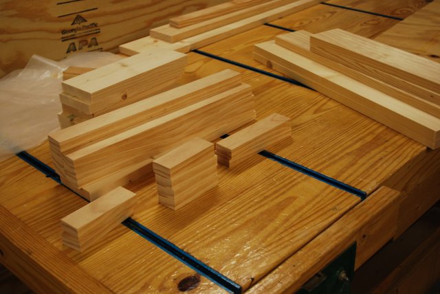
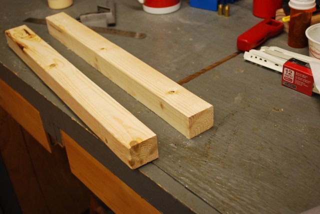
| Frame cross pieces. The long pieces are for the top and bottom of the Left, Center, and right end of the Bottom frame stringers. The short pieces go at the top and bottom of the Right Front and Rear frame members. |
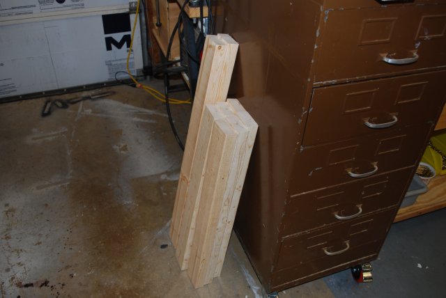
| Frame vertical pieces and long pieces are the bottom stringers. |
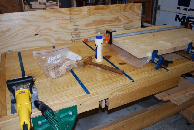
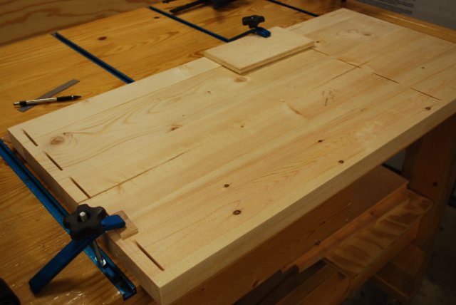
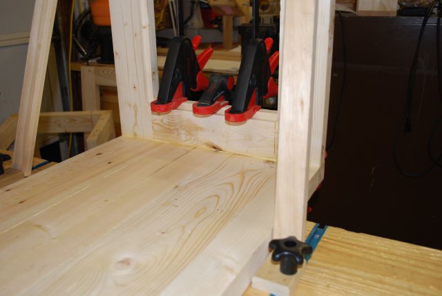
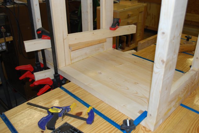
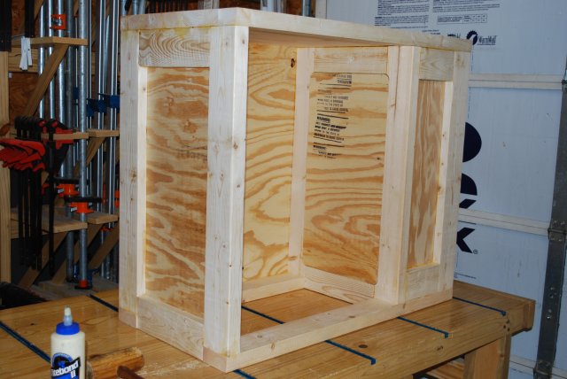
| The Wood Working bench with the loading bench top joining. This is where I build most projects because its very flat and makes it easy to keep frame pieces in a single plane. Note the sheet of 1/2" plywood for the panels in the background. |
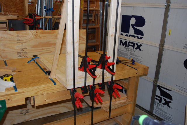
| The left vertical frame in the glue clamps. You will notice the bottom frame stringers also in glue clamps in the left rear. The wooden mallet is for makig minor alignment adjustments. Look here for diagrams. |
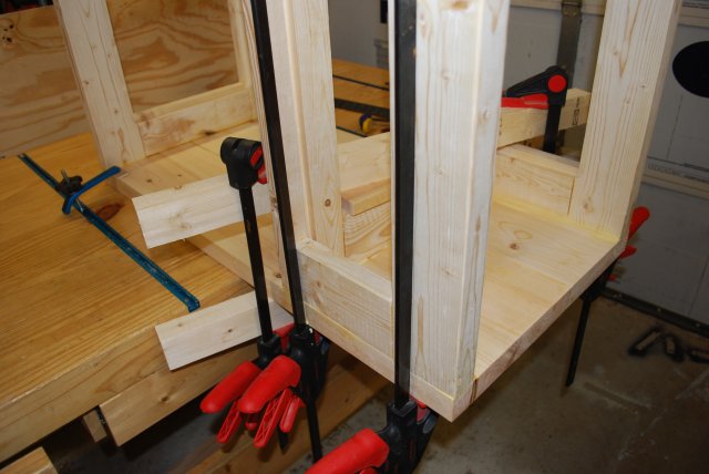
| The right end of the bottom frame stringers in glue clamps. The frame stringers only have a cross piece at the right end (open end of the loading bay) since the stringers are notched into the center and left end vertical frame piece. Here is an example of how these are joined. |
| Top ready for 1st sanding and sloting. |
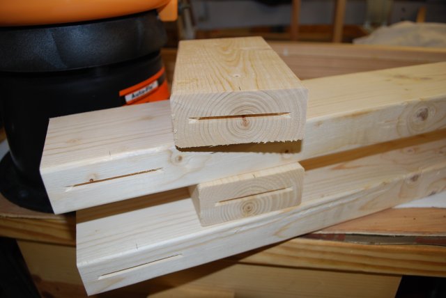
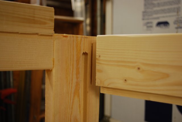
| Right frame member biscuit slots. |
| Center frame member biscuit slots. This is the bottom of the center member where the cross piece extends below the end of the verticals to contact the bottom stringers. |
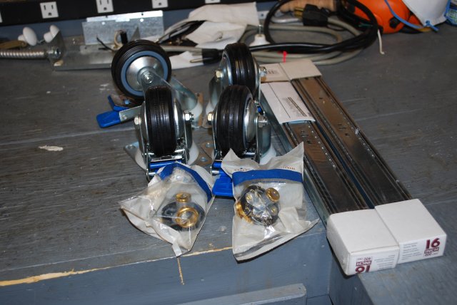
| Casters, locks, and drawer slides. All the metal parts except the tee track. |
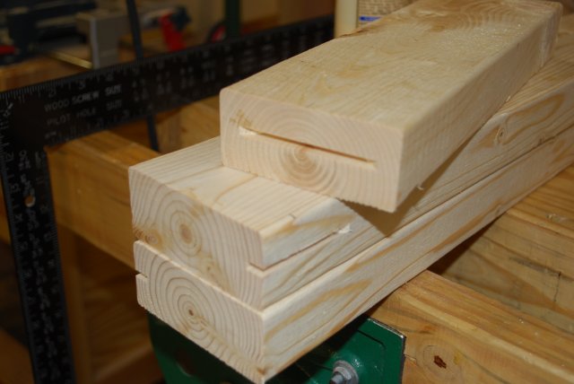
| Bottom frame stringers biscuit slots to hold the center and right frame members. Look here for diagrams. |
| Right end frame member biscuit slots. On the left you can see the bottom frame stringer and it's matching biscuit slots. Look here for diagrams/dimensions. |
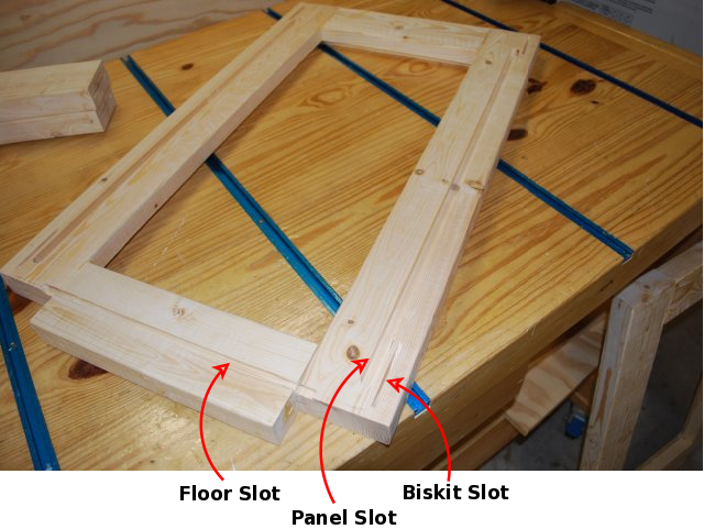
| The center frame member's panel grooves. The outside biscuit slots are for the right end members. Look here for slot diagrams. |
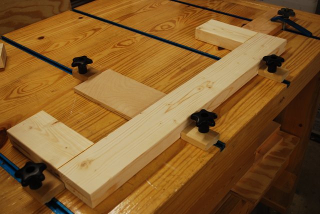
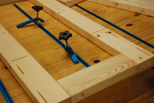
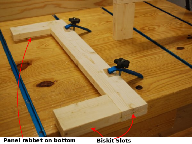
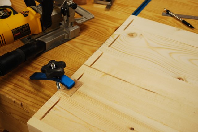
| Right front clamped and ready to cut panel rabbet. Look here for dimensions. Notice how I use tee tracks to help clamp pieces while I work on them on the woodworking bench. |
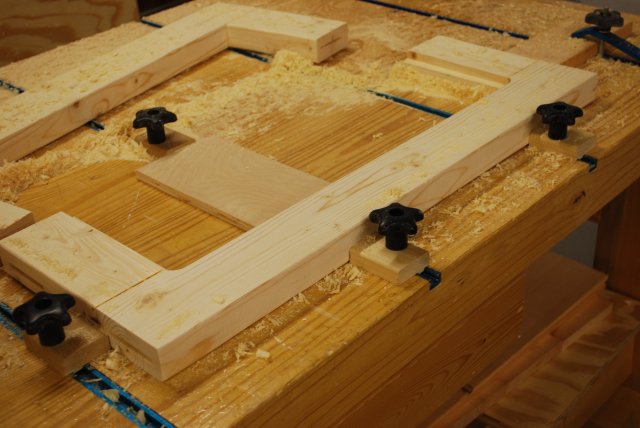
| Right front after panel rabbets are cut. You can see the right rear in the background. Look here for slot diagrams. |

| Close up of right front panel rabbet. The panel is 1/2" plywood so the rabbets are 1/2" X 1/2" with rounded corners. |
| Right front clamped after cutting biscuit slots. |
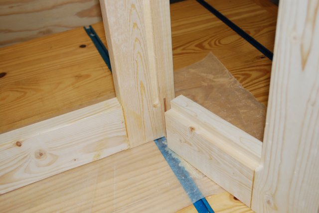
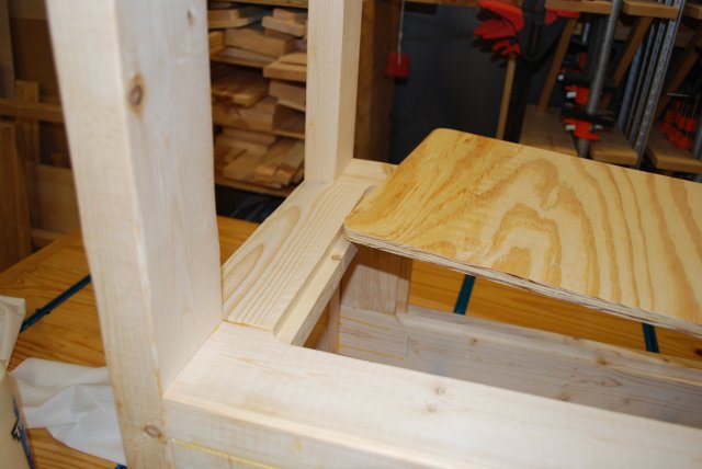
| Center top (its upside down) about to be glued to right end. You can see how the panel slot in the center vertical lines up with the rabbet in the front vertical. Look here for slot and rabbet diagrams. |
| Center bottom about to be glued to right end (viewed upside down). You can see how the panel slot and rabbet will line up. Look here for slot and rabbet diagrams. The small (ragged) slot on the center (to the left) are for the 1/4" floor of the loading bay which is composed of the center and right frame members. |
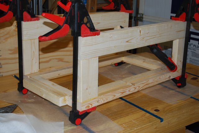
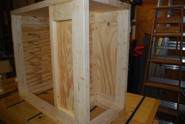
| Center and right assembly in the glue clamps. This will be the frame around loading bay, it also supports the stress of the press which will be mounted in a tee track just above. |
| Slots in top, where frame pieces will join. The top has been trimmed and jointed here to it's final dimensions (18" X 36". |
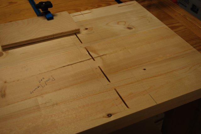
| Top biscuit slots for loading bay. |
| Top biscuit slots for left end. |
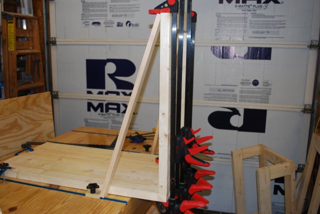
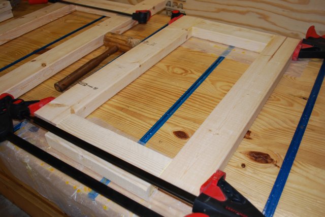
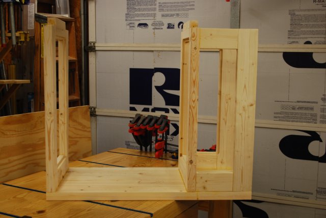
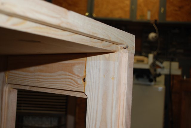
| Left end glued to Top. The diagonals are holding it square while the glue sets. Note the right end frame on the lower right. Here is a later example of how I do this. |
| Left end glued to Top. |
| Left end glued to Top. |
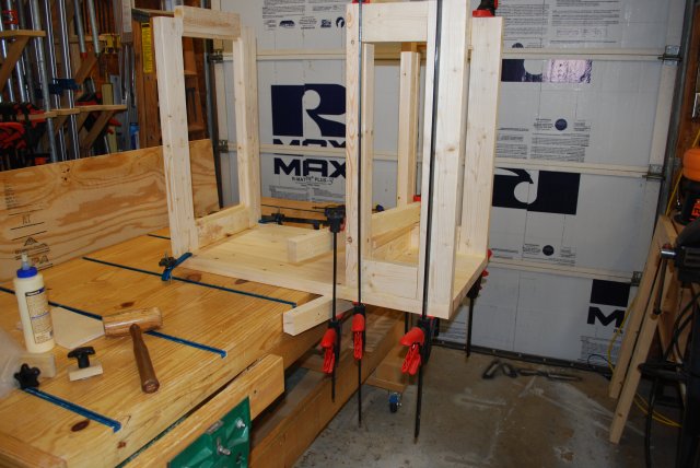
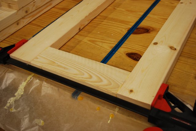
| Loading bay frame (center + right end) glued to Top1. There is about 1500# pressure (six large bar clamps) on it now. These large bar clamps, are good for about 250# each, pipe clamps produce about 500# pressure. You'll notice another loading bench in the background, I built this one for someone else. |
| Loading bay frame (center + right end) glued to Top2. |
| Loading bay frame (center + right end) glued to Top3. |
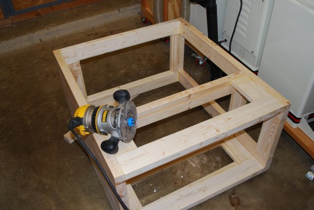
| Glued frame with no stringers yet. |
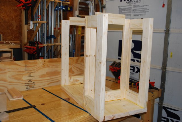
| Glued frame from loading bay end. |
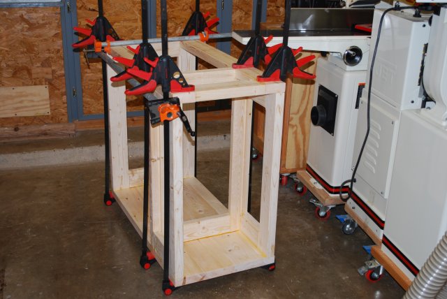
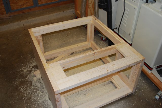
| Bottom stringers being glued on. |
| Parts for press rack. Drawer parts are on the right. |
| Frame back ready to rabbet. |
| Frame back rabbeted for rear panel. |
| Center frame member ready to have it's panel glued in. I glue these panels just like I do drawer bottoms, put down the glue bead, place panel in position, the use 1" wire nails to hold a little pressure till the glue sets. Clamping is a little more difficult at this point, so I use the small nails. |
| All panels glued in. |
| Panels glued into loading bay. |
| Drawer handles ripped. |
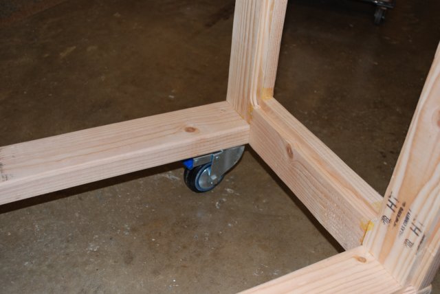
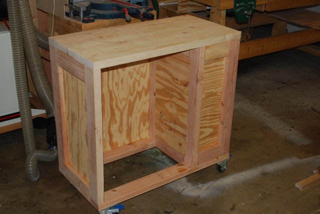
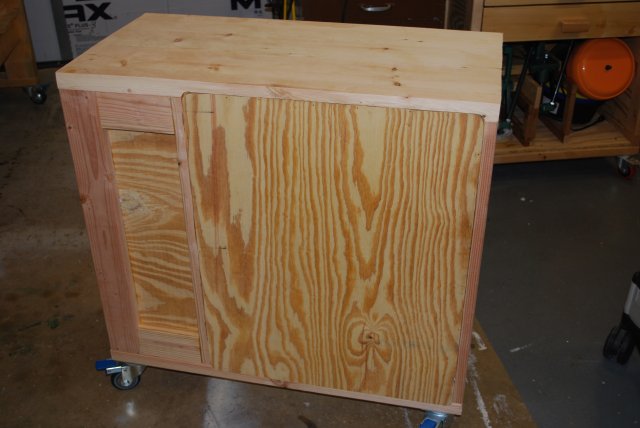
| Right rear quarter view of bench top, frame, and casters before adding the plywood panels. Remember, the glued-in panels are an integral part of the frame and give it much of it's stength. This sequence of frame pics is from the first loading bench I built (my own). |
| Frame lower view from rear showing rabbets for rear panel and left side panel. |

| The lower frame from the right end showing the partition frame and rear panel rabbet. |
| Rear view of top and rear panel rabbet. Also left panel rabbet. |
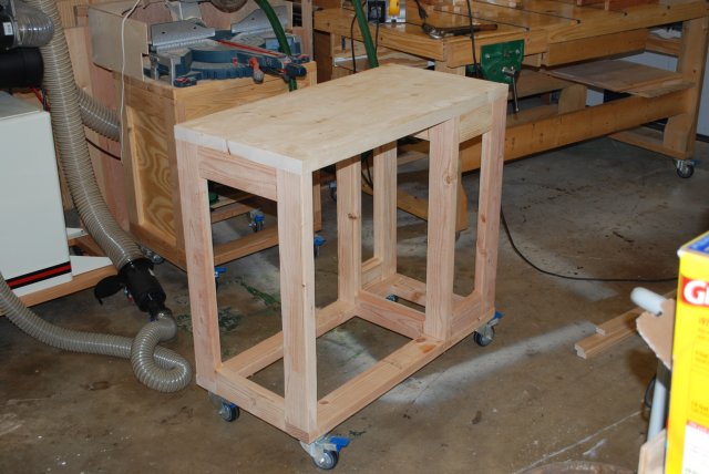
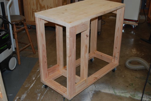
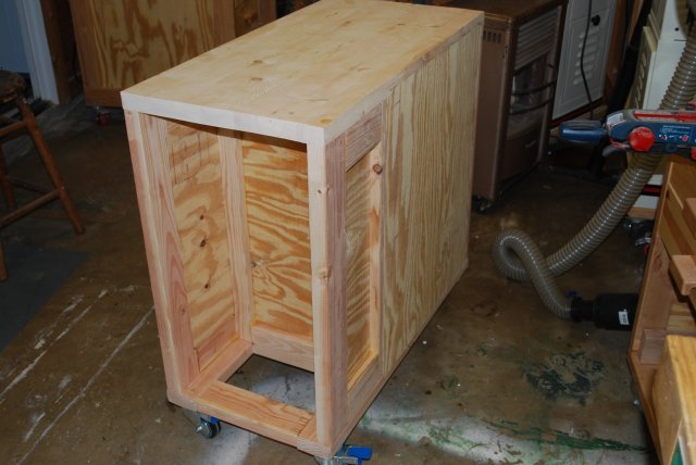
| Front left quarter view of entire frame with casters. |
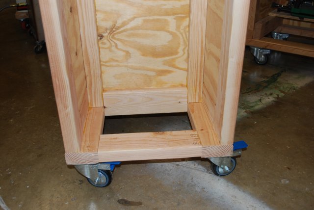
| With panels, right end bottom view. The floor of the loading bay will be added later, before painting. |
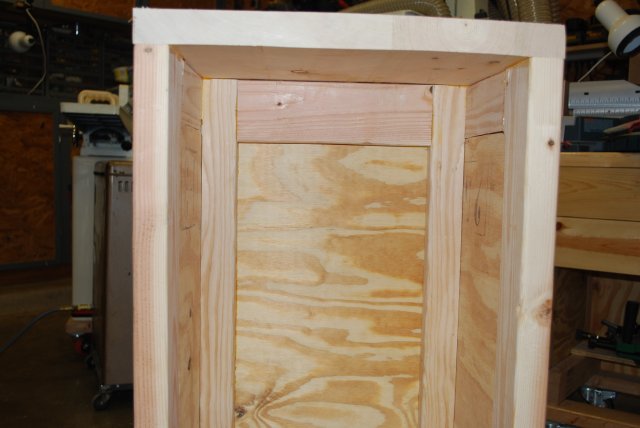
| With panels right end top view. |
| With panels left front view. |
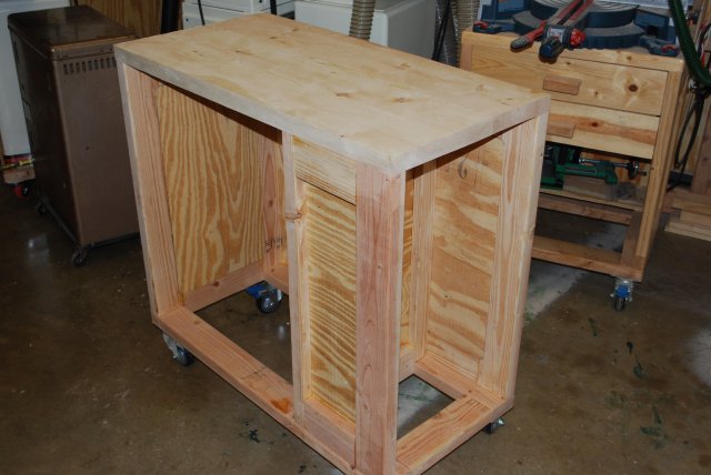
| With panels, front right view. |
| With panels left rear view. |
|
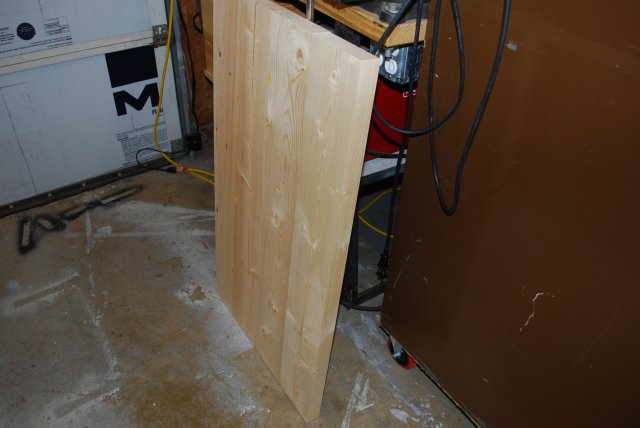
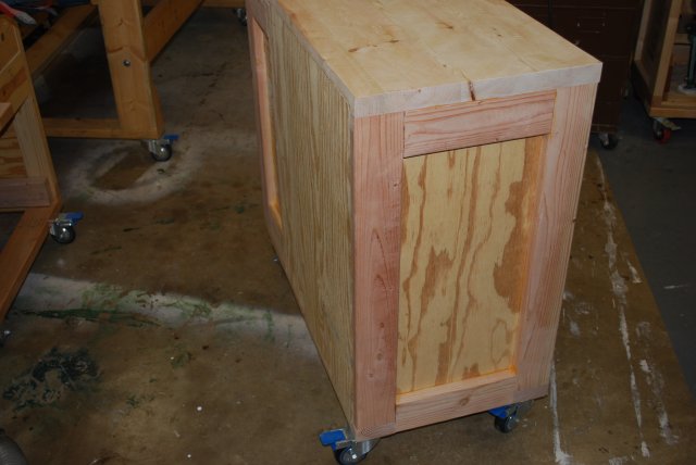
With panels rear view.
Note rear panel is flush with outside while all other panels are flush with inside. This makes for better drawer slide mounting amd gives something to hold onto while moving the finished bench around. |
| With panels right rear view. |
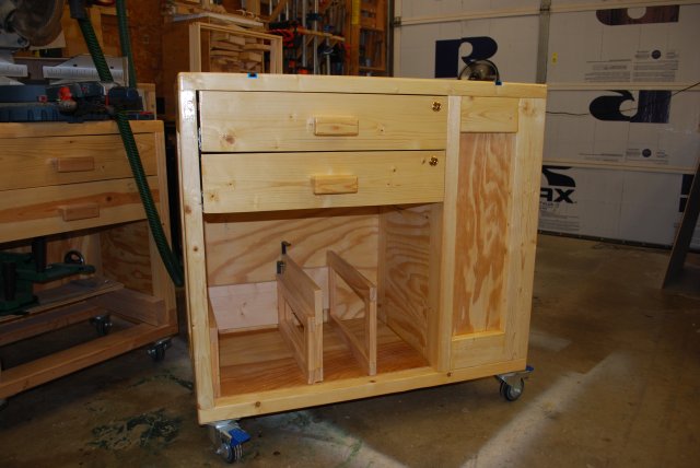
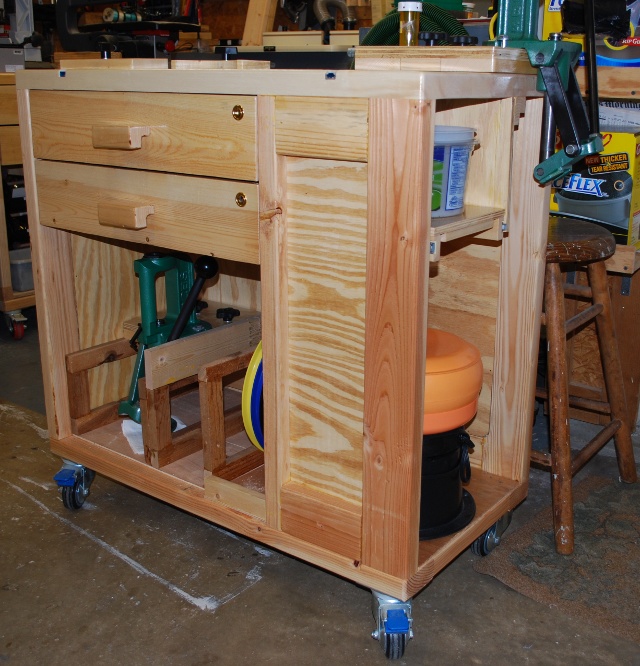
| Finished, all it needs is a press and it'll be ready to start loading. Here is a link to my page on making drawers and handles. Notice the two clips to hold the press bases on the press storage rack. |
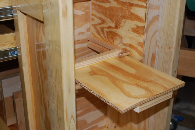
| Finished loading bay. You can see the guides for the loading shelf and I glued in a floor. You can also see the floor glued into the main bay on the left. |
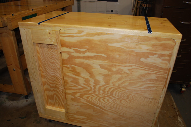
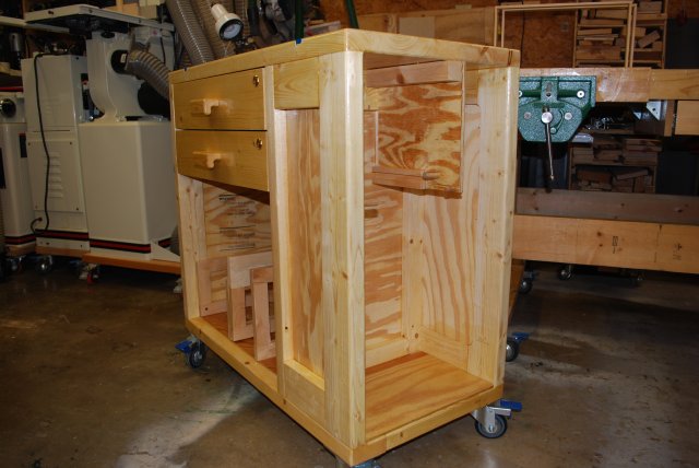
| Back of the finished loading bench, note the panel is flush with the back, its easier to do, provides the same strength, and allows more depth for the drawers. Also note the back loading bay panel is inset so the inside of the loading bay is flat for guides etc. |
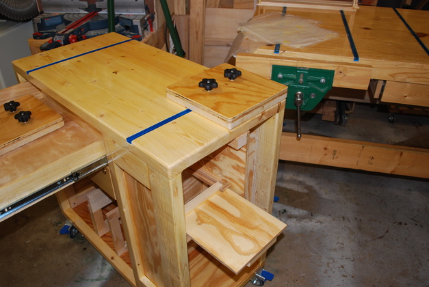
| With a press base in place. You can also see the loading shelf and another base in the top drawer. |
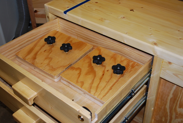
| The top drawer with the two bases. Note these are full extension drawers. |
| The finished loading bay with the loading shelf extended. You can see the pull handle glued to the bottom front and stop block glued to the top back of the loading shelf, |