|
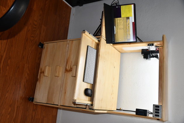
Keyboard extended | 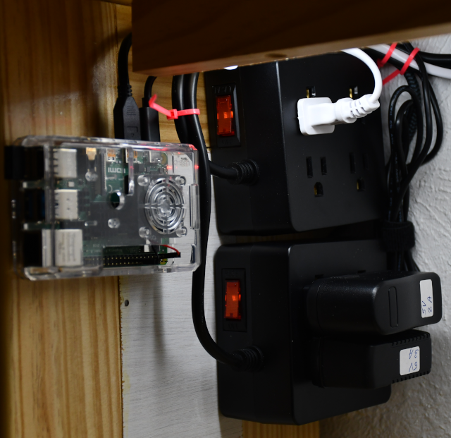
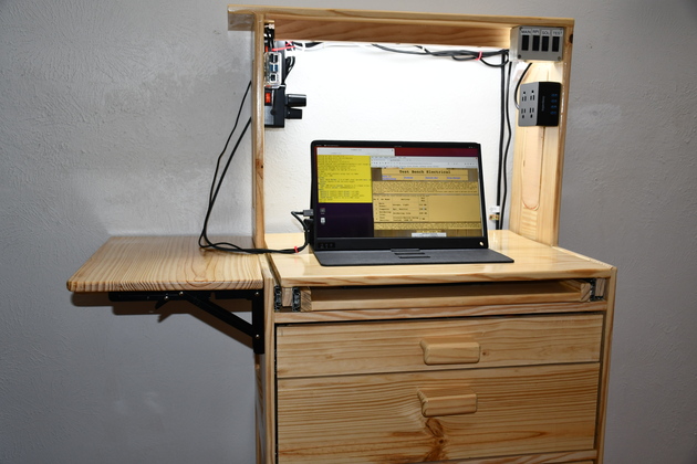
Rpi-4, main and computer plugstrips | ||
|
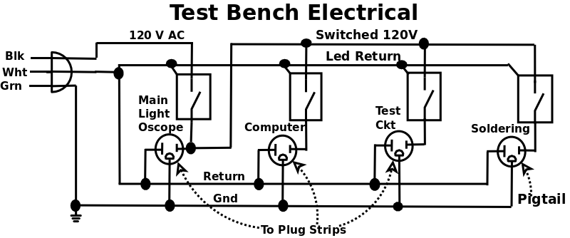
Test Bench Electrical
| ||||
|
Keyboard extended |
Rpi-4, main and computer plugstrips | ||
|
Test Bench Electrical
| ||||
| Back to Woodworking | Diagram | Switch Box | Plug Strips |
The Electronics Test Bench will have a very low 102 Volt AC power requirement.
For instance, the computer (rpi-4 and monitor) requires abot 25 Watts or about 208 MA, the light requires 10 Watts or 83 MA, the Hantek DSO5102P scope requires 30 Watts or 250 MA.
I don't do much heavy soldering (large wires, connectors, etc.), the 80 Watt Iron 600 MA, my Antex 15 Watt iron (the one I use most of the time) draws 125 MA.
If I'm testing a ckt with 3 Nanos each draws about 19 MA @ 5 Volts (.095 Watts) for a total of .285 watts, or 2 Ma of 120 Volt AC.
An 80 Watt soldering iron requires as much power as all the remaining power consumption.
Peak circuit power requirement (with 80 Watt Iron on) is abou 1.2 Amps or about 144 Watts.
I'll probably not run the soldering iron while the test ckt is running
The following table does not include power supply losses since they are all switching (electronic) power supplies (need to add about 20% for power supply overhead).
I decided I needed four 120Volt switched electrical circuits for my test bench.
| Sw # | Sw Name | Devices | Tot Pwr |
|---|---|---|---|
| 1 | Main Power: | Oscope, light | 333 MA |
| 2 | Computer | Rpi, Monitor | 208 MA |
| 3 | Soldering Iron: | Soldering Iron | 600 MA |
| 4 | Test Devices: | Circuit/device being tested, +USB 5V | 7 MA |
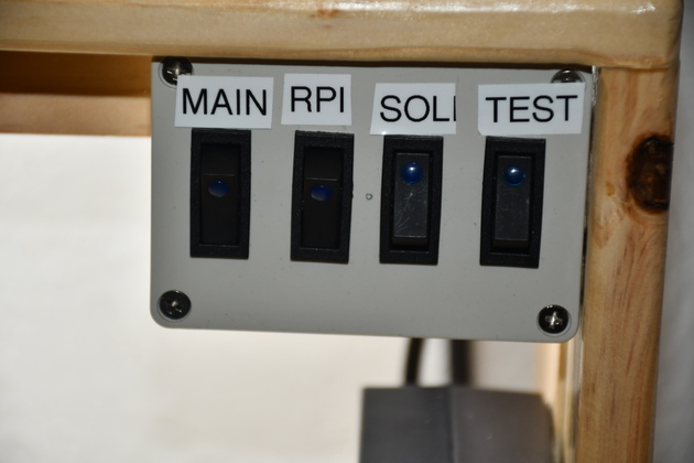
Main power switch will control lights, oscilloscope and feed the other circuits. Computer would control Raspberry pi, monitor (kbd & mouse batt pwr). Soldering Iron power switch would control just the soldering iron. Test Devices switch would be used to switch the test devices power on and off. The Main, Test, and Computer power will have USB-A Plugs. I will have a 3-wire with a male 120V 15A plug power cord to the switch box, and a female pigtail (approx. 2' long) for the soldering iron, and direct connects for the plug strips.
First electrical thing I installed was the LED light bar so I could see how to mount the other stuff inside the hutch. We have these LED strips under all our cabinets, etc. the are about $6.75 each (you have to buy 6 of them) and put out 1000 Lumens.
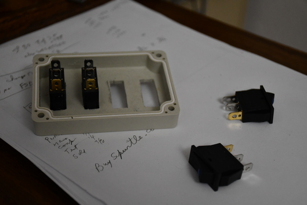
Initially I didn't think I would need to switch the computer (Rpi & monitor) seperately so I built a switch box with only 3 switches. After getting everything running, I realized I wouldn't need the computer a lot, so I built another switch box with 4 rockers. I got a little more substantial rocker switches and a little larger box. I had already purchased the plug strips with 4 USB-A ports and surge protection, so I purchased one more for the computer power.
|
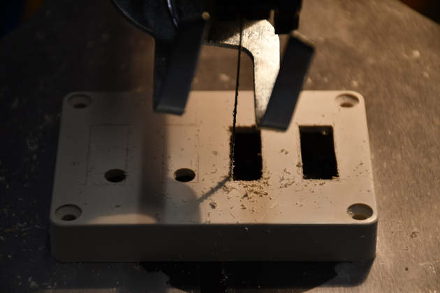
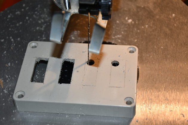
I marked where the rockers would go in the switch box lid, drilled a 3/8" hole in the corner of each switch position, then used my scroll saw to saw out the rocker holes. The previous box used round rocker switches, which I didn't think were quite as durable as these. |
|
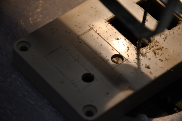
A better look at the 3/8" hole drilled in the corner of each switch position. |
|
Starting the third rocker switch hole. |
|
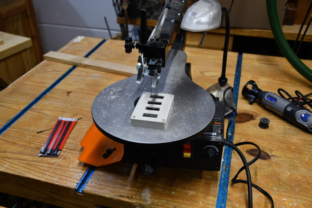
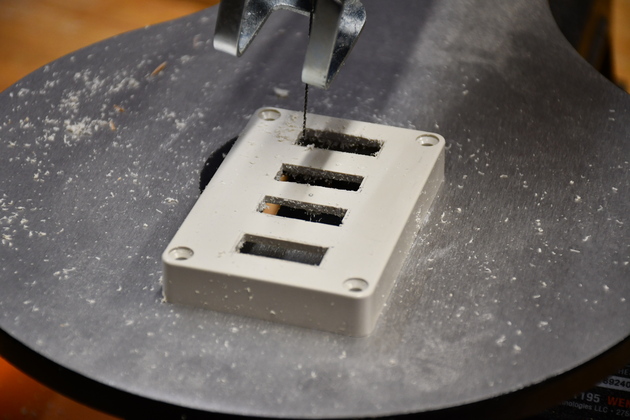
All holes drilled on the scroll saw. |
|
Closer look at sawed rocker switch holes. As usual, they'll need a little smoothing with a file. |
|
Mounting the rocker switches in the switch box lid. |
|
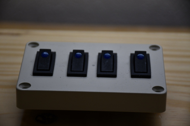
All rocker switches mounted. |
|
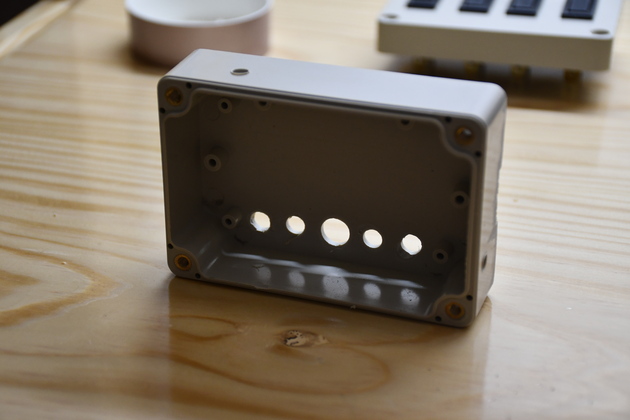
Holes drilled in switch box bottom. Note the small holes in the top and right side, they're for mounting to the cabinet. The holes in a row near the bottom/back of the switch box are the power wire holes for Power-In, to main plug strip, to the soldering iron (large hole), to computer plug strip, and to test device plug strip. This box had mounting tabs on each side that didn't fit into my scheme, so I sawed them off. |
|
Finished and mounted switch box. Apparently, it needs 12 Volts to turn on the LEDs? |
|
All electrical stuff mounted. You can see the switch box (upper right inder the hutch), and below it the plug strip for test devices. The other two plug strips are mounted high on the left at the back behind the rpi. |
|
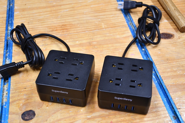
These are two of the plugstrips I bought for the test bench. Note they each have 4 receptacles and 4 USB-A 5 volt power ports. They'll be used for main, computer, and test device power. |
|
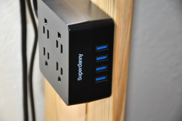
Test power plug strip. |
|
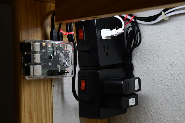
Rpi, main and computer plug strips. |
|
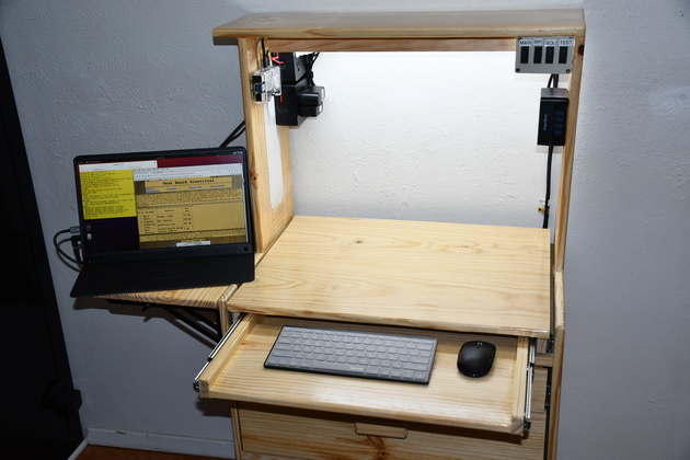
Everything fired up. Note extension raised on the left. |

|
|