|
|
|
Using the JWBS-10os with a 1/8" blade
|
056/01/14: Broken Blade.
03/12/13: Cleaned up.
I purchased a Jet 10" Bandsaw last week (10/30/12) and an Olsen 1/8" blade (the Jet docs say it will work with a 1/8" blade).
I tried to adjust the blade guide bearings for the 1/8" blade and could not make it work, the back blade thrust bearing wouldn't adjust far enough forward (close to the blade's back).
I called Jet and after a couple of false starts, Jet sent me a set of blade guide bearing blocks that worked.
Jet has been very responsive to my calls for help and we finally resolved the problem.
I am showing here how to replace the blade guide blocks on this saw.
The first five pics are with the original blocks, and allow a new saw owner to determine if his blade guide blocks are the old or new type.
One note, I am showing the new milled guide blocks provided by Walter Meier, in the future, they may redesign the blocks and a proper block may not look the same.
Another Note, this is only needed for a 1/8" blade, a 1/4" or larger would probably work fine as is.
My 1/8" blade broke and I discovered that no one (that I can find) stocks 1/8" by 67-1/2" blades.
I ended up ordering one from Timberwolf via Woodcraft.
I ordered a 67-1/2" blade, the order on the Woodcraft site shows a 68" blade, I understang they sell by the inch and I get billed by the rounded up inch, but did Timber Wolf get the right length?
We'll see how this comes out.
Link to Making Resaw Guides.
|
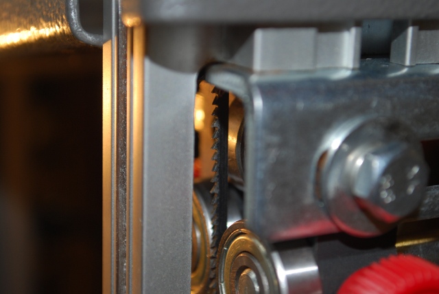
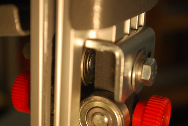
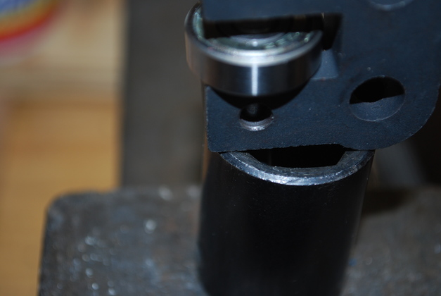
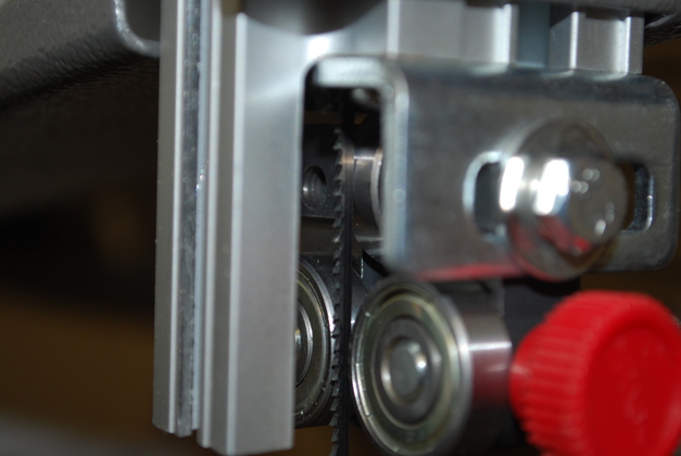
Original guide bearing block:
You can see from this pic, the blade gullets are flush with the front of the side guide bearings and there is a gap between the blade and back thrust bearing with the eccentric in the full forward position.
|
|
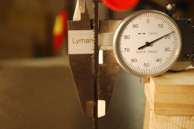
Field guage inserted between the back of the blade and the bearing.
The blade shows no visible deflection when the field guage is inserted and removed.
|
|
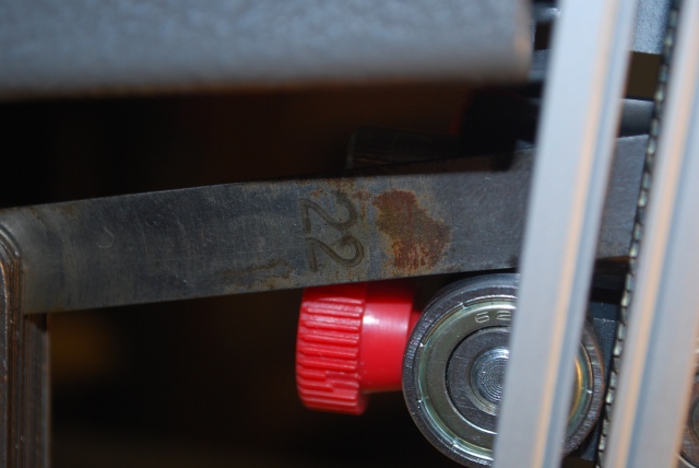
Field guage blade thickness is .022".
Please forgive the rust spots on the guage, its about 50 years old, but you'll note the measuring part is clean.
|
|
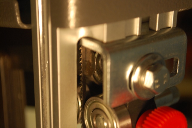
The side bearings are as far back as they'll go, against the block.
|
|
You'll have to take my word that the eccentric for the rear thrust bearing is as far forward as it'll go.
|
|
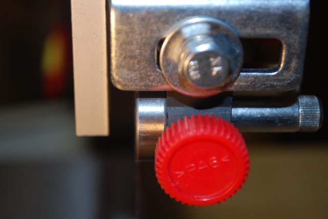
Lower bearing is clear of the blade.
|
|
Blade is tracking not quite dead center, but not wandering.
If I moved the tracking back on the tire, the blade teeth would be touching the side bearings.
|
|
Blade is under tension, I tightened it until the blade stopped wandering.
|
|
The blade width is .118", .007" less than .125", I assume they started out with a 1/8" band and grinding and tooth set ate up the .007"
Or maybe this is the closest metric setting to 1/8"
|
|
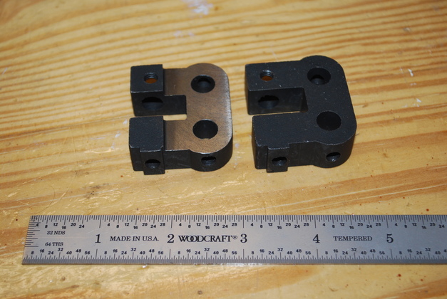
A new milled block on the left and the original on the right.
The upper and lower blade guide blocks are identical.
The one pictured is milled on the wrong side but it does show what the milled block looks like.
|
|
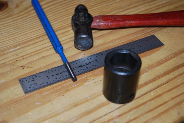
Here are the tools I used to remove the back thrust bearing, the scale is for reference.
A small hammer, a 3/16" drift punch, and a 13/16" socket, for support.
I thought it might be helpful to others to show how to replace the blade guide block.
|
|
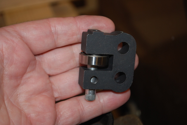
The blade guide with the back thrust bearing.
|
|
Place the socket on something substantial, drive end down (I use my 6" bench vise).
Place the blade guide block on the socket, with the adjuster eccentric shaft down in the socket.
Make sure the blade guide block is supported by the socket, as shown here.
|
|
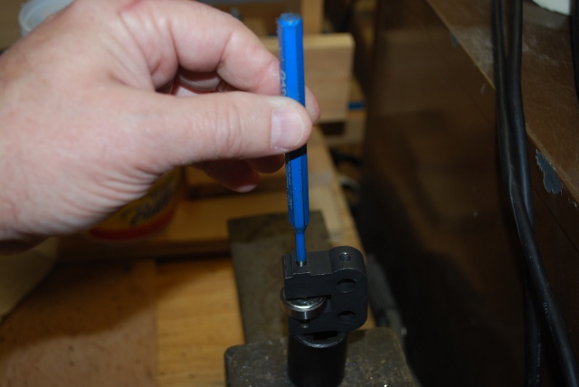
Place the 3/16" drift punch through the 6mm hole and touching the end of the eccentric shaft.
|
|
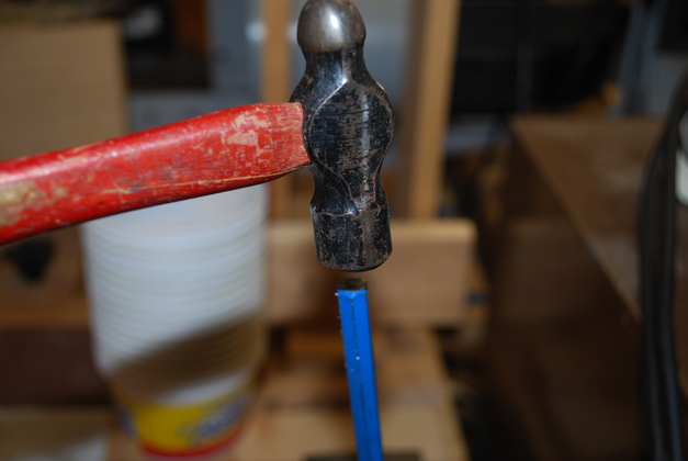
Tap lightly several times on the end of the drift punch, with a small hammer.
|
|
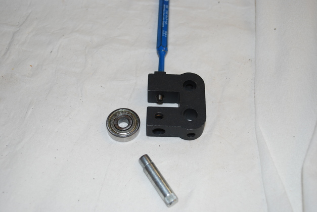
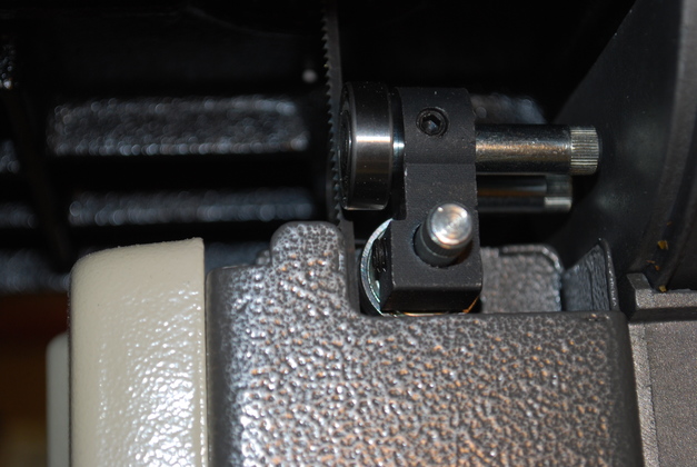
Voila, the eccentric adjuster shaft comes out the bottom after a few taps, you can see the drift punch sticking out of the 6mm mounting hole.
You can see the eccentric rod below the bearing glued block and the bearing to the left side in this pic and the bore for the eccentric rod on the bottom in this pic.
To assemble the new block:
-
Place the bearing block on a solid surface (I use my 6" bench vise) with the larger hole up and the 6mm hole down (reverse of the removal pic).
-
Put the bearing in the slot and insert the eccentric cam into the bore of the guide block.
-
Align the cam with the hole in the center of the bearing,
-
Tap lightly on the end of the eccentric cam rod until the rod is flush with the lower edge of the bearing.
|
|
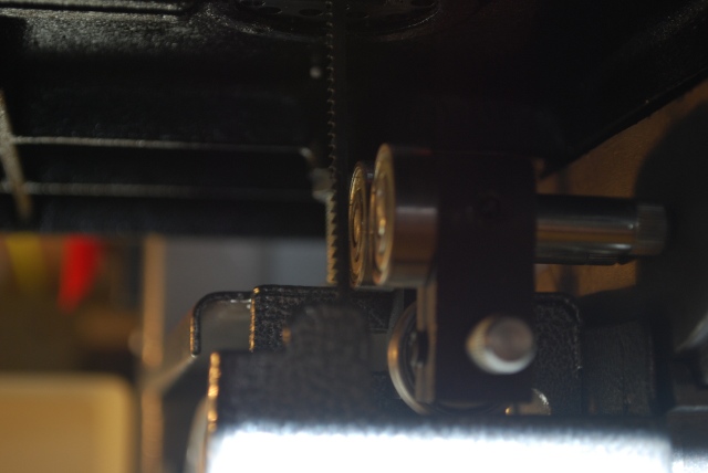
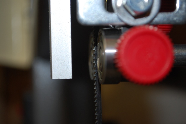
The correctly milled block, you can see the rear thrust bearing adjusts to just behind the blade.
A clearance of about .003" should be a reasonable average, I use a thin piece of paper as a clearance guage.
With the blade tensioned and the bearings adjusted, you should be able to turn the upper wheel, moving the blade but none of the bearings should turn.
|
|
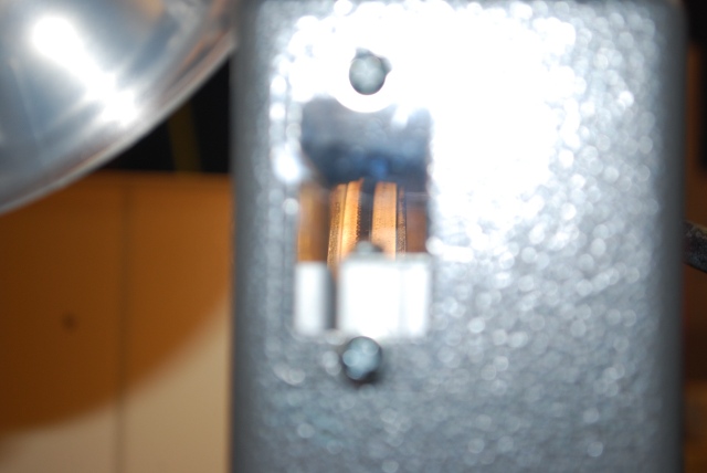
You can see the side bearings are just behind the blade's gullets.
These could actually be moved out toward the blades a few thousandths more.
|
|
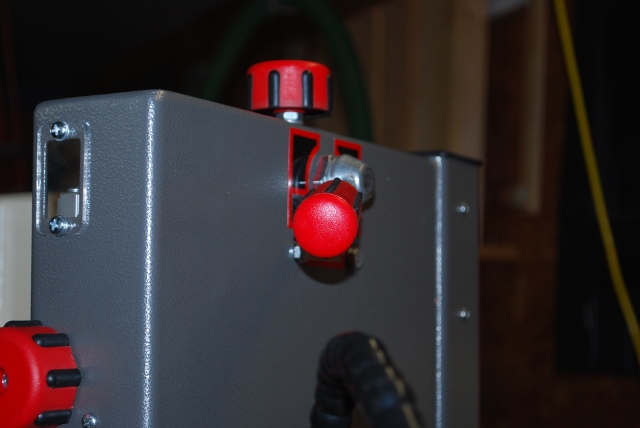
Same adjustment on lower blade guides.
You can see the milled section behind the side bearing.
|