| |
|
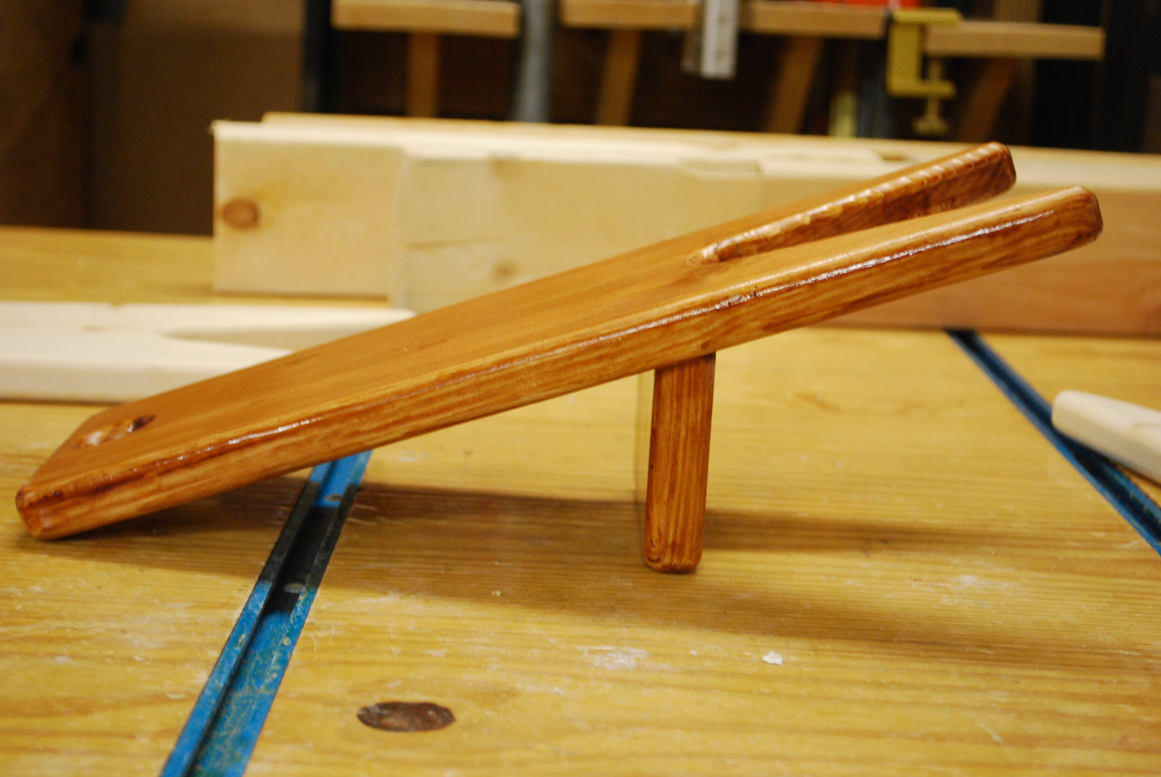
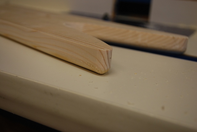
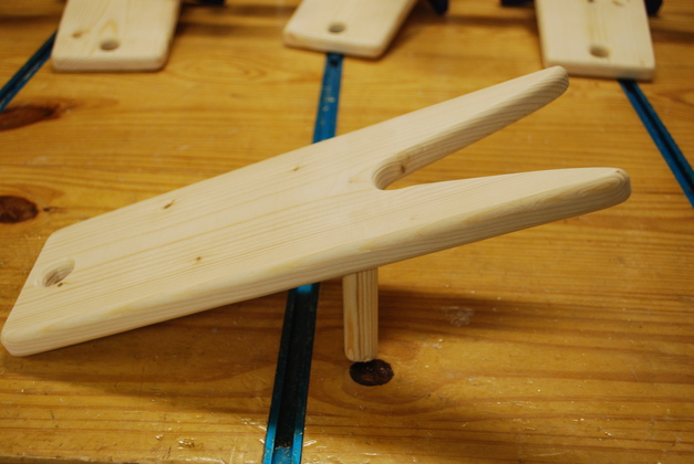
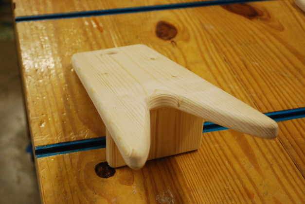
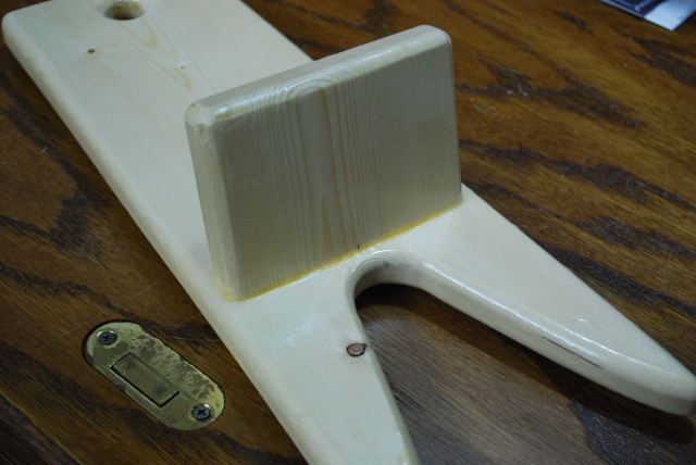
Prototype 2, with beveled
support piece.
| 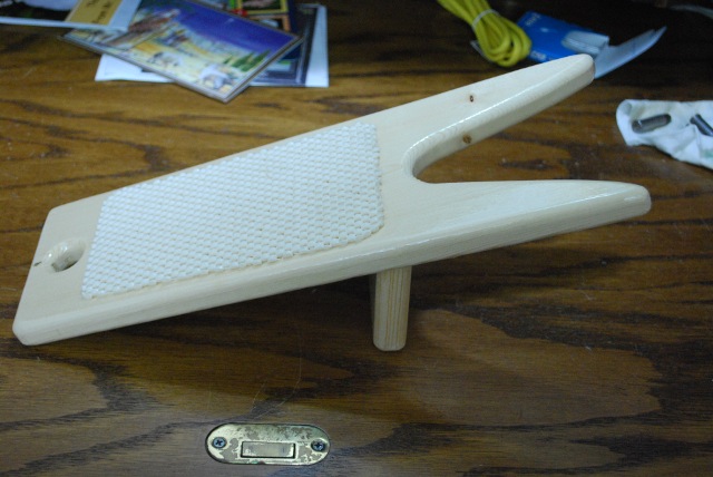
Finished Boot Jack.
|
|
Making A Boot Jack
|
01/06/14: Clean up text fix a dimension error.
12/05/13: Add 2nd top pic, diagram and links to diag & pics.
11/17/13: Page Origin.
The pics on this page came from multiple batches of bootjacks as you will notice.
One batch I colored with a Varathane Poly Plus, which didn't turn out well, so I made a batch with clear poly.
The prototype is also covered with clear poly.
I used a miter saw, bandsaw, 12" disk sander, router table, Plate Joiner (biscuit cutter), and handheld sander to build this project because I have them, but there is no reason why you couldn't do a good job with a jig saw, screws, and sand paper.
You would need to round off the inside of the "heel grabber" (with sandpaper) to protect your boots.
You could even get an inexpensive drum sander that you chuck up in a drill motor to do the rounding.
I looked at using a sticky-backed sandpaper, made for stair treads, for the non-skid surface on top of the main board but it was pricy and nobody locally had any.
So I am going to use the rubbery shelf liner you can get at Walmart or Home Depot and place it directly into a coat of fresh poly.
I have used that to make a non-slip surface on the bottom of other projects and it works great (Please see the Pistol Cocker).

Click for larger Pic
|
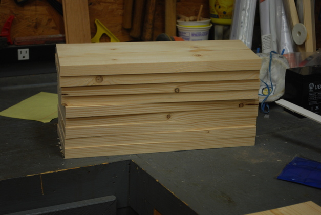
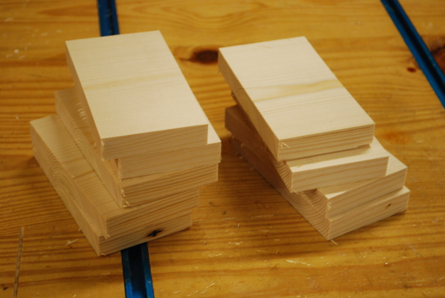
1X6 by 14" long main boards cut out.
|
|
1X6 by 3" supports cut out.
|
|
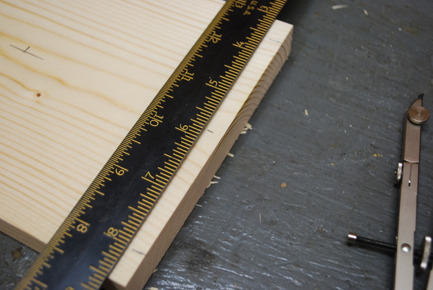
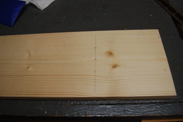
Here I have marked the center line, and the marks 1/2" from top and bottom edge.
I made the same three marks on each end.
|
|
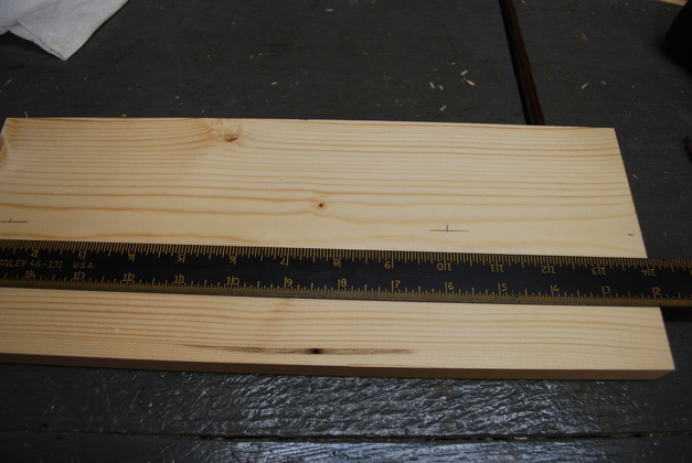
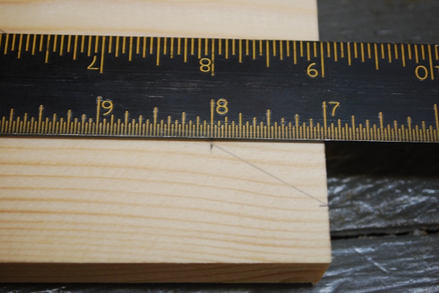
Starting to mark a main board bottom.
You can see the center line, the mark for the center of the 1-1/4" circle and the mark on the left end for the "hanging hole".
|
|
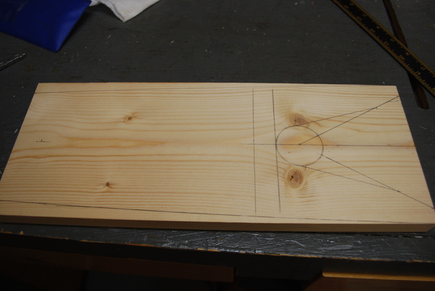
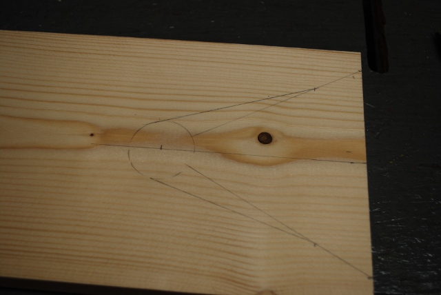
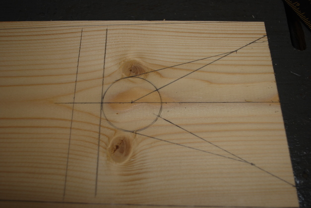
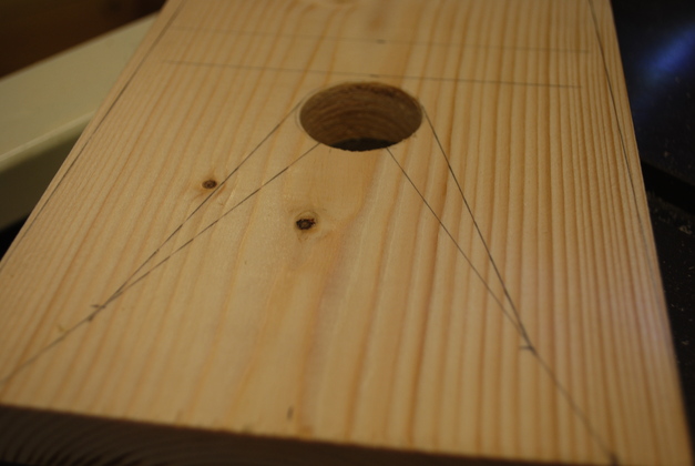
Marking a main board bottom.
You can see the center line,
the 1-1/4" circle drawn,
the marks 1/2" from the top and bottom edge with the straight lines from these to the center, and the intersecting lines from the edge of the circle.
|
|
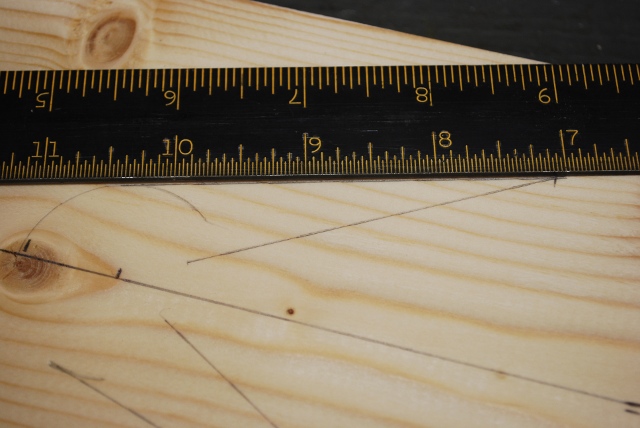
Drawing the intersect point on one of the lines to the center of the circle.
After drawing the lines to the center, come down 1" from the end of the board and mark a point.
|
|
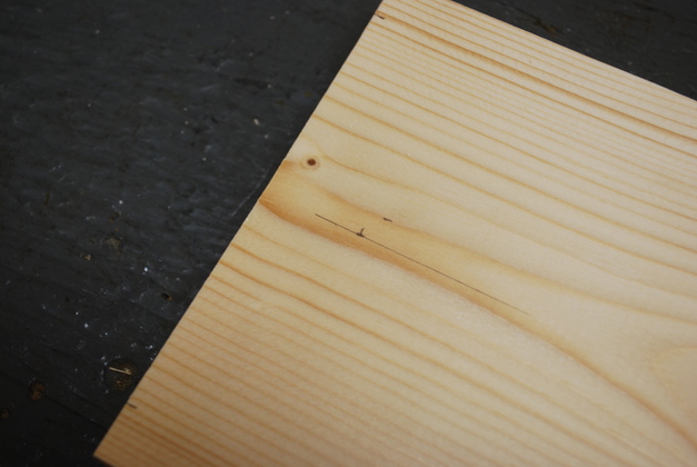
After marking the intersecting point, draw a line from the edge of the circle to the intersecting point.
|
|
Closer look at heel grabber end.
You can see the two transverse lines showing the position of the support baord.
|
|
Left end of the main board's bottom.
You can see the center line and the "hanging hole" marked.
If you look close you can see the marks 1/2" from the top and bottom edge for the "taper lines".
|
|
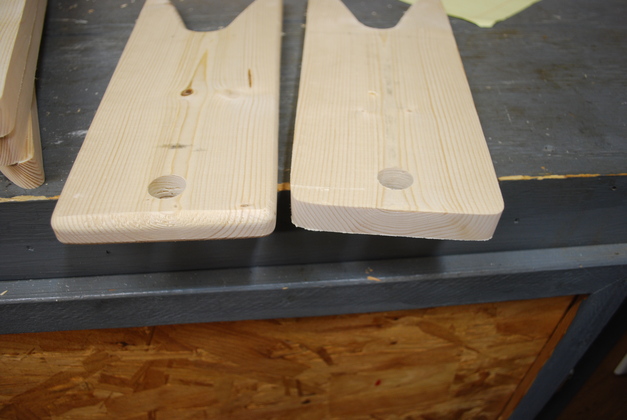
Marks for the support mounting screws on top of the main board.
Even though I didn't screw these bottom supports on, I am showing how to mark for them so folks can do it either way.
|
|
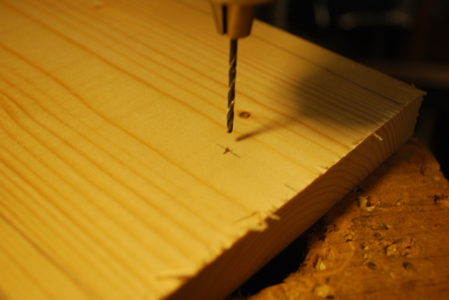
Drilling a pilot hole for one of the "hanging holes".
I used a 1/16" drill for the pilot hole since the point of the forsner bit is just a little larger than 1/16"
|
|
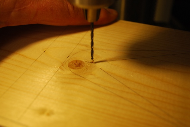
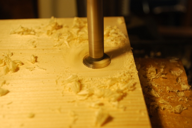
Drilling a pilot hole for the "heel grabber"'s 1-1/4" hole.
A note on board selection, I didn't want any cutouts or hole that had part of a knot, since the knot tends to loosen and fall out later, I selected this board so the knot would be entirely inside the cutout for the "heel grabber".
|
|
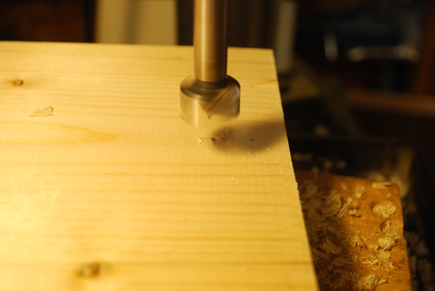
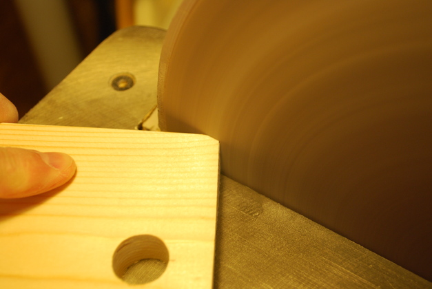
Here I'm lining up the 3/4" forsner bit with the pilot hole for the "hanging hole".
|
|
I drill about half way through the board from the top.
|
|
Then turn it over and drill from the other side, again lining up with the pilot hole.
This makes sure I don't have any "tear out" (splinters etc) where the bit comes out on the bottom of the board.
|

|
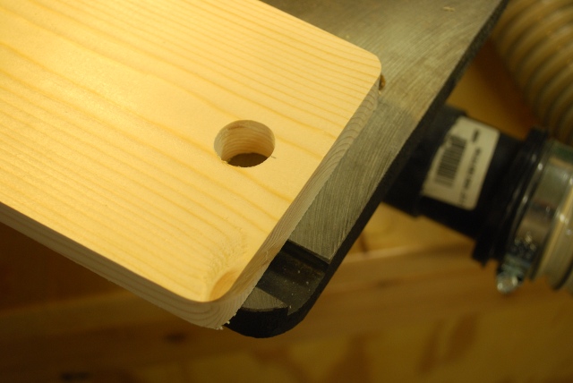
See, a neat 3/4" hole with no tear out.
Forsner bits are pretty good at drilling clean holes even without drilling both sides, but this technique ensures a clean result.
I'll sand the inside of the hole just to make it a little cleaner but this isn't bad.
|
|
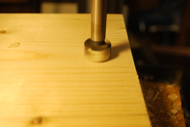
The 1-/14" hole for the "heel grabber".
|
|
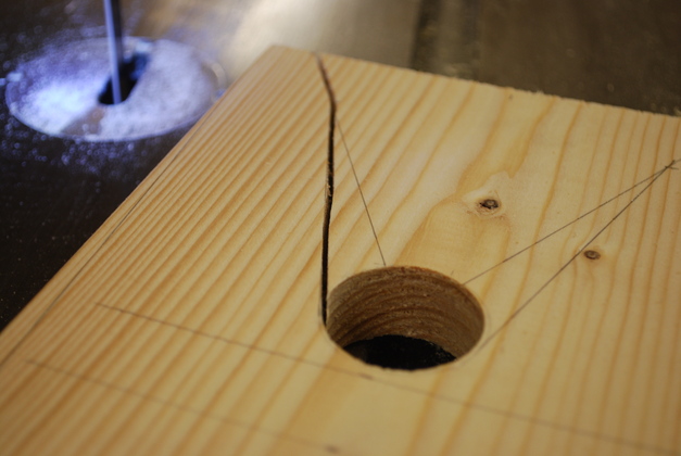
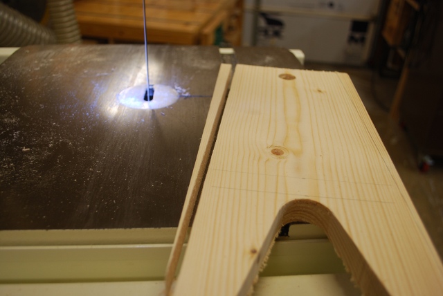
Here I have sawn one side of the "heel grabber".
|
|
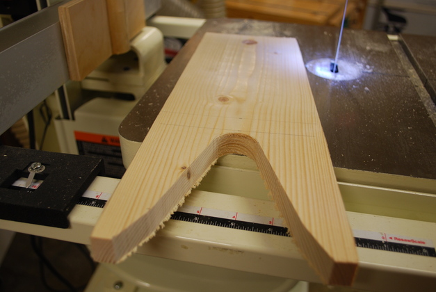
The "heel grabber" is cut out, and one of the "taper lines".
|
|
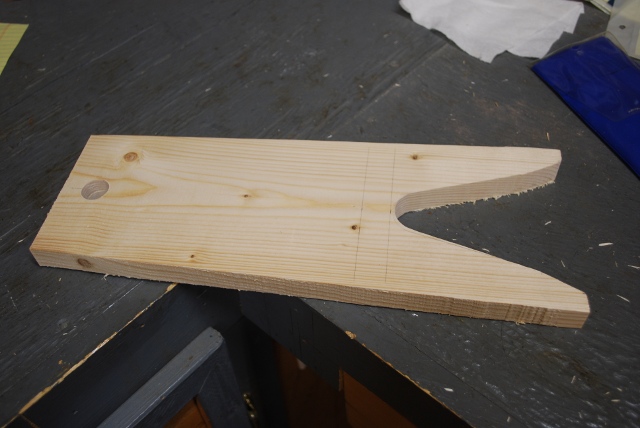
One bottom board completely cut out.
|
|
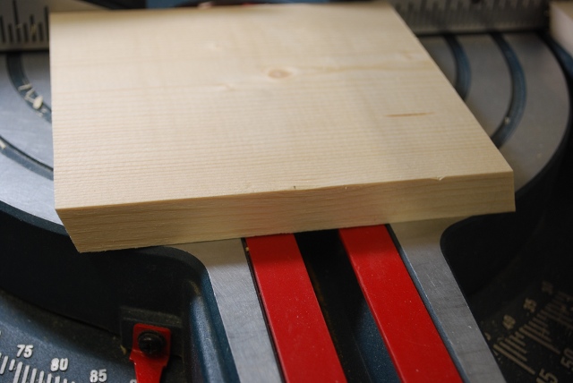
A top board ready to sand (to clean up the bandsaw cuts).
|
|
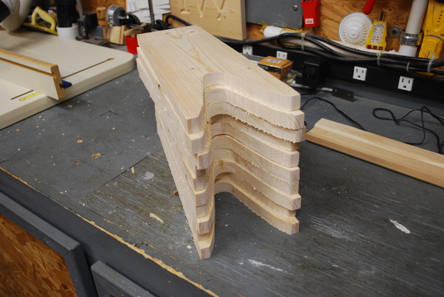
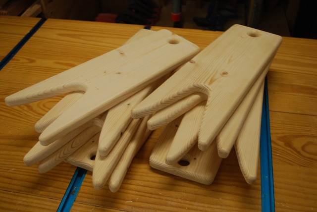
All 10 of the main boards ready to sand.
|
|
I've started sanding and can still see the marks left by the bandsaw on the inside of the "heel grabber".
You'll notice the little curls of wood left over from bandsawing are still there too.
Most of the times you use the bandsaw you must leave material so you can sand it smooth.
This bandsaw is used for resawing so it only has 3-TPI, my 10" bandsaw has 14-TPI.
The small bandsaw saws smoother but the larger one saws much faster and I had 10 of these to saw.
|
|
And the bandsaw marks along the area where I cut off the "taper" section.
|
|
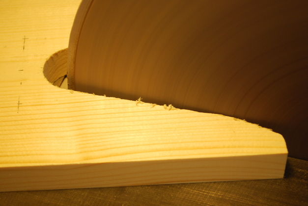
I begin to sand the inside of the "heel grabber".
|
|
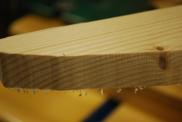
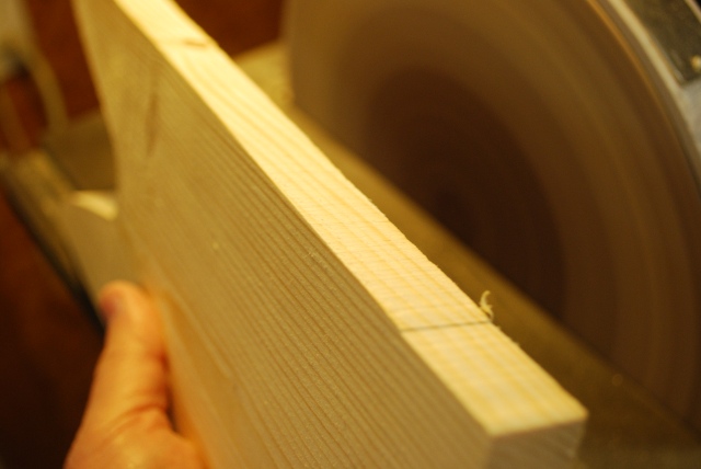
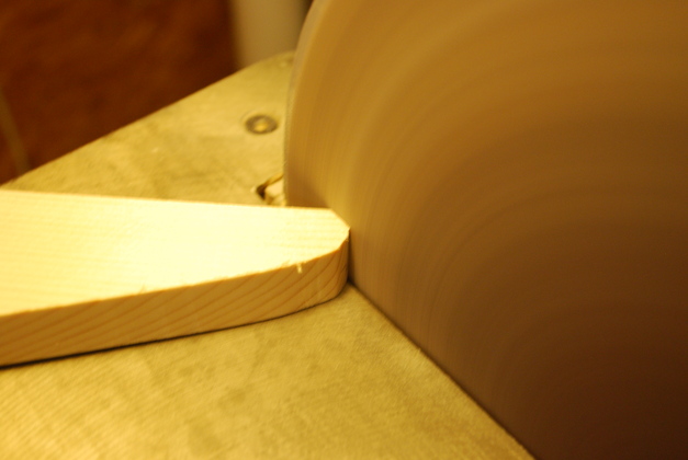
Sanding the taper cut on the outside of the main board.
Notice the side being cleaned up is almost parallel to the disk sander's face, I exaggerated the angle just to show it wasn't flat up against the disk.
This technique makes for a clean straight edge.
|
|
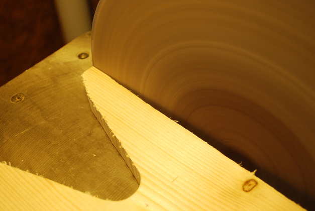
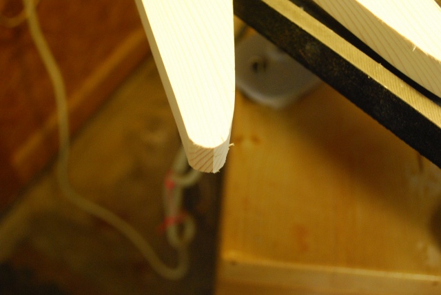
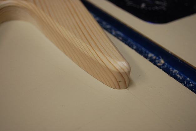
Start to round off the tip of the "heel grabber".
|
|
Rounding off the back corner of the main board.
|
|
Back end of main board after rounding off the corners.
|
|
Used disk sander to round off tip of "heel grabber".
|
|
I begin rounding off all the edges, top and bottom.
|
|
Rounding off the tip of the "heel grabber".
|
|
Down the long side.
|
|
Around the back corner.
|
|
A main board with one side rounded.
|
|
A look with the rounded edges up.
|
|
Rounded edges vs only the corners rounded.
|
|
All edges rounded.
|
|
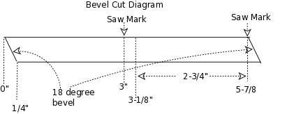
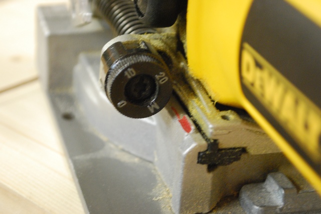
I set my mitre saw on an 18° angle and started cutting out the support pieces.
I made a trial cut on a piece of scrap and measured the kerf (width of cut), it was 1/8".
I marked the 1x6 3" from the end and another 2-3/4" plus 1/8" or 2-7/8" from the end (please see diagram below).
I cut all the diagonals, then reset the saw and cut the vertical cuts.
It would save some measuring if you just made an 18° bevel cut then reset and made a vertical cut, but I wanted all the 18° cuts exactly the same.
|
|
Note the "Saw Mark"s the one in the center is for a vertical cut.
|
|
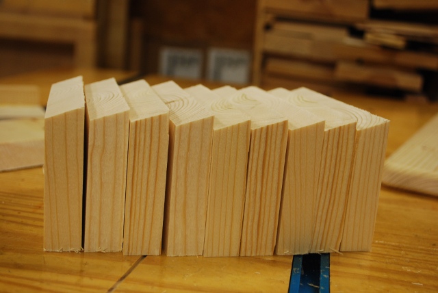
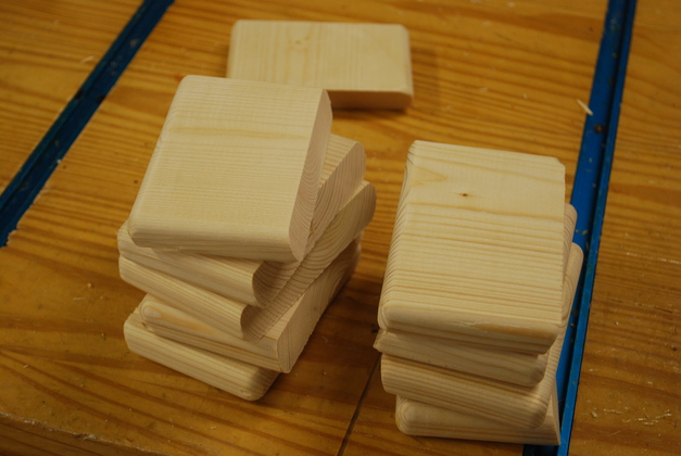
All 10 support pieces after cutting the bevels and ready to cut the width to 4-1/2" wide, then round off the edges.
|
|
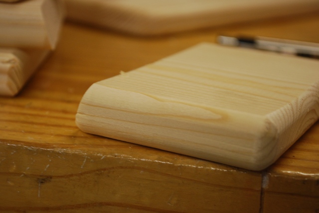
Rounded support pieces on all three edges and corners except the beveled end, on the left.
|
|
The whole pile of supports, beveled and rounded.
|
|
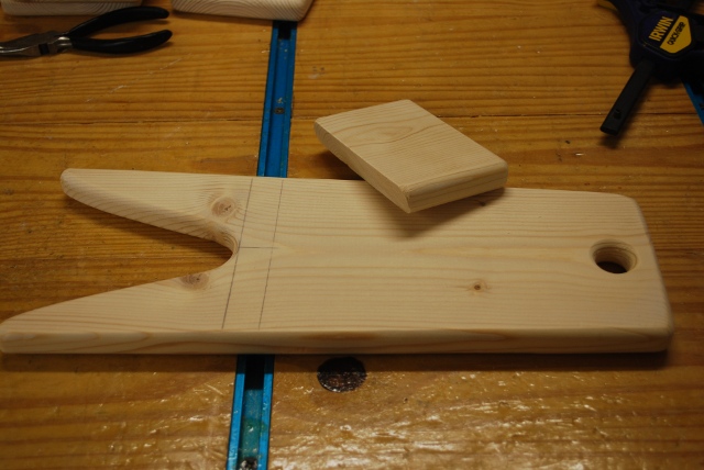
Ready to attach the support piece.
|
|
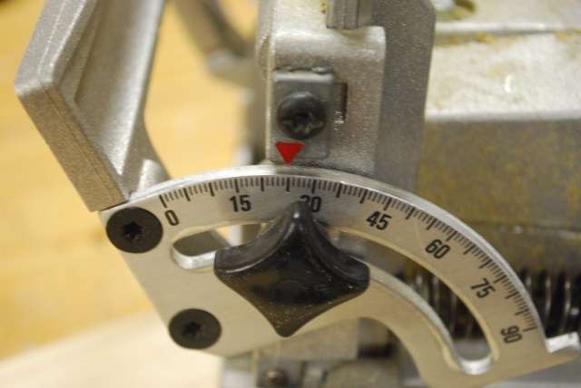
I set the effective angle of the biscuit jointer to the same as the bevel on the support piece.
I set the beveled support piece on the mainboard, then matched the angle by setting the fence on the biscuit cutter.
|
|
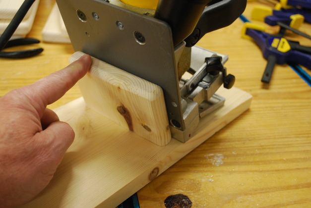
See how the fence on the biscuit cutter isn't down against the base board.
This means the fence doesn't set the true angle of the blade in this case, so I had to adjust the angle to compensate.
|
|
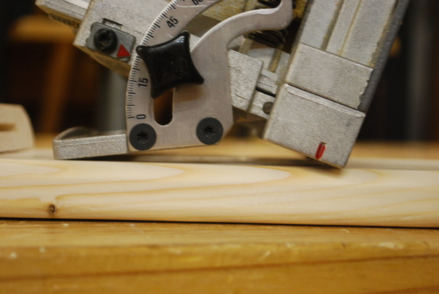
I ended up having to set the biscuit cutter on 25° to get an effective angle of 18° (match the support bevel).
|
|
I also had to set the depth to maximum since the biscuit cutter's base isn't up against the main board or bevel of the support piece.
|
|
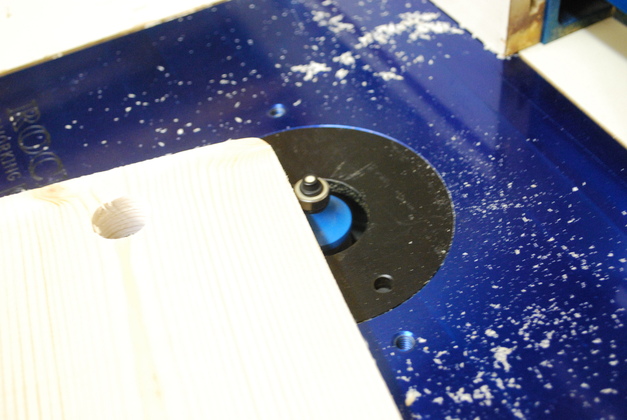
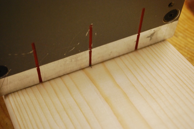
I made a small mark on the centerline of the main board at the transverse line for the support piece.
See the slot cutter aligned with marks on the main board.
If you set the slot cutter's base flat on a board, the blade is 3/8" above the board.
I use this when I have to cut straight into a flat board with no corner to reference.
|

|
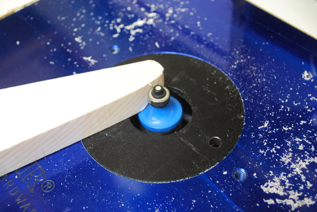
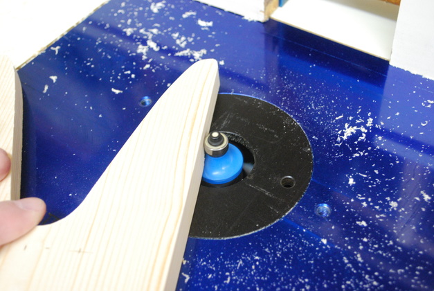
Slot cutter's base aligned with the edge of the support piece.
|
|
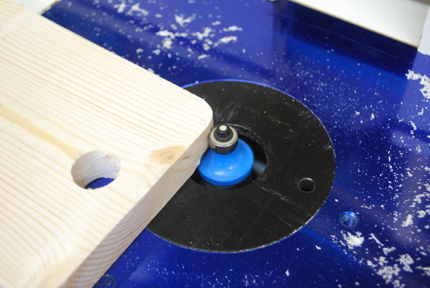
Both support and base board slotted.
The slots here can be called mortises and the the biscuit a "loose tenon".
|
|
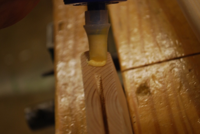
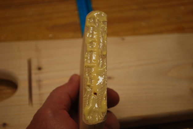
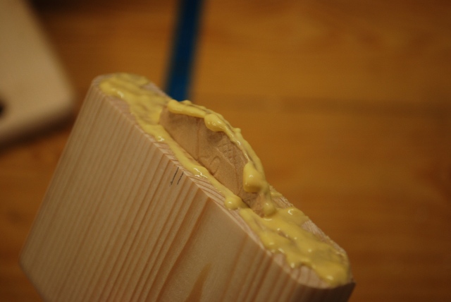
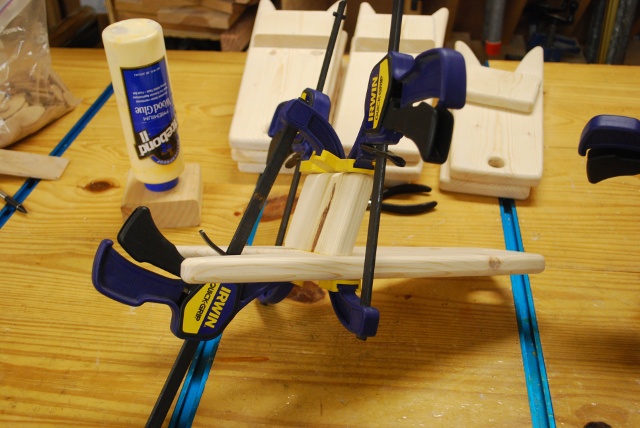
Run a bead of glue across the top of the support piece.
|
|
Notice how I get a lot of glue down into the slot.
|
|
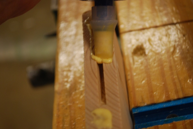
Glue on and in the slot of the support piece.
Spread a thin layer of glue all over the mating surface, with extra inside the slot.
I actually have a little too much glue on this, the extra will squeeze out when I clamp them together.
|
|
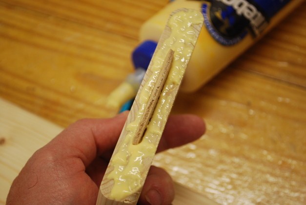
Insert the biscuit.
|
|
Run a good bead of glue across the top of the biscuit.
This will make sure there is glue in the slot in the main board.
Since I only glue one side of a joint like this, there needs to be enough glue to cover the joint and inside the slot on the opposite board.
|
|
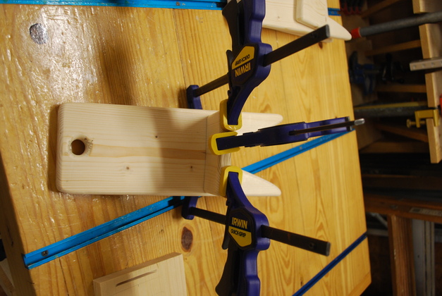
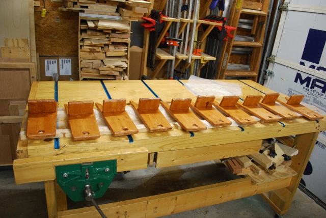
I initially start with the center clamp to pull the biscuit into both mortises, making sure the center mark is aligned.
The center clamp is almost directly aligned with the support piece (angle).
The two side clamps are left on and make sure the support piece is flat and "snugged up" to the main board.
If your main board wasn't quite flat, this shoule pull it flat and hold it after the glue dries.
|
|
Clamps seen from a little different angle.
You can see the angle of the center clamp matches the angle of the support piece.
|
|
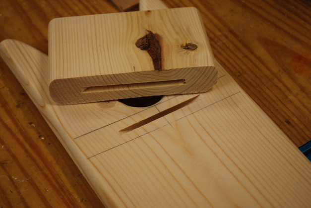
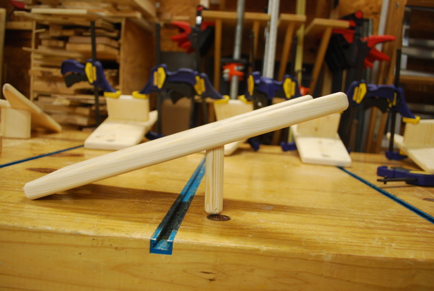
Here is one of the boot jacks after gluing, notice the support piece is perpendicular to the bench instead of perpendicular to the main board.
|
|
As seen from above.
Note there are no screws on top, like the prototype, the loose tennon and glue is plenty to hold it together.
|
|
the "heel grabber".
|
|
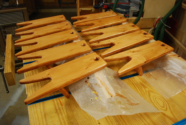
Bottoms stained/painted.
I used Varathane Plus Poly, Light Walnut Semi Gloss to get this color and sheen.
Varathane Plus Poly is a water based polyurethane with stain.
After using the Varathane Plus Poly, I have decided it doesn't work for me.
It doesn't actually stain the wood, it is way too thin and is easily scratched.
It is so thin that when you apply it, and it pulls the wood grain up so it needs sanding, any sanding at all strips down to the wood and requires another coat which pulls up the wood grain again, etc.!!!
This does work if you put on a clear coat of poly then apply the varathane after it dries.
|
|
Tops stained/painted.
|

|
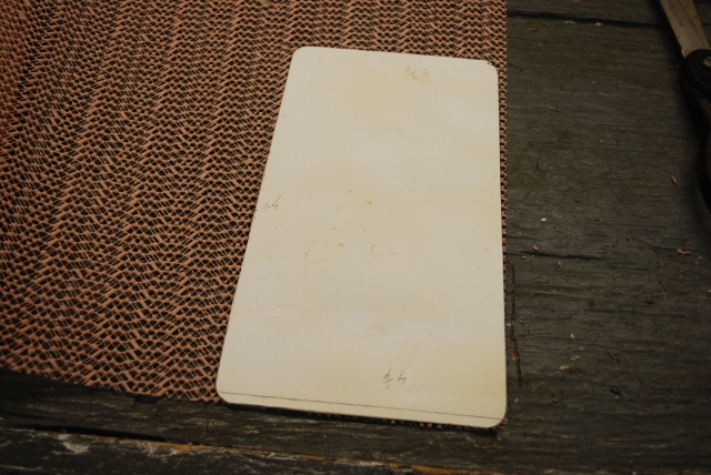
I plan to put a non-skid mat on top of the main board to give a little bit more traction when you have one foot on top, pulling off the other boot.
I cut out a pattern for the non-skid top from cardboard, it's 7" long, 4-1/2" wide at the top, and 3-1/2" at the bottom with rounded corners.
Please see the Pistol Cocker project for more info.
|
|
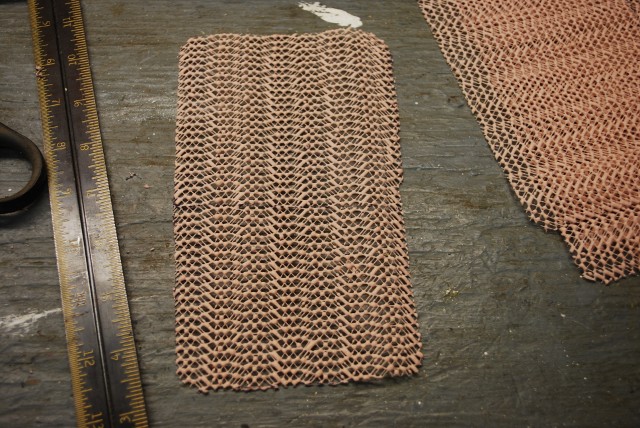
Used the pattern to mark the rubbery shelf liner.
|
|
Here is one of the mats I plan to place in the fresh poly on top of the main board.
|
|
|
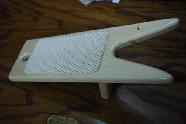
Finished Boot Jack.
Betty says the pad makes it even easier to get your boot off by not letting your other foot slip.
|
|
Slightly higher view.
|
|
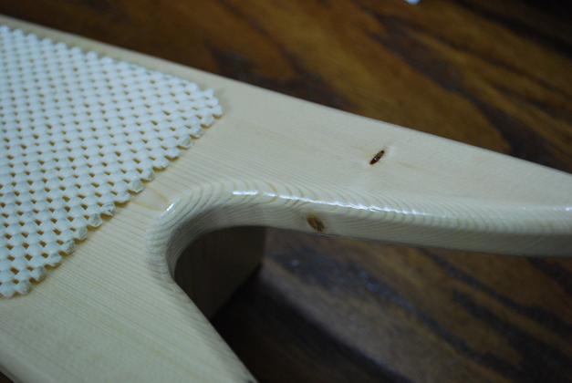
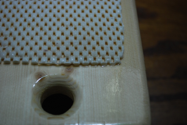
Closer shot of heel grabber and pad.
|
|
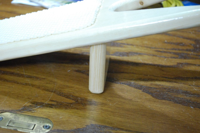
You can see how the beveled support piece sits straight up and down.
|
|
Underside of bootjack with support angled.
|
|
You can see how I put a lot of poly under the pad and even got some on top around the edge.
|