LED Music Visualizer - 2
From: https://community.element14.com/challenges-projects/project14/opampapalooza/b/blog/posts/led-music-visualizer---blog-2-filter-designs
LED Music visualizer
Blog 2: Filter Designs and Simulations
rsjawale24
rsjawale24
26 Apr 2022
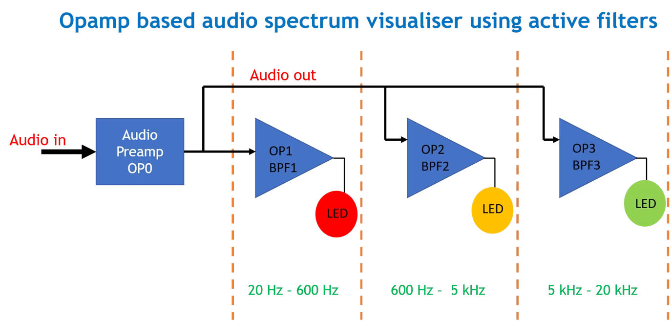
In my last blog (part 1) I introduced the overall idea of the project. The
idea was to split the audio spectrum from 20 Hz to 20 kHz using three active
filters and each filter's output is connected to LEDs thereby making a LED
music visualizer. I also simulated 3 basic filters (LPF,BPF, and HPF) and an
active low pass filter to demonstrate the working of active filters.
In this blog, I will do the calculations for the values of the components
required to build the active filters and run some simulations before the
final hardware build of the circuit. I will be using RC filters with
Butterworth response.
 image
The first block in the design is the pre-amplifier. A pre-amp is needed as
I'm planning to use the audio out of a smartphone which is in the range of
few millivolts. This signal needs to be amplified such that it can be fed to
the three opamp filters.
The preamp is a very basic non-inverting opamp amplifier with a voltage gain
of about 4-5.
Next, step is to decide the bands for the filters.
image
The first block in the design is the pre-amplifier. A pre-amp is needed as
I'm planning to use the audio out of a smartphone which is in the range of
few millivolts. This signal needs to be amplified such that it can be fed to
the three opamp filters.
The preamp is a very basic non-inverting opamp amplifier with a voltage gain
of about 4-5.
Next, step is to decide the bands for the filters.
Audio Bands
First, the audio signal (20 Hz - 20 kHz) is split into three bands as
follows-
| Band | Frequency
|
| Band 1 | 20 Hz - 480 Hz
|
| Band 2 | 480 Hz - 3 kHz
|
| Band 3 | 3 kHz - 20 kHz
|
Since the audio spectrum is limited to 20 Hz - 20 kHz, the first band can be
filtered out using a low pass filter with a cutoff freq of 480 Hz, this LPF
will allow all the frequencies from 20Hz to 480 Hz and attenuate the
frequencies above 480 Hz. This low-frequency spectrum of the audio is also
known as "Bass". For band 2, a band pass filter is designed such that it can
filter out the 480 Hz - 3 kHz band. This band mostly contains the voice or
"vocals". Lastly, for band 3, a high pass filter is used with a cutoff freq
of 3 kHz meaning that it will attenuate all signals below 3 kHz. This band
is also known as "treble".
Now that we have decided on the bands, let's move to filter design.
Filter Design
Active Low Pass Filter
In the last blog, I briefly introduced the active low pass filter circuit.
Considering the same circuit and as decided from the above table, Band 1
means a cutoff freq. of 480 Hz, which means fc = 1/(2*pi*R*C) = 480 Hz.
Since we have a huge range of standard resistors available but the range of
capacitors is limited, a standard value of C is chosen which is 0.1 uF.
By doing the calculations, the value of R is found to be 3315.72 ohms, so
the closest standard value for R is chosen as 3.3 kohms.
Hence, design values for the active LPF are R = 3.3k and C = 0.1 uF. This
gives the cutoff freq. of 482 Hz which is quite near to the actual cutoff
freq.
Now, to set the gain of the filter, a nominal gain of about 2-3 works fine.
For calculating the resistor values for gain, the simple gain formula for
non-inverting opamp is used.
Active Band Pass Filter
Next, a band pass filter is designed. A band pass filter filters out a band
of frequencies which means it has two cutoff freqs, the lower cutoff (fc1)
and the higher cutoff (fc2). Here, from the table, fc1 = 480 Hz and fc2 = 3
kHz.
Hence, using the same formula of LPF, the R and C values for fc1 and fc2 are
found to be R1 = 500 ohms and C1 = 0.1 uF and R2 = 3.3k and C2 = 0.1uF. This
will give the values of fc1 = 3.18 kHz and fc2 = 482 Hz.
Active High Pass Filter
For the last block, a high pass filter is designed. The formula remains the
same. The fc for HPF from the table is fc = 3kHz. The values for R and C are
decided as R = 500 ohms and C = 0.1 uF.
Simulation Results
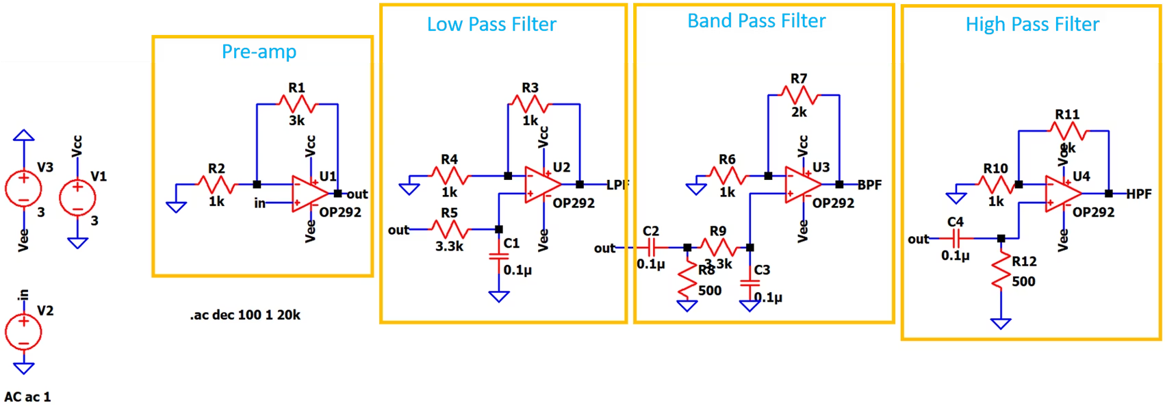
I simulated the entire circuit in LT spice to check if it works properly.
The simulation setup is AC analysis to check the filter response. The opamps
work on a dual rail power supply of +/- 3V. For simulating the audio signal,
I have used an AC source.
The below image shows the final circuit diagram along with the individual
blocks labeled.
 image
The preamp gives a voltage gain of 4 (non-inverting configuration) and the
signal from the output of this preamp is then fed to three filter blocks.
The outputs of these filters are connected to LEDs(not shown in Ltspice).
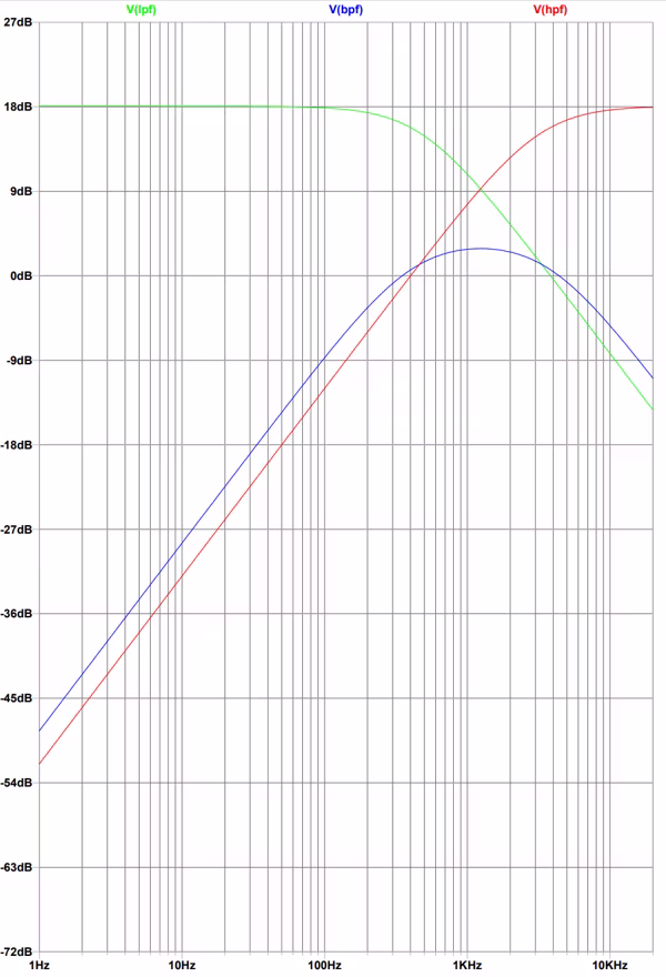
Below are the simulation results -
image
The preamp gives a voltage gain of 4 (non-inverting configuration) and the
signal from the output of this preamp is then fed to three filter blocks.
The outputs of these filters are connected to LEDs(not shown in Ltspice).
Below are the simulation results -
 image
It can be seen from the frequency response plots, that the filters are
working correctly. If we compare the results of the active LPF with the
passive LPF from my last blog, it can be seen that here the gain of the
active LPF is around 18dB whereas in the case of the passive filter it was
around 0dB due to the lossy filter components and no active components to
amplify the filtered signal. The same is the case for other filters too.
Another thing to note is that due to the presence of two resistors in BPF,
the gain is less due to loss in resistors. This can be compensated by
adjusting the gain of the opamp of the BPF block.
In the next blog, I will construct the circuit on a breadboard and publish
the results along with the video. Stay tuned!
image
It can be seen from the frequency response plots, that the filters are
working correctly. If we compare the results of the active LPF with the
passive LPF from my last blog, it can be seen that here the gain of the
active LPF is around 18dB whereas in the case of the passive filter it was
around 0dB due to the lossy filter components and no active components to
amplify the filtered signal. The same is the case for other filters too.
Another thing to note is that due to the presence of two resistors in BPF,
the gain is less due to loss in resistors. This can be compensated by
adjusting the gain of the opamp of the BPF block.
In the next blog, I will construct the circuit on a breadboard and publish
the results along with the video. Stay tuned!
