The Full-Wave Rectifier To rectify both half cycles of a sine wave, the full-wave rectifier uses two diodes, one for each half of the cycle. It also uses a transformer with a center-tapped secondary winding. The full-wave rectifier is like two back-to-back half-wave rectifiers. Following image shows a Full-wave rectifier circuit.
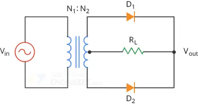 fullwave rectifier
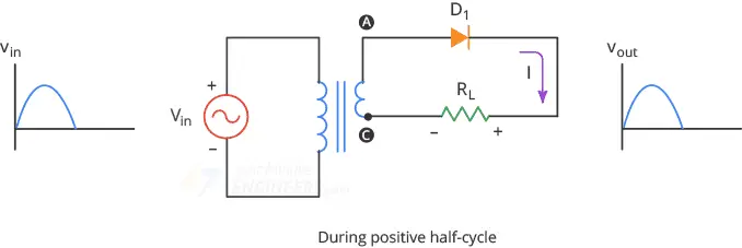
This circuit’s operation is easily understood one half-cycle at a time.
Consider the first half-cycle, when point A is positive with respect to C. At
this time, D1 is forward biased and D2 is reverse biased. Therefore, only the
top half of the transformer’s secondary winding carries current during this
half-cycle. This produces a positive load voltage across the load resistor.
fullwave rectifier
This circuit’s operation is easily understood one half-cycle at a time.
Consider the first half-cycle, when point A is positive with respect to C. At
this time, D1 is forward biased and D2 is reverse biased. Therefore, only the
top half of the transformer’s secondary winding carries current during this
half-cycle. This produces a positive load voltage across the load resistor.
 fullwave rectifier during positive half cycle
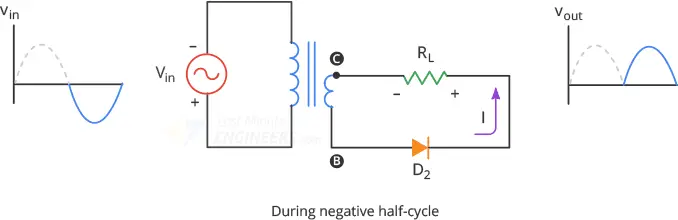
During the next half-cycle, the source voltage polarity reverses. Now, point B
is positive with respect to C. This time, D2 is forward biased and D1 is reverse
biased. As you can see, only the other half of the transformer’s secondary
winding carry current. This also produces a positive load voltage across the
load resistor as before.
fullwave rectifier during positive half cycle
During the next half-cycle, the source voltage polarity reverses. Now, point B
is positive with respect to C. This time, D2 is forward biased and D1 is reverse
biased. As you can see, only the other half of the transformer’s secondary
winding carry current. This also produces a positive load voltage across the
load resistor as before.
 fullwave rectifier during negative half cycle
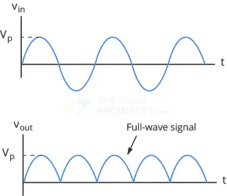
As a result, the rectified load current flows during both half-cycles due to
which we get Full-wave signal across the load.
fullwave rectifier during negative half cycle
As a result, the rectified load current flows during both half-cycles due to
which we get Full-wave signal across the load.
 fullwave signal
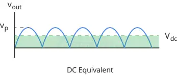
DC Value of a Full-Wave Signal Since the full-wave rectifier produces an output during both half-cycles, it has twice as many positive cycles as the half-wave signal. As a result the DC or average value is also twice as much:
 dc equivalent of fullwave signal
The average value of the signal over one cycle is calculated with the below
formula:
dc equivalent of fullwave signal
The average value of the signal over one cycle is calculated with the below
formula:
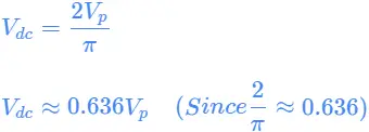 This equation tells us that the DC value of a full-wave signal is about 63.6% of
the peak value. For example, if the peak voltage of the full-wave signal is 10V,
the DC voltage will be 6.36V
When you measure the full-wave signal with a DC voltmeter, the reading will
equal the average DC value.
This equation tells us that the DC value of a full-wave signal is about 63.6% of
the peak value. For example, if the peak voltage of the full-wave signal is 10V,
the DC voltage will be 6.36V
When you measure the full-wave signal with a DC voltmeter, the reading will
equal the average DC value.
A Second-order Approximation In reality, we do not get a perfect full-wave voltage across the load resistor. Because of the barrier potential, the diode does not turn on until the source voltage reaches about 0.7V. So, the output voltage is 0.7V lower than the ideal peak output voltage.
Output Frequency The full-wave rectifier inverts each negative half cycle, doubling the number of positive half cycles. Because of this, full-wave output has twice as many cycles as the input. Therefore the frequency of the full-wave signal is double the input frequency.
 For example, if the line frequency is 60Hz, the output frequency will be 120Hz.
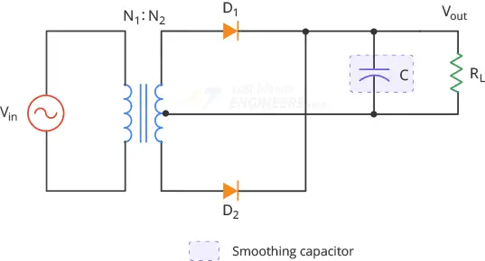
Filtering the Output of a Rectifier The output we get from a full-wave rectifier is a pulsating DC voltage that increases to a maximum and then decreases to zero. We do not need this kind of DC voltage. What we need is a steady and constant DC voltage, free of any voltage variation or ripple, as we get from the battery. To obtain such a voltage, we need to filter the full-wave signal. One way to do this is to connect a capacitor, known as a smoothing capacitor, across the load resistor as shown below.
 fullwave rectifier with smoothing capacitor
Initially, the capacitor is uncharged. During the first quarter-cycle, the diode
D1 is forward biased, so the capacitor starts charging. The charging continues
until the input reaches its peak value. At this point, the capacitor voltage
equals Vp.
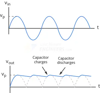
After the input voltage reaches its peak, it begins to decrease. As soon as the
input voltage is less than Vp, the voltage across the capacitor exceeds the
input voltage which turns off the diode.
As the diode is off, the capacitor discharges through the load resistor and
supplies the load current, until the next peak is arrived.
When the next peak arrives, the diode D2 conducts briefly and recharges the
capacitor to the peak value.
fullwave rectifier with smoothing capacitor
Initially, the capacitor is uncharged. During the first quarter-cycle, the diode
D1 is forward biased, so the capacitor starts charging. The charging continues
until the input reaches its peak value. At this point, the capacitor voltage
equals Vp.
After the input voltage reaches its peak, it begins to decrease. As soon as the
input voltage is less than Vp, the voltage across the capacitor exceeds the
input voltage which turns off the diode.
As the diode is off, the capacitor discharges through the load resistor and
supplies the load current, until the next peak is arrived.
When the next peak arrives, the diode D2 conducts briefly and recharges the
capacitor to the peak value.
 filtered fullwave signal
Disadvantages One of the disadvantages of this center-tapped full-wave rectifier design is the necessity of a transformer with a center-tapped secondary winding. In high-power rectification, however, the cost and size of such transformers increase substantially. That’s why, the center-tap rectifier design is only seen in low-power applications. Another disadvantage is that because of the center tap, only half of the secondary voltage is used for rectification. To overcome these disadvantages four diodes are connected together in a “bridge” configuration to produce a Full Wave Bridge Rectifier as discussed in the next tutorial.