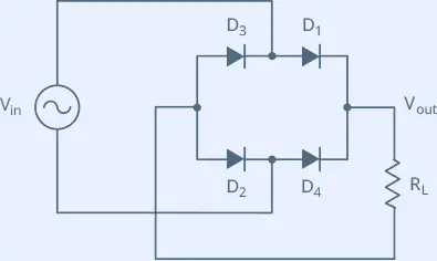
The Full-Wave Bridge Rectifier To rectify both half-cycles of a sine wave, the bridge rectifier uses four diodes, connected together in a “bridge” configuration. The secondary winding of the transformer is connected on one side of the diode bridge network and the load on the other side. Following image shows a bridge rectifier circuit.
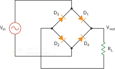 fullwave bridge rectifier
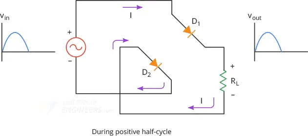
This circuit’s operation is easily understood one half-cycle at a time.
During positive half cycle of the source, diodes D1 and D2 conduct while D3 and
D4 are reverse biased. This produces a positive load voltage across the load
resistor (note the plus-minus polarity across the load resistor).
fullwave bridge rectifier
This circuit’s operation is easily understood one half-cycle at a time.
During positive half cycle of the source, diodes D1 and D2 conduct while D3 and
D4 are reverse biased. This produces a positive load voltage across the load
resistor (note the plus-minus polarity across the load resistor).
 bridge rectifier during positive half cycle
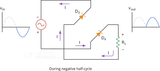
During the next half-cycle, the source voltage polarity reverses. Now, D3 and D4
are forward biased while D1 and D2 are reverse biased. This also produces a
positive load voltage across the load resistor as before.
bridge rectifier during positive half cycle
During the next half-cycle, the source voltage polarity reverses. Now, D3 and D4
are forward biased while D1 and D2 are reverse biased. This also produces a
positive load voltage across the load resistor as before.
 bridge rectifier during negative half cycle
Note that regardless of the polarity of the input, the load voltage has the same
polarity and the load current is in the same direction.
In this way the circuit converts the AC input voltage to the pulsating DC output
voltage.
bridge rectifier during negative half cycle
Note that regardless of the polarity of the input, the load voltage has the same
polarity and the load current is in the same direction.
In this way the circuit converts the AC input voltage to the pulsating DC output
voltage.
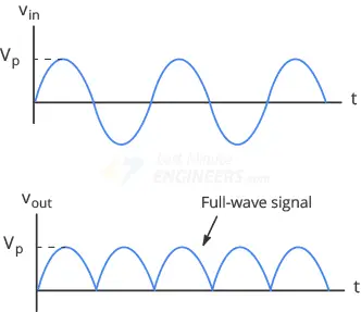 fullwave signal
If it is frustrating for you to remember the proper layout of the diode in a
bridge rectifier circuit, you can refer to an alternative representation of the
circuit. This is exactly the same circuit except all diodes are horizontal and
point in the same direction.
fullwave signal
If it is frustrating for you to remember the proper layout of the diode in a
bridge rectifier circuit, you can refer to an alternative representation of the
circuit. This is exactly the same circuit except all diodes are horizontal and
point in the same direction.
 alternate representation of bridge rectifier
DC Value of a Full-Wave Signal Because a bridge rectifier produces a full-wave output, the formula for calculating average DC value is the same as that given for the full-wave rectifier:
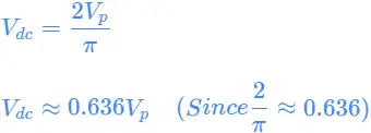 This equation tells us that the DC value of a full-wave signal is about 63.6
percent of the peak value. For example, if the peak voltage of the full-wave
signal is 10V, the dc voltage will be 6.36V
When you measure the half-wave signal with a DC voltmeter, the reading will
equal the average DC value.
This equation tells us that the DC value of a full-wave signal is about 63.6
percent of the peak value. For example, if the peak voltage of the full-wave
signal is 10V, the dc voltage will be 6.36V
When you measure the half-wave signal with a DC voltmeter, the reading will
equal the average DC value.
A Second-order Approximation In reality, we do not get a perfect full-wave voltage across the load resistor. Because of the barrier potential, the diode does not turn on until the source voltage reaches about 0.7V. And as the bridge rectifier operates two diodes at a time, two diode drops (0.7 * 2 = 1.4V) of the source voltage are lost in the diode. So the peak output voltage is given by:
Output Frequency The full-wave rectifier inverts each negative half cycle, doubling the number of positive half cycles. Because of this, full-wave output has twice as many cycles as the input. Therefore the frequency of the full-wave signal is double the input frequency.
 For example, if the line frequency is 60Hz, the output frequency will be 120Hz.
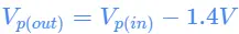
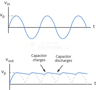
Filtering the Output of a Rectifier The output we get from a full-wave rectifier is a pulsating DC voltage that increases to a maximum and then decreases to zero. We do not need this kind of DC voltage. What we need is a steady and constant DC voltage, free of any voltage variation or ripple, as we get from the battery. To obtain such a voltage, we need to filter the full-wave signal. One way to do this is to connect a capacitor, known as a smoothing capacitor, across the load resistor as shown below.
 bridge rectifier with smoothing capacitor
Initially, the capacitor is uncharged. During the first quarter-cycle, diodes D1
and D2 are forward biased, so the capacitor starts charging. The charging
continues until the input reaches its peak value. At this point, the capacitor
voltage equals Vp.
After the input voltage reaches its peak, it begins to decrease. As soon as the
input voltage is less than Vp, the voltage across the capacitor exceeds the
input voltage which turns off the diodes.
As the diodes are off, the capacitor discharges through the load resistor and
supplies the load current, until the next peak is arrived.
When the next peak arrives, diodes D3 and D4 conduct briefly and recharges the
capacitor to the peak value.
bridge rectifier with smoothing capacitor
Initially, the capacitor is uncharged. During the first quarter-cycle, diodes D1
and D2 are forward biased, so the capacitor starts charging. The charging
continues until the input reaches its peak value. At this point, the capacitor
voltage equals Vp.
After the input voltage reaches its peak, it begins to decrease. As soon as the
input voltage is less than Vp, the voltage across the capacitor exceeds the
input voltage which turns off the diodes.
As the diodes are off, the capacitor discharges through the load resistor and
supplies the load current, until the next peak is arrived.
When the next peak arrives, diodes D3 and D4 conduct briefly and recharges the
capacitor to the peak value.
 filtered fullwave signal
Disadvantage The only disadvantage of the bridge rectifier is that the output voltage is two diode drops (1.4V) less than the input voltage. This disadvantage is only a problem in very low voltage power supplies. For instance, if the peak source voltage is only 5V, the load voltage will have a peak of only 3.6V. But if the peak source voltage is 100 V, the load voltage will be close to a perfect full-wave voltage (the diode drops are negligible).