BCD Clock
For years we have had an analog "atomic" clock, in our den, its round
(12" diameter) and a glass crystal in front of the face.
It hangs high on the den wall above the TV.
At night, when we are watching TV with only a small light on in the den, behind
us, I have trouble reading it because of the glare on the glass crystal.
So, I got the idea of building a large, easy to read clock.
I first thought of a larger round (about 2ft in diameter) clock, white with
black hands.
But, I had trouble finding a radio controlled (atomic) movement and large hands.
Then another thought occurred to me.
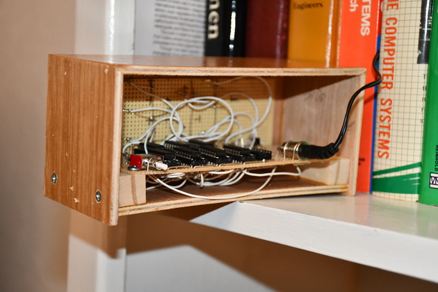
What if I built a small LED BCD clock to sit in the corner, on a bookshelf, I
could easily see it and Betty would still have her beloved radio controlled
clock, except of course, on spring forward and fall back days when the clock
just can't decide whether its DST or not.
I remembered the BCD clocks I built in the 70s and decided to try it.
In the olden days (SN74xx logic) we designed with lots of negative logic:
NAND, NOR gates, negative reset strobes, etc.
Lots of things have changed since I last designed a digital circuit.
Now, low power CMOS is available (CD4000), even the LEDs are more effecient.
My friend google and I did a little research, and saw a bunch of schematics,
but none did what I wanted but they all had some basic stuff and illustrated
some basic approaches to CMOS circuit design, which wasn't much different
from 74Sxx logic then I used ECL.
I got some available CMOS chip ideas from this page Instructables.com and
more ideas from Giuss schematic.
I found this page ("http://www.datasheet.free.fr/datasheets_cd.htm") which was a
quick way to find different circuit data sheets.
I started to bone up on CMOS ICs like the CD4000 family.
I didn't even have a resistor anymore so I went to Altex and bought phenolic perfboard,
resistor and capicitor assortments, IC sockets (14 and 16 pin), two push buttons
(momentary SPST NO), and a 9volt, switching, wall wart.
I'm goig to order the ICs from Mouser.com since Altex doesn't carry all of what I need.
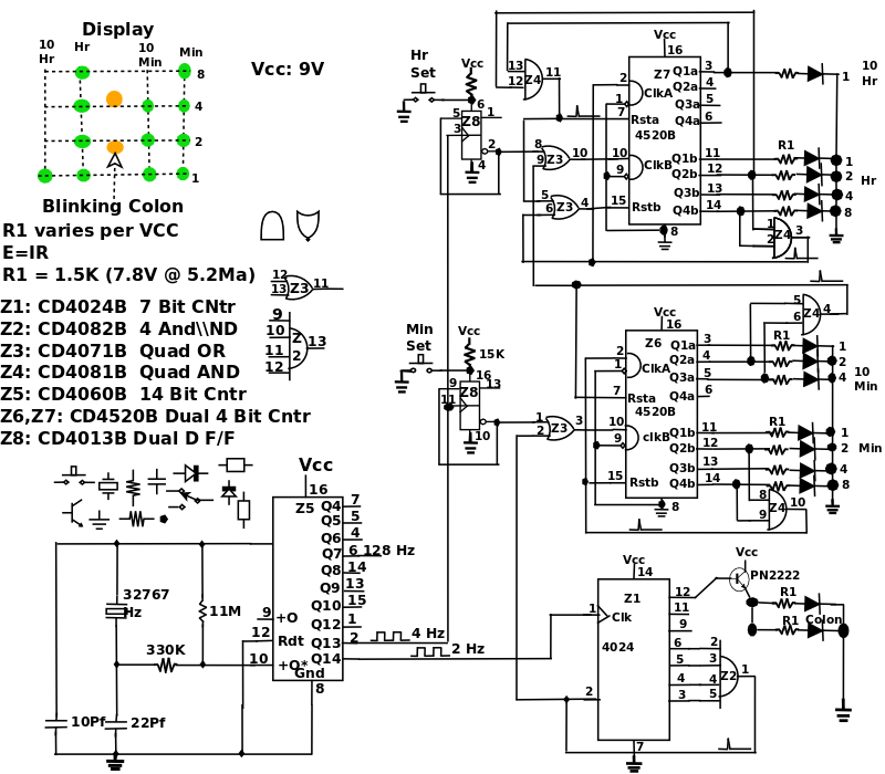
I drew a schematic that I think is good starting place, I'll build it and see where I am.
I thought about building my power supply from a transformer and bridge, but
switching wall warts are cheap and easy.
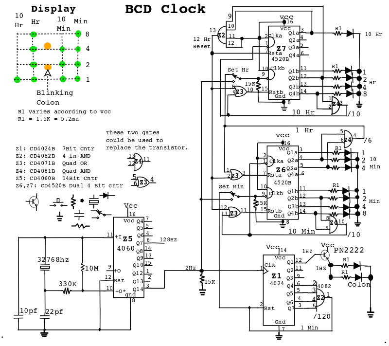
03/30/19, Better set circuit.
After running the clock for a while I didn't like the time set ckt.
So I removed the 12Hr reset line to the minute counters so I could wrap the
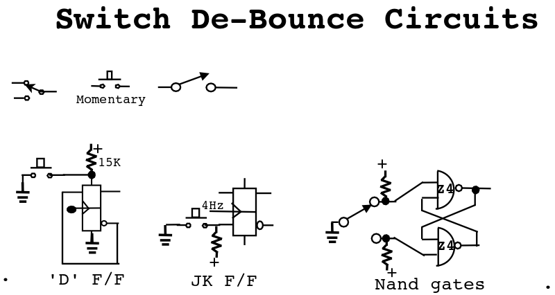
hours without resetting the minutes and added a dual D F/F to help debounce the
switches.
The F/F with a 4Hz clock should toggle at 2 Hz and debounce the push buttons
pretty well.
When the button is not being pushed the F/F will stay 'SET' (Q* low) so the
narrow pulses from the AND gates, resetting the lower counter and clocking the
upper counter will go through the OR gatesr.
When the button is pushed the F/F is allowed to toggle so the Q* is a 2Hz square wave.
A normally open SPST momentary push button would work, I already had the SPDT
push buttons, so...
You might see a double pulse if the 4Hz clock is just about to make a lo to hi
transtion when the button is bouncing.
The CD4013B has positive (hi level) set and reset inputs so as long as the
button is not pushed the resistor keeps the input hi forcing a 'SET' condition.
You could also use a J/K F/F circuit if thats what you happen to have.
04/02/19


Hooray, the new set circuit works.


Today I changed the clock circuits (added the CD4013 dual D F/F Z8) to use the
new set circuits and they work great.
From a power dissapation point:
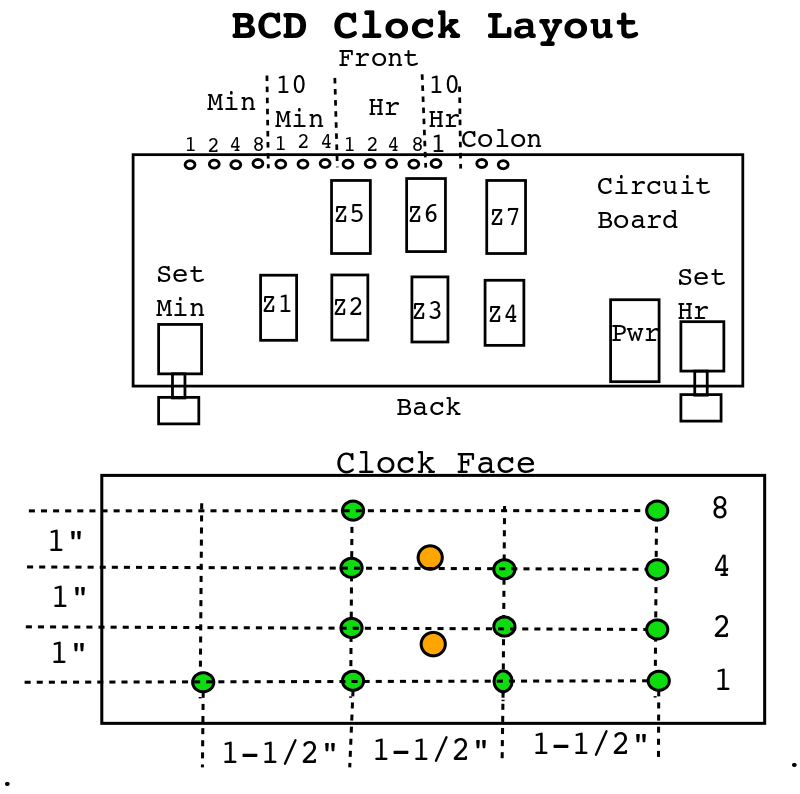
Back in my day (olden times) an LED was quite visible at 5ma, so If I run these
at 5ma and Vf = 2.1V, 10.5 mw per LED, or 105 mw if 10 were on (07:37 +colon).
The ICs dissipate about 3 mw ea. or 3 X 8 = 24 mw.
24mw + 105 = 129 mw peak total.
.129 w / 12 V = 10.75 MA
|
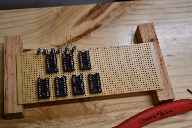
Beginning installing components.
|
|
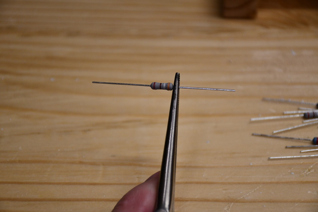
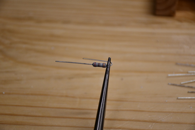
Resistor for LEDs.
|
|
Bending one lead.
I replaced these with 1500Ωs.
|
|
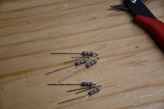
Resistors for LEDs having one lead bent.
|
|
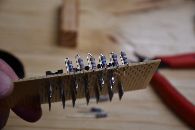
Beginning to install resistors in the circuit board.
I cut the wirewrap pins shorter, I couldn't use wirewrap, I couldn't find any real wirewrap wire.
|
|
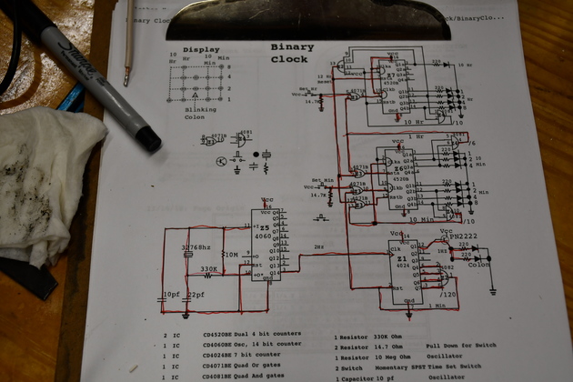
Red lining the schematic as I install wires.
This is a good way of making sure I get all the circuit wired correctly.
I've even seen real professional draftsmen red line a schematic as they lay out a PCB.
|
|
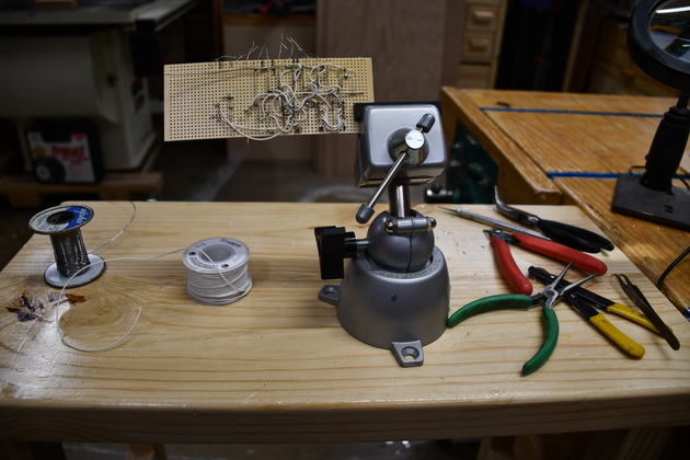
My setup for building the circuit board.
|
|
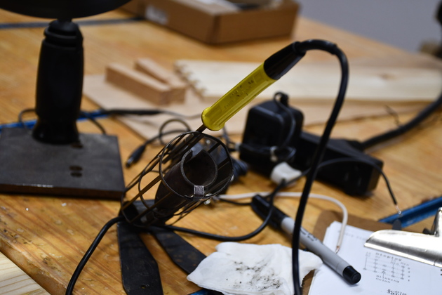
Antex Model C soldering iron with Ungar stand, I've had these for about 50 years.
|
|
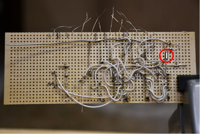
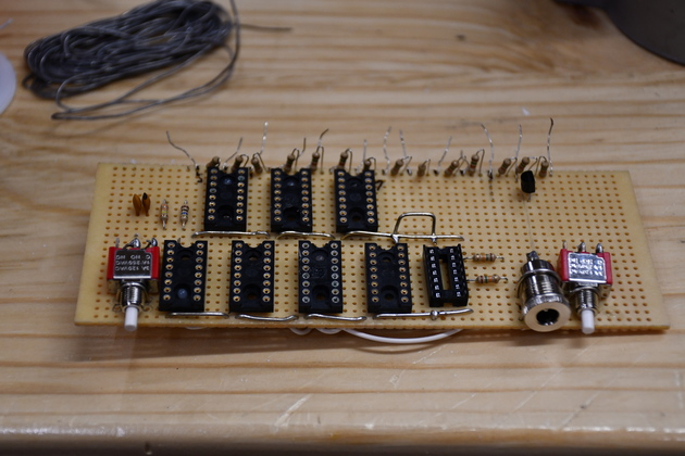
Beginning to install wires.
Note I have the Vcc on this side and ground on the other.
You can also see the 32768 Hz crystal (Red Cicrle) on the upper right of the board.
Yes, I finally started refering to cycles per second or frequency as hertz.


This is a clunky way of building a circuit board, but it works.
There are lots of faster ways using the new breadboards, or wirewrap but they're expensive or I couldn't find any wirewrap wire!
|
|
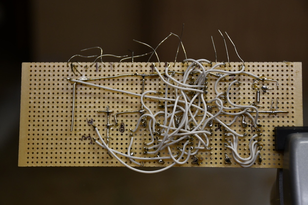
More wires.
|
|
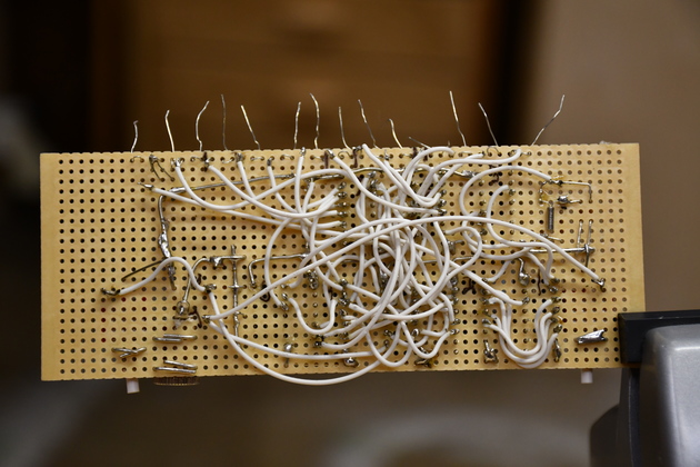
I mounted buttons and power receptical.
The tinned wires on top of the board are ground busses.


NOTE: just to the right of center a gound loop for testing.


Nuther Note: there is an extra 14 pin socket, thought I would need it but found a better way.
|
|
All wires done.
|
|
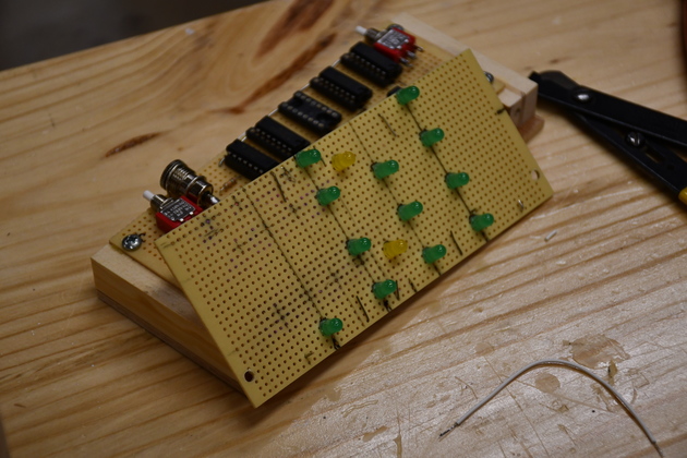
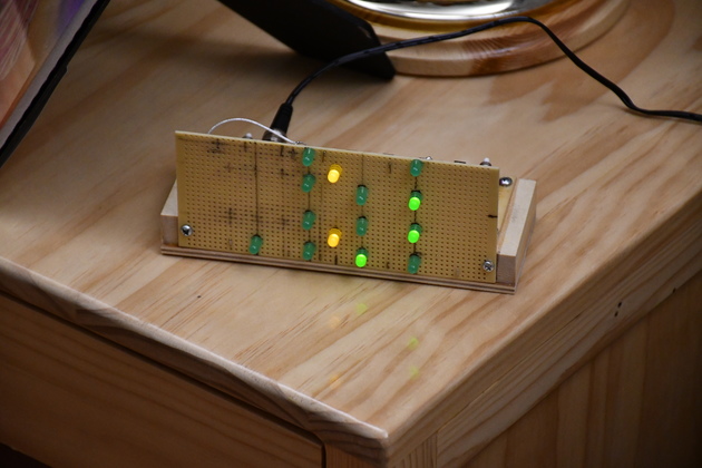
Display board with mounted LEDs.
|
|
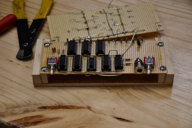
Wiring circuit board to display board.
The white wire on top is one of the two ground wires.
|
|
Operating clock.
It is 12:16.
|
|
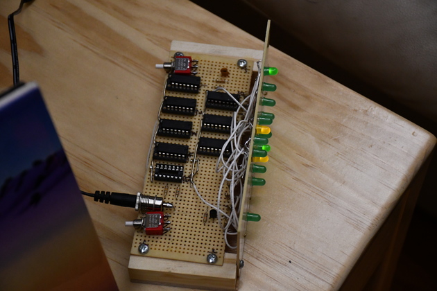
Internals visible.
|
|
Back view.
|
|
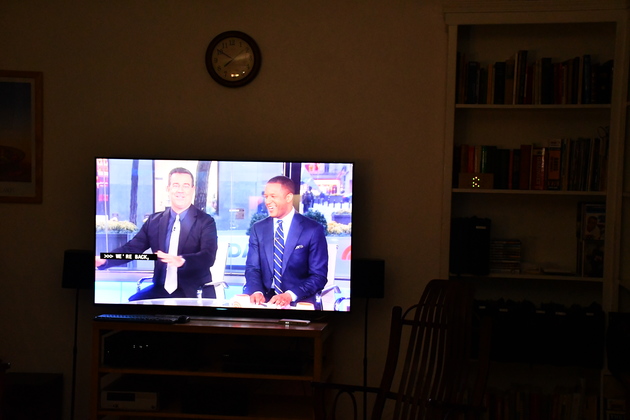
In the den with TV, its 7:50
You can also see the clock above the TV, at least the reflection from the crystal.
|

