USB Cables & Conns
From: https://en.wikipedia.org/wiki/USB_hardware
USB hardware
From Wikipedia, the free encyclopedia
This article is about the physical and electrical aspects of USB
connections. For the standard in general, see USB.
Various legacy USB connectors along a centimeter ruler for scale. From left
to right:
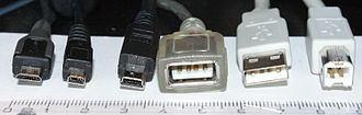
- Micro-B plug
- Proprietary UC-E6 connector used on many older Japanese cameras for both
USB and analog AV output
- Mini-B plug
- Standard-A receptacle, non-compliant because USB does not allow extensions
cables
- Standard-A plug
- Standard-B plug
The initial versions of the USB standard specified connectors that were easy
to use and that would have acceptable life spans; revisions of the standard
added smaller connectors useful for compact portable devices. Higher-speed
development of the USB standard gave rise to another family of connectors to
permit additional data paths. All versions of USB specify cable properties;
version 3.x cables include additional data paths. The USB standard included
power supply to peripheral devices; modern versions of the standard extend
the power delivery limits for battery charging and devices requiring up to
240 watts. USB has been selected as the standard charging format for many
mobile phones, reducing the proliferation of proprietary chargers.
Connectors
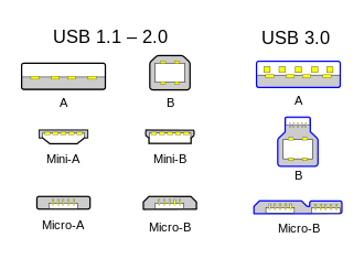
Comparison of legacy USB connector plugs, omitting the current standard
Type-C plugs
 Unlike other data buses (such as Ethernet), USB connections are directed; a host
device has "downstream" facing ports that connect to the "upstream" facing ports
of devices. Only downstream facing ports provide power; this topology was
chosen to easily prevent electrical overloads and damaged equipment. Thus, USB
cables have different ends: A and B, with different physical connectors for each.
Each format has a plug and receptacle defined for each of the A and B ends.
A USB cable, by definition, has a plug on each end—one A (or C) and one B
(or C)—and the corresponding receptacle is usually on a computer or
electronic device. The mini and micro formats may connect to an AB
receptacle, which accepts either an A or a B plug, that plug determining the
behavior of the receptacle.
The three sizes of USB connectors are the default, or standard, format
intended for desktop or portable equipment, the mini intended for mobile
equipment, which was deprecated when it was replaced by the thinner micro
size, all of which were deprecated in USB 3.2 in favor of Type-C. There are
five speeds for USB data transfer: Low Speed, Full Speed, High Speed (from
version 2.0 of the specification), SuperSpeed (from version 3.0), and
SuperSpeed+ (from version 3.1). The modes have differing hardware and
cabling requirements. USB devices have some choice of implemented modes, and
USB version is not a reliable statement of implemented modes. Modes are
identified by their names and icons, and the specification suggests that
plugs and receptacles be color-coded (SuperSpeed is identified by blue).
Unlike other data buses (such as Ethernet), USB connections are directed; a host
device has "downstream" facing ports that connect to the "upstream" facing ports
of devices. Only downstream facing ports provide power; this topology was
chosen to easily prevent electrical overloads and damaged equipment. Thus, USB
cables have different ends: A and B, with different physical connectors for each.
Each format has a plug and receptacle defined for each of the A and B ends.
A USB cable, by definition, has a plug on each end—one A (or C) and one B
(or C)—and the corresponding receptacle is usually on a computer or
electronic device. The mini and micro formats may connect to an AB
receptacle, which accepts either an A or a B plug, that plug determining the
behavior of the receptacle.
The three sizes of USB connectors are the default, or standard, format
intended for desktop or portable equipment, the mini intended for mobile
equipment, which was deprecated when it was replaced by the thinner micro
size, all of which were deprecated in USB 3.2 in favor of Type-C. There are
five speeds for USB data transfer: Low Speed, Full Speed, High Speed (from
version 2.0 of the specification), SuperSpeed (from version 3.0), and
SuperSpeed+ (from version 3.1). The modes have differing hardware and
cabling requirements. USB devices have some choice of implemented modes, and
USB version is not a reliable statement of implemented modes. Modes are
identified by their names and icons, and the specification suggests that
plugs and receptacles be color-coded (SuperSpeed is identified by blue).
Connector properties
Non-standard "USB extension cable", plug on the left, receptacle on the right.
(USB does not allow extension cables. Non-standard cables may work but cannot
be presumed reliable.)
The connectors the USB committee specifies support a number of USB's underlying
goals, and reflect lessons learned from the many connectors the computer
industry has used. The connector mounted on the host or device is called the
receptacle, and the connector attached to the cable is called the plug.[1] The
official USB specification documents also periodically define the term male to
represent the plug, and female to represent the receptacle, though these uses
are inconsistent with established definitions of connector gender.[2]
By design, it is difficult to insert a USB plug into its receptacle
incorrectly. The USB specification requires that the cable plug and
receptacle be marked so the user can recognize the proper orientation.[1]
The USB-C plug however is reversible. USB cables and small USB devices are
held in place by the gripping force from the receptacle, with no screws,
clips, or thumb-turns as other connectors use.
The different A and B plugs prevent accidentally connecting two power sources.
However, some of this directed topology is lost with the advent of
multi-purpose USB connections (such as USB On-The-Go in smartphones, and
USB-powered Wi-Fi routers), which require A-to-A, B-to-B, and sometimes
Y/splitter cables. See the USB On-The-Go connectors section below for a more
detailed summary description.
There are so-called cables with A plugs on both ends, which may be valid if
the "cable" includes, for example, a USB host-to-host transfer device with two
ports.[3] This is, by definition, a device with two logical B ports, each
with a captive cable, not a cable with two A ends.
Durability
The standard connectors were designed to be more robust than many past
connectors. This is because USB is hot-swappable, and the connectors would
be used more frequently, and perhaps with less care, than previous connectors.
Standard USB has a minimum rated lifetime of 1,500 cycles of insertion and
removal,[4] the Mini-USB receptacle increased this to 5,000 cycles,[4] and
the newer Micro-USB[4] and USB-C receptacles are both designed for a minimum
rated lifetime of 10,000 cycles of insertion and removal.[5] To accomplish
this, a locking device was added and the leaf-spring was moved from the jack
to the plug, so that the most-stressed part is on the cable side of the
connection. This change was made so that the connector on the less expensive
cable would bear the most wear.[4]
In standard USB, the electrical contacts in a USB connector are protected by
an adjacent plastic tongue, and the entire connecting assembly is usually
protected by an enclosing metal shell.[4]
The shell on the plug makes contact with the receptacle before any of the
internal pins. The shell is typically grounded, to dissipate static
electricity and to shield the wires within the connector.
Compatibility
The USB standard specifies tolerances for compliant USB connectors to
minimize physical incompatibilities in connectors from different vendors.
The USB specification also defines limits to the size of a connecting
device
in the area around its plug, so that adjacent ports are not blocked.
Compliant devices must either fit within the size restrictions or support a
compliant extension cable that does.
Pinouts
See also: USB 3.0 § Pinouts
USB 2.0 uses two wires for power (VBUS and GND), and two for differential
serial data signals. Mini and micro connectors have their GND connections
moved from pin #4 to pin #5, while their pin #4 serves as an ID pin for the
On-The-Go host/client identification.[6]
USB 3.0 provides two additional differential pairs (four wires, SSTx+,
SSTx−, SSRx+ and SSRx−), providing full-duplex data transfers at
SuperSpeed, which makes it similar to Serial ATA or single-lane PCI
Express.
|
|
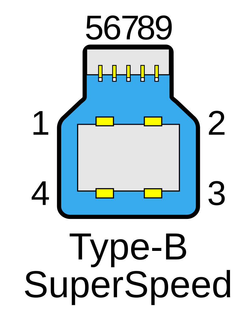
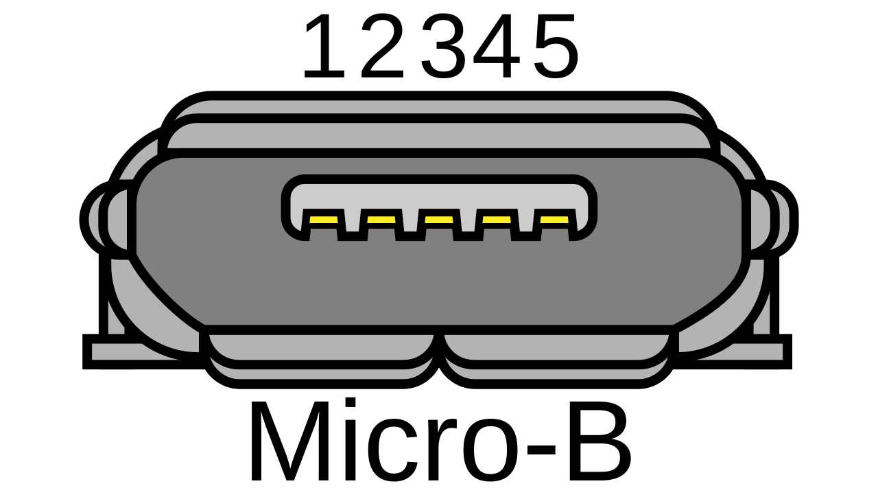
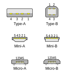 Standard, Mini-, and Micro-USB plugs shown end-on, not to scale. Light
areas represent cavities. The plugs are pictured with USB logo to the top.[7]
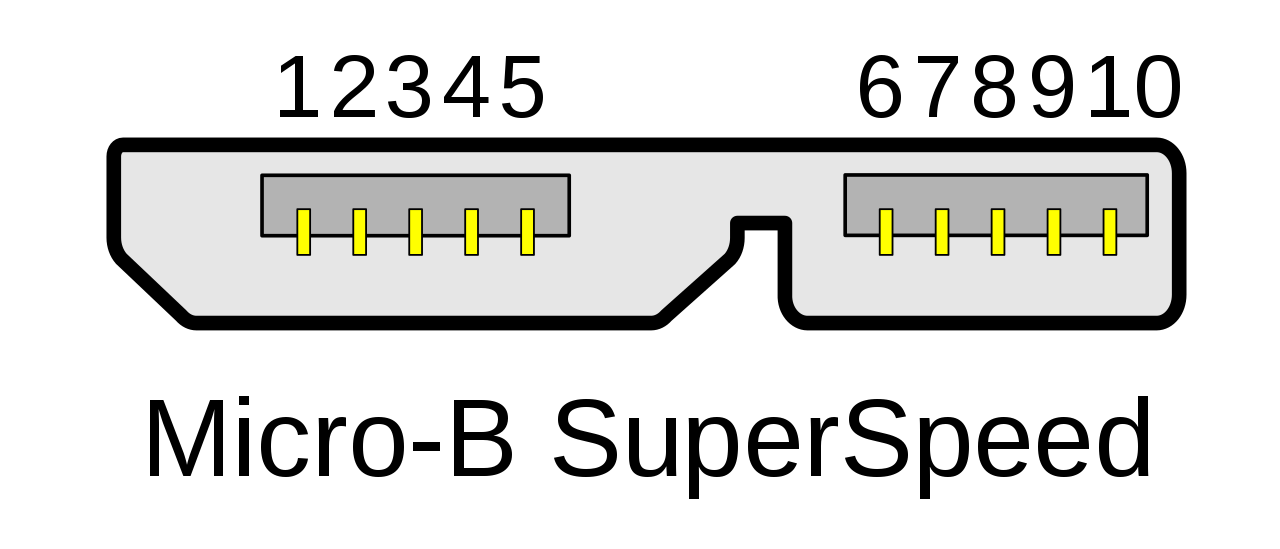
Micro-B SuperSpeed plug
Standard, Mini-, and Micro-USB plugs shown end-on, not to scale. Light
areas represent cavities. The plugs are pictured with USB logo to the top.[7]
Micro-B SuperSpeed plug
|
- Power (VBUS, 5 V)
- Data− (D−)
- Data+ (D+)
- ID (On-The-Go)
- GND
- SuperSpeed transmit− (SSTx−)
- SuperSpeed transmit+ (SSTx+)
- GND
- SuperSpeed receive− (SSRx−)
- SuperSpeed receive+ (SSRx+)
|
Type-A and -B pinout
| Pin
| Name
| Wire Color (a)
| Descr
|
| 1 | VBUS | Red or | Orange | +5 V
|
| 2 | D− | White or | Gold | Data−
|
| 3 | D+ | Green | Data+
|
| 4 | GND | Black or | Blue | Ground
|
Mini/Micro-A and -B pinout
| Pin
| Name
| Wire Color [a]
| Descr
|
| 1 | VBUS | Red | +5 V
|
| 2 | D− | White | Data−
|
| 3 | D+ | Green | Data+
|
| 4 | ID | No wire | On-The-Go ID distinguishes cable ends:
- "A" plug (host): connected to GND
- "B" plug (device): not connected
|
| 5 | GND | Black | Signal ground
|
In some sources D+ and D− are erroneously swapped.
Colors
| |
|
Usual USB color-coding
|
|
| Color
| Location
| Description
|
| | Black or white | Receptacles and plugs | Type-A or Type-B
| | | Blue (Pantone 300C) | Receptacles and plugs | Type-A or Type-B, SuperSpeed
| | | Teal blue | Receptacles and plugs | Type-A or Type-B, SuperSpeed+
| | | Green | Receptacles and plugs | Type-A or Type-B, Qualcomm Quick Charge (QC)
| | | Purple | Plugs only | Type-A or Type-C, Huawei SuperCharge
| | | | Yellow or red | Receptacles only
High-current or sleep-and-charge
| | | Orange | Receptacles only | High-retention connector, mostly used on
industrial hardware
|
|
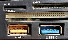 A yellow charge-only "USB" Type-A receptacle and a USB 3.0 Type-A
receptacle,
both upside-down, on a front panel with card reader
A yellow charge-only "USB" Type-A receptacle and a USB 3.0 Type-A
receptacle,
both upside-down, on a front panel with card reader
 A blue Standard-A USB receptacle without USB 3.0 contacts fitted
|
USB ports and connectors are often color-coded to distinguish their
different functions and USB versions. These colors are not part of the USB
specification and can vary between manufacturers; for example, the USB 3.0
specification mandates appropriate color-coding while it only recommends
blue inserts for Standard-A USB 3.0 connectors and plugs.[8]
Connector types
USB connector types multiplied as the specification progressed. The
original
USB specification detailed standard-A and standard-B plugs and receptacles.
The connectors were different so that users could not connect one computer
receptacle to another. The data pins in the standard plugs are recessed
compared to the power pins so that the device can power up before
establishing a data connection. Some devices operate in different modes
depending on whether the data connection is made. Charging docks supply
power and do not include a host device or data pins, allowing any capable
USB device to charge or operate from a standard USB cable. Charging cables
provide power connections, but not data. In a charge-only cable, the data
wires are shorted at the device end, otherwise, the device may reject the
charger as unsuitable.
Standard connectors
|
|
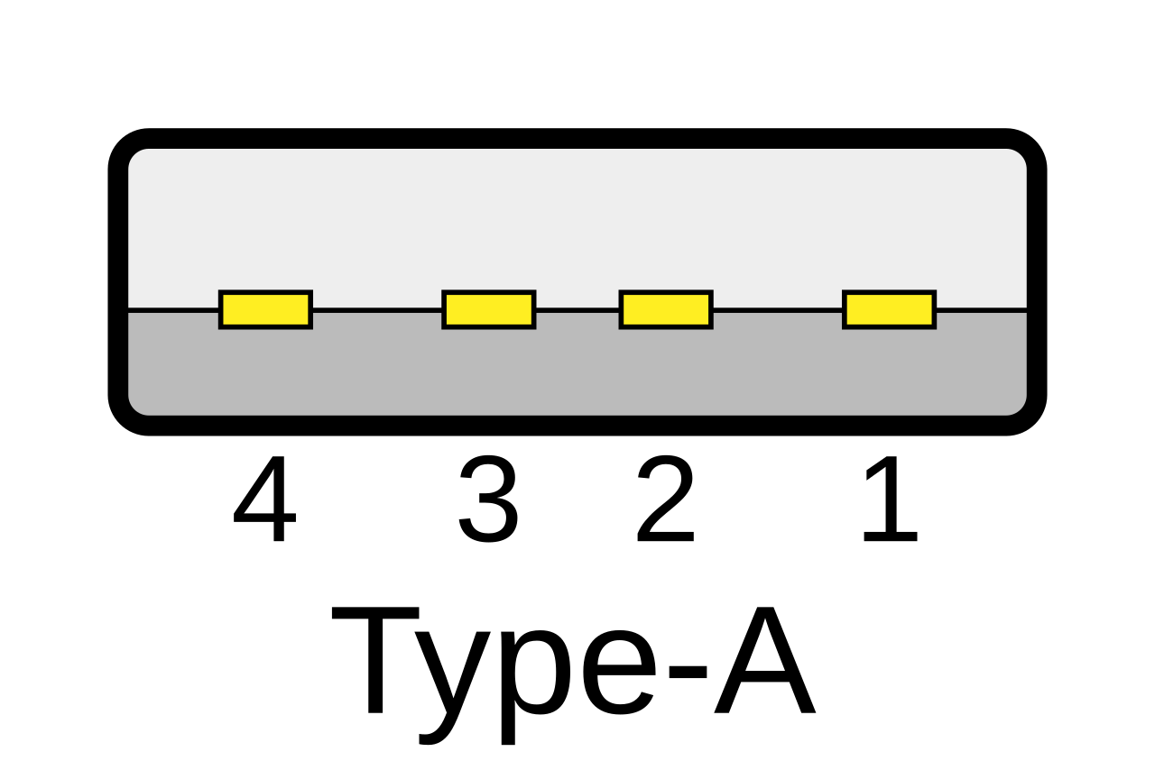
- The Type-A plug. This plug has an elongated rectangular cross-section,
inserts into a Type-A receptacle on a downstream port on a USB host or hub,
and carries both power and data. Captive cables on USB devices, such as
keyboards or mice, terminate with a Type-A plug.
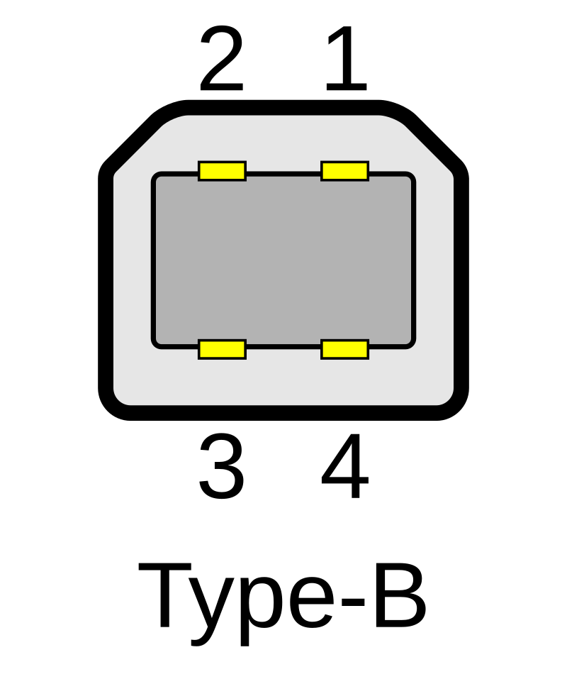
- The Type-B plug: This plug has a near square cross-section with the top
exterior corners beveled. As part of a removable cable, it inserts into an
upstream port on a device, such as a printer. On some devices, the Type-B
receptacle has no data connections, being used solely for accepting power
from the upstream device. This two-connector-type scheme (A/B) prevents a
user from accidentally creating a loop.[9][10]
|
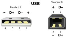
Pin configuration of Type-A and Type-B plugs viewed end-on
|
The maximum allowed cross-section of the overmold boot (which is part of the
connector used for its handling) is 16 by 8 mm (0.63 by 0.31 in) for the
Standard-A plug type, while for the Type-B it is 11.5 by 10.5 mm
(0.45 by 0.41 in).[2]
Mini connectors
|
|
|
Mini-USB connectors were introduced together with USB 2.0 in April 2000,
for
use with smaller devices such as digital cameras, smartphones, and tablet
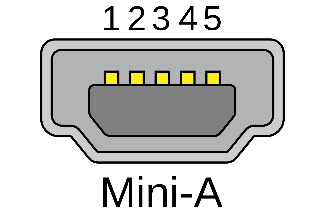
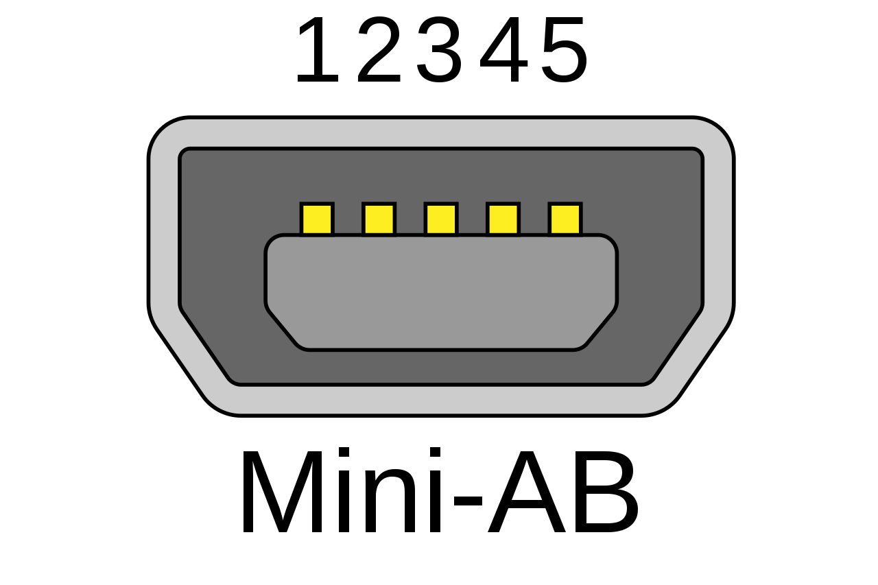
computers. The Mini-A connector and the Mini-AB receptacle connector have
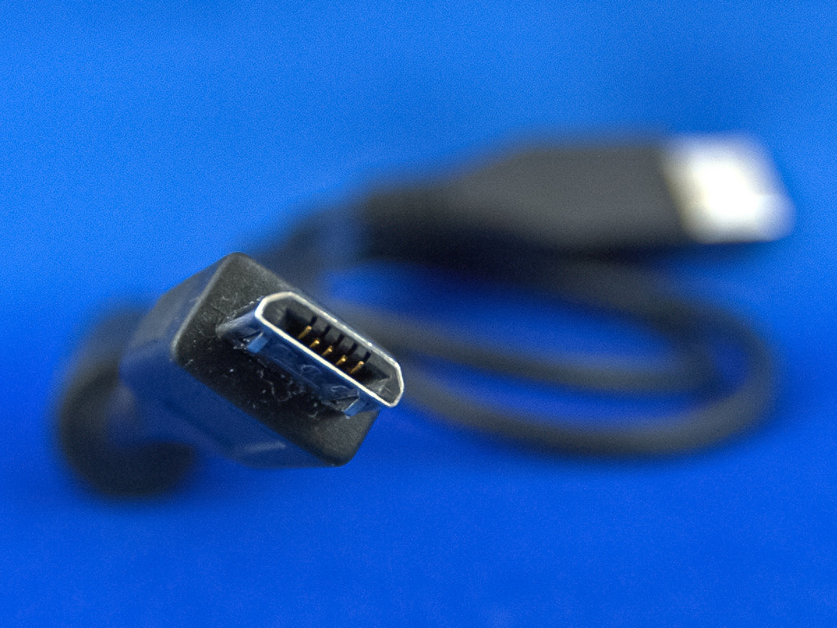
been deprecated since May 2007.[11] Mini-B connectors are still supported,
but are not On-The-Go-compliant;[12] the Mini-B USB connector was standard
for transferring data to and from the early smartphones and PDAs. Both Mini
-A and Mini-B plugs are approximately 3 by 7 mm (0.12 by 0.28 in). The Mini
-AB receptacle accepts either a Mini-A or Mini-B plug.
|
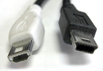
Mini-A (left) and Mini-B (right) plugs
|
Micro connectors
| |
|
|
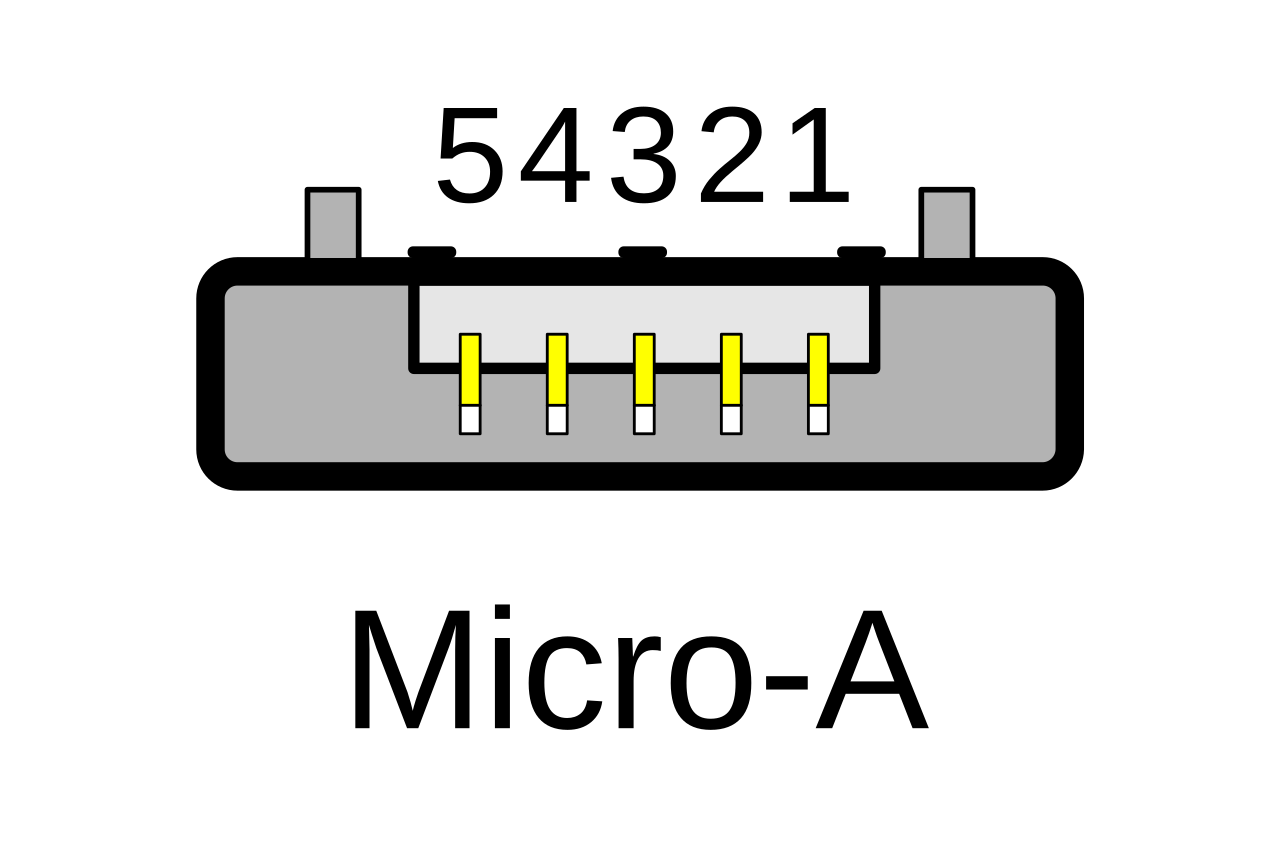
Micro-USB connectors, which were announced by the USB-IF on January 4,
2007,[13][14] have a similar width to Mini-USB, but approximately half the
thickness, enabling their integration into thinner portable devices. The
Micro-A connector is 6.85 by 1.8 mm (0.270 by 0.071 in) with a maximum
overmold boot size of 11.7 by 8.5 mm (0.46 by 0.33 in), while the Micro-B
connector is 6.85 by 1.8 mm (0.270 by 0.071 in) with a maximum overmold
size of 10.6 by 8.5 mm (0.42 by 0.33 in).[7]
|
 Micro-A
plug
Micro-A
plug
|
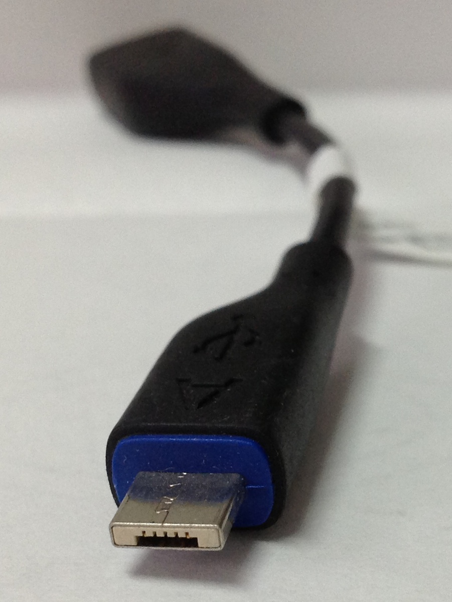
 Micro-B
plug
Micro-B
plug
|
The thinner Micro-USB connectors were intended to replace the Mini
connectors in devices manufactured since May 2007, including smartphones,
personal digital assistants, and cameras.[15]
The Micro plug design is rated for at least 10,000 connect-disconnect
cycles, which is more than the Mini plug design.[13][16] The Micro
connector
is also designed to reduce the mechanical wear on the device; instead, the
easier-to-replace cable is designed to bear the mechanical wear of
connection and disconnection. The Universal Serial Bus Micro-USB Cables and
Connectors Specification details the mechanical characteristics of Micro-A
plugs, Micro-AB receptacles (which accept both Micro-A and Micro-B plugs),
Double-Sided Micro USB, and Micro-B plugs and receptacles,[16] along with a
Standard-A receptacle to a Micro-A plug adapter.
OMTP standard
Micro-USB was endorsed as the standard connector for data and power on
mobile devices by the cellular phone carrier group Open Mobile Terminal
Platform (OMTP) in 2007.[17]
Micro-USB was embraced as the "Universal Charging Solution" by the
International
Telecommunication Union
(ITU) in October 2009.[18]
In Europe, micro-USB became the defined common external power supply (EPS)
for use with smartphones sold in the EU,[19] and 14 of the world's largest
mobile phone manufacturers signed the EU's common EPS Memorandum of
Understanding (MoU).[20][21] Apple, one of the original MoU signers, makes
Micro-USB adapters available—as permitted in the Common EPS MoU—for its
iPhones equipped with Apple's proprietary 30-pin dock connector or (later)
Lightning connector.[22][23] according to the CEN, CENELEC, and ETSI.
USB 3.x connectors and backward compatibility
See also: USB 3.0 § Connectors
|
|
|
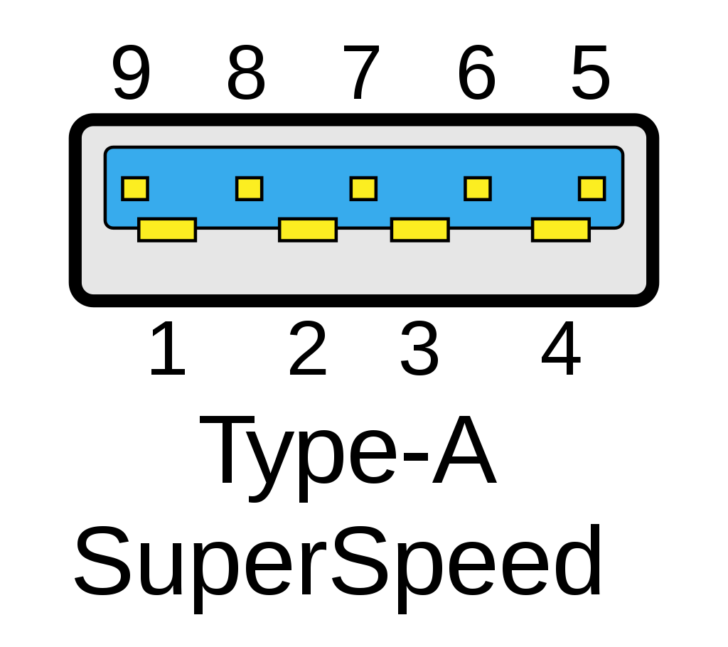
USB 3.0 introduced Type-A SuperSpeed plugs and receptacles as well as micro -sized
Type-B SuperSpeed plugs and receptacles. The 3.0 receptacles are
backward-compatible with the corresponding pre-3.0 plugs.
USB 3.x and USB 1.x Type-A plugs and receptacles are designed to
interoperate. To achieve USB 3.0's SuperSpeed (and SuperSpeed+ for USB 3.1
Gen 2), 5 extra pins are added to the unused area of the original 4 pin USB
1.0 design, making USB 3.0 Type-A plugs and receptacles backward compatible
to those of USB 1.0.
|
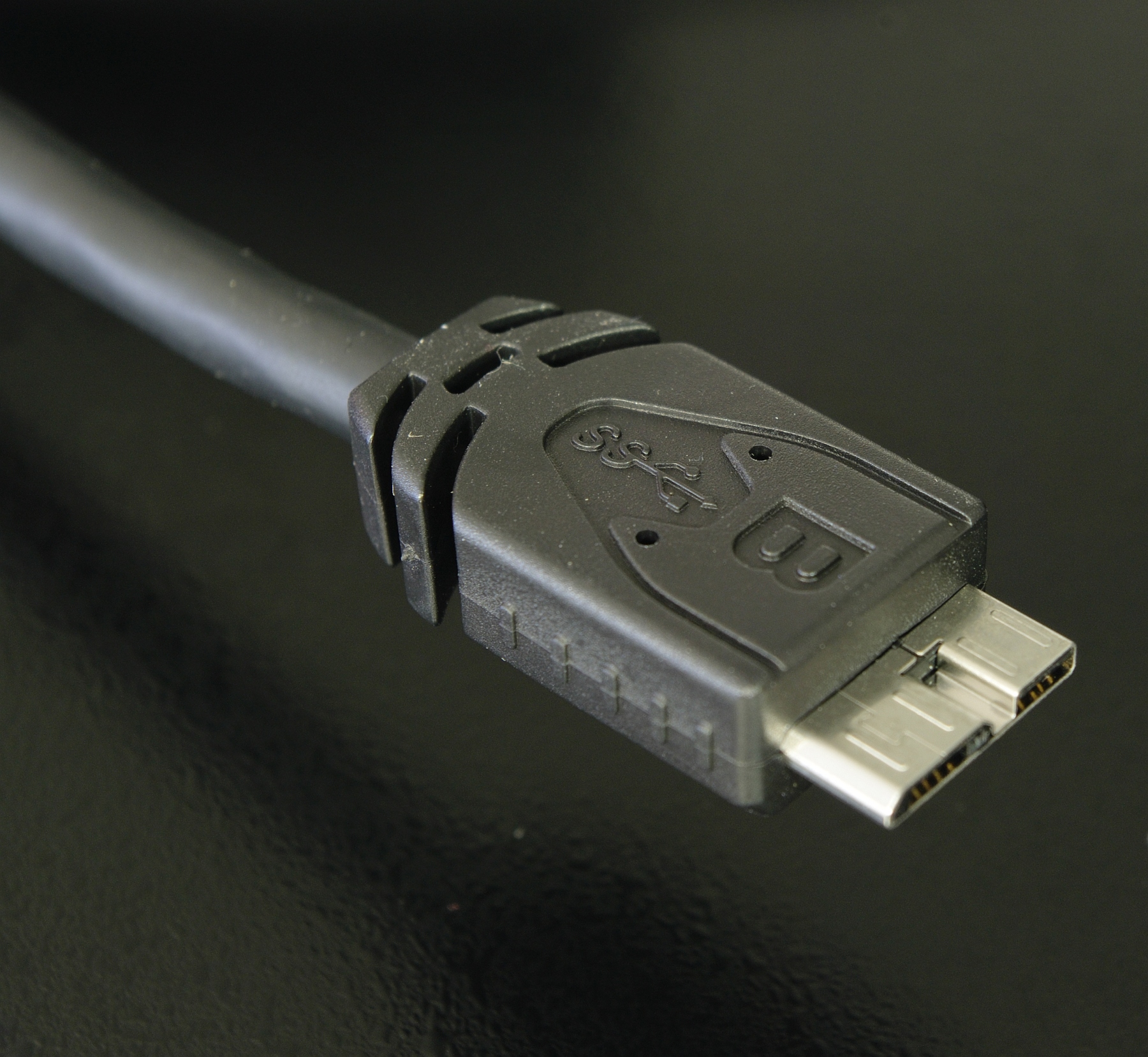
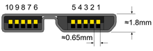
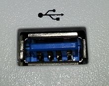
USB 3.0 Micro-B SuperSpeed plug
|
On the device side, a modified Micro-B plug (Micro-B SuperSpeed) is used to
cater for the five additional pins required to achieve the USB 3.0 features
(USB-C plug can also be used). The USB 3.0 Micro-B plug effectively consists
of a standard USB 2.0 Micro-B cable plug, with an additional 5 pins plug "stacked"
to the side of it. In this way, cables with smaller 5 pin USB 2.0 Micro-B plugs
can be plugged into devices with 10 contact USB 3.0 Micro-B receptacles and
achieve backward compatibility.
USB cables exist with various combinations of plugs on each end of the
cable, as displayed below in the USB cables matrix.
USB On-The-Go connectors
Main article: USB On-The-Go
|
|
|
USB On-The-Go (OTG) introduces the concept of a device performing both host
and device roles. All current OTG devices are required to have one, and only
one, USB connector: a Micro-AB receptacle. (In the past, before the development
of Micro-USB, On-The-Go devices used Mini-AB receptacles.)
|
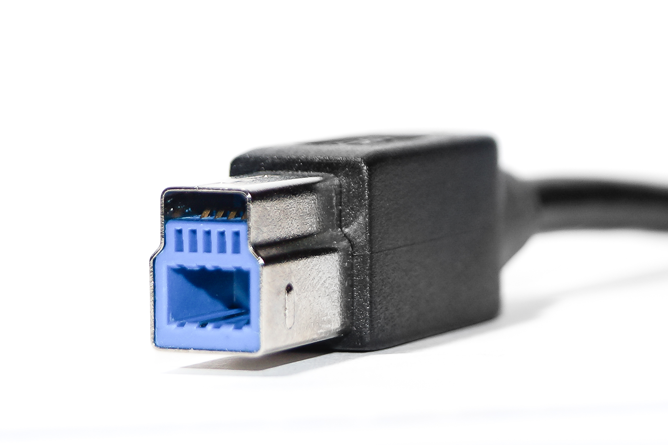 USB 3.0 Standard-B plug
|
The Micro-AB receptacle is capable of accepting Micro-A and Micro-B plugs,
attached to any of the legal cables and adapters as defined in revision 1.01
of the Micro-USB specification.
To enable Type-AB receptacles to distinguish which end of a cable is plugged
in, plugs have an "ID" pin in addition to the four contacts in standard-size USB
connectors. This ID pin is connected to GND in Type-A plugs, and left
unconnected in Type-B plugs. Typically, a pull-up resistor in the device is
used to detect the presence or absence of an ID connection.
The OTG device with the A-plug inserted is called the A-device and is
responsible for powering the USB interface when required, and by default
assumes the role of host. The OTG device with the B-plug inserted is called
the B-device and by default assumes the role of peripheral. An OTG device
with no plug inserted defaults to acting as a B-device. If an application on
the B-device requires the role of host, then the Host Negotiation Protocol
(HNP) is used to temporarily transfer the host role to the B-device.
OTG devices attached either to a peripheral-only B-device or a
standard/embedded host have their role fixed by the cable, since in these
scenarios it is only possible to attach the cable one way.[citation needed]
USB-C
Main article: USB-C
|
|
|
The USB-C connector supersedes all earlier USB connectors and the Mini
DisplayPort connector. It is used for all USB protocols and for Thunderbolt
(3 and later), DisplayPort (1.2 and later), and others. Developed at
roughly
the same time as the USB 3.1 specification, but distinct from it, the USB-C
Specification 1.0 was finalized in August 2014[24] and defines a new small
reversible-plug connector for USB devices.[25] The USB-C plug connects to
both hosts and devices, replacing various Type-A and Type-B connectors and
cables with a standard meant to be future-proof.[24][26]
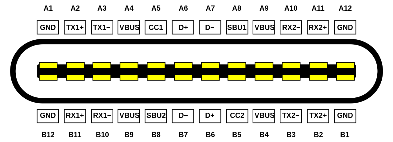
The 24-pin double-sided connector provides four power–ground pairs, two
Differential pairs for USB 2.0 data
(though only one pair is implemented in a USB-C cable), four pairs for
|
The USB-C plug
|
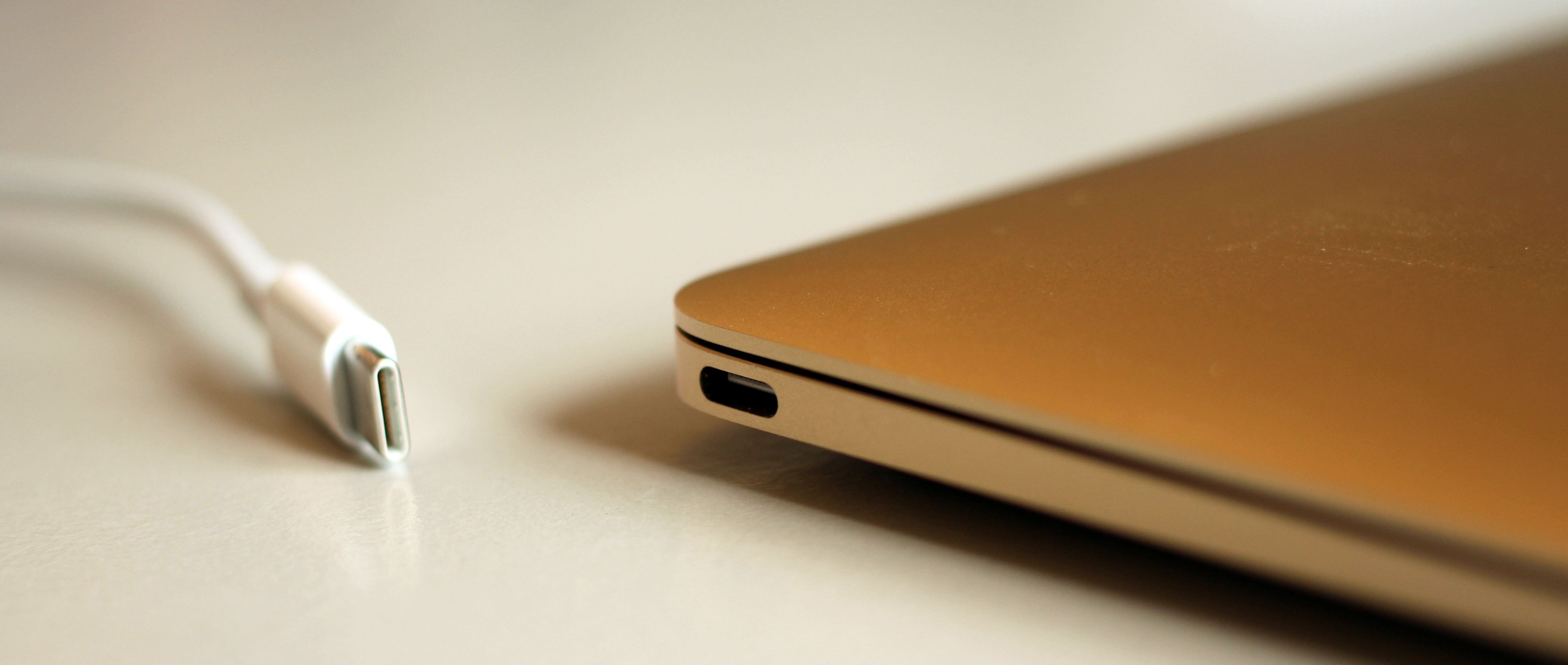 USB cable with a USB-C plug and a USB-C port on a notebook computer
|
SuperSpeed data bus (only two pairs are used in USB 3.1 mode), two "sideband use"
pins, VCONN +5 V power for active cables, and a configuration pin for cable
orientation detection and dedicated biphase mark code (BMC) configuration data
channel.[27][28] Type-A and Type-B adaptors and cables are required for older
hosts and devices to plug into USB-C hosts and devices. Adapters and cables with
a USB-C receptacle are not allowed.[29]
Full-featured USB-C 3.1 cables are electronically marked cables that contain a
full set of wires and a chip with an ID function based on the configuration data
channel and vendor-defined messages (VDMs) from the USB Power Delivery 2.0
specification. USB-C devices also support power currents of 1.5 A and 3.0 A over
the 5 V power bus in addition to baseline 900 mA; devices can either negotiate
increased USB current through the configuration line or they can support the
full Power Delivery specification using both BMC-coded configuration line and
legacy BFSK-coded VBUS line.[citation needed] Full-Featured USB Type-C devices
are a mechanic prerequisite for multi-lane operation (USB 3.2 Gen 1x2, USB 3.2
Gen 2x2, USB4 2x2, USB4 3x2, USB Gen 4 Asymmetric).[30]
Host and device interface receptacles
USB plugs fit one receptacle with notable exceptions for USB On-The-Go "AB"
support and the general backward compatibility of USB 3.0 as shown.
USB connector mating table (images not to scale)
| Plug
Receptacle
| USB A
| USB 3.0 A SS
| USB B
| USB 3.0 B SS
| USB Mini-A
| USB Mini-B
| USB Micro-A1
| USB Micro-B
| USB 3.0 Micro-B
| USB-C
|
| USB A
| Yes | Only non-SuperSpeed | No | No | No | No | No | No | No | No
|
| USB 3.0 A SS
| Only non-
SuperSpeed | Yes | No | No | No | No | No | No | No | No
|
| USB B
| No | No | Yes | No | No | No | No | No | No | No
|
| USB 3.0 B SS
| No | No | Only non-
SuperSpeed | Yes | No | No | No | No | No | No
|
| USB Mini-A
| No | No | No | No | Yes | No | No | No | No | No
|
| USB Mini-AB
| No | No | No | No | Deprecated | Deprecated | No | No | No | No
|
| USB Mini-B
| No | No | No | No | No | Yes | No | No | No | No
|
| USB Micro-AB
| No | No | No | No | No | No | Yes | Yes | No | No
|
| USB Micro-B
| No | No | No | No | No | No | No | Yes | No | No
|
| USB 3.0 Micro-B SS
| No | No | No | No | No | No | No | Only non-
SuperSpeed | Yes | No
|
| USB-C
| No | No | No | No | No | No | No | No | No | Yes
|
| ^1 No corresponding Micro-A receptacle was ever designed.
|
USB cables table Plugs, each end USB A
USB Mini-A
USB Micro-A
USB B
USB Mini-B
USB Micro-B
USB 3.0 Micro-B
USB-C
USB A
Proprietary,
hazardous Proprietary,
hazardous Proprietary,
hazardous Yes Yes Yes Yes Yes
USB Mini-A
Proprietary,
hazardous No No Deprecated Deprecated Non-
standard No No
USB Micro-A
Proprietary,
hazardous No No Non-
standard Non-
standard Yes No No
USB B
Yes Deprecated Non-
standard No No No No Yes
USB Mini-B
Yes Deprecated Non-
standard No OTG non-
standard OTG non-
standard No Yes
USB Micro-B
Yes Non-
standard Yes No OTG non-
standard OTG non-
standard No Yes
USB 3.0 Micro-B
Yes No No No No No OTG non-
standard Yes
USB-C
Yes No No Yes Yes Yes Yes Yes
Proprietary, hazardous
Existing for specific proprietary purposes, not inter-operable with USB-IF
compliant equipment and possibly damaging to both devices when plugged in.
In
addition to the above cable assemblies comprising two plugs, an "adapter"
cable
with a Micro-A plug and a standard-A receptacle is compliant with USB
specifications.[7] Other combinations of connectors are not compliant.
There do exist A-to-A assemblies, referred to as cables (such as the Easy
Transfer Cable); however, these have a pair of USB devices in the middle,
making
them more than just cables.
Non-standard
The USB standards do not exhaustively list all combinations with one
Type-A
and one Type-B connector, however, most such cables have good chances of
working.
OTG non-standard
Commonly available "OTG" cables that address widespread misuse of Micro-B
and
Mini-B receptacles for OTG devices, e.g. smartphones (as opposed to
Micro-AB and
Mini-AB, which accept either plug.) While not compliant with the USB
standards,
these cables at least do not provide a device damage hazard since Type-B
ports
on devices are unpowered by default.[31]
Deprecated
Some older devices and cables with Mini-A connectors have been
certified by
USB-IF. The Mini-A connector is obsolete: no new Mini-A connectors and
neither
Mini-A nor Mini-AB receptacles will be certified.[11]
Note: Mini-B is not deprecated, although it is less and less used since
the
arrival of Micro-B. Micro-A and Micro-B have one more contact than
Standard-A
and Standard-B in order for hardware with a Micro-AB receptacle to discern
Micro-A from Micro-B and behave as a host or device accordingly.
Proprietary connectors and formats
Manufacturers of personal electronic devices might not include a USB
standard
connector on their product for technical or marketing reasons.[32] E.g.
Olympus
has been using a special cable called CB-USB8 one end of which has a
special
contact. Some manufacturers provide proprietary cables, such as Lightning,
that
permit their devices to physically connect to a USB standard port. Full
functionality of proprietary ports and cables with USB standard ports is
not
assured; for example, some devices only use the USB connection for battery
charging and do not implement any data transfer functions.[33]
Cabling
A USB twisted pair, in which the Data+ and Data− conductors are twisted
together
in a double helix. The wires are enclosed in a further layer of shielding.
The D± signals used by low, full, and high speed are carried over a
twisted pair
(typically unshielded) to reduce noise and crosstalk. SuperSpeed uses
separate
transmit and receive differential pairs, which additionally require
shielding
(typically, shielded twisted pair but twinax is also mentioned by the
specification). Thus, to support SuperSpeed data transmission, cables
contain
twice as many wires and are larger in diameter.[34]
The USB 1.1 standard specifies that a standard cable can have a maximum
length
of 5 meters (16 ft 5 in) with devices operating at full speed (12 Mbit/s),
and a
maximum length of 3 meters (9 ft 10 in) with devices operating at low
speed
(1.5 Mbit/s).[35][36][37]
USB 2.0 provides for a maximum cable length of 5 meters (16 ft 5 in) for
devices
running at high speed (480 Mbit/s). The primary reason for this limit is
the
maximum allowed round-trip delay of about 1.5 μs. If USB host commands are
unanswered by the USB device within the allowed time, the host considers
the
command lost. When adding USB device response time, delays from the maximum
number of hubs added to the delays from connecting cables, the maximum
acceptable delay per cable amounts to 26 ns.[37] The USB 2.0 specification
requires that cable delay be less than 5.2 ns/m (1.6 ns/ft, 192000 km/s),
which
is close to the maximum achievable transmission speed for standard copper
wire.
The USB 3.0 standard does not directly specify a maximum cable length,
requiring
only that all cables meet an electrical specification: for copper cabling
with
AWG 26 wires the maximum practical length is 3 meters (9 ft 10 in).[38]
Power
See also: USB hub § Power
Upstream USB connectors supply power at a nominal 5 V DC via the V_BUS pin
to
downstream USB devices.
Voltage tolerance and limits
Worst-case voltage drop topology of a USB 2.0 host to low-power device
chain, at
steady state
The tolerance on V_BUS at an upstream (or host) connector was originally
±5%
(i.e. could lie anywhere in the range 4.75 V to 5.25 V). With the release
of the USB Type-C specification in 2014 and its 3 A power capability, the
USB-IF elected to increase the upper voltage limit to 5.5 V to combat
voltage droop at higher currents.[39] The USB 2.0 specification (and
therefore implicitly also the USB 3.x specifications) was also updated to
reflect this change at that time.[40] A number of extensions to the USB
Specifications have progressively further increased the maximum allowable
V_BUS voltage: starting with 6.0V with USB BC 1.2,[41] to 21.5 V with USB
PD 2.0[42] and 50.9 V with USB PD 3.1,[42] while still maintaining
backwards compatibility with USB 2.0 by requiring various forms of
handshake before increasing the nominal voltage above 5 V.
USB PD continues the use of the bilateral 5% tolerance, with allowable
voltages of PDO ±5% ±0.5 V (eg. for a PDO of 9.0 V, the maximum and
minimum limits are 9.95 V and 8.05 V, respectively).[42]
There are several minimum allowable voltages defined at different locations
within a chain of connectors, hubs, and cables between an upstream host
(providing the power) and a downstream device (consuming the power). To
allow for voltage drops, the voltage at the host port, hub port, and
device are specified to be at least 4.75 V, 4.4 V, and 4.35 V respectively
by USB 2.0 for low-power devices,[a] but must be at least 4.75 V at all
locations for high-power[b] devices (however, high-power devices are
required to operate as a low-powered device so that they may be detected
and enumerated if connected to a low-power upstream port). The USB 3.x
specifications require that all devices must operate down to 4.00 V at the
device port.
Unlike USB 2.0 and USB 3.2, USB4 does not define its own VBUS-based power
model. Power for USB4 operation is established and managed as defined in
the USB Type-C Specification and the USB PD Specification.
Low-power devices are those which draw less than 1 unit load. 1 unit load
is 100 mA for USB 2.0
High-power devices in USB 2.0 are those draw more than one unit load
(up to a maximum of 5 unit loads). 1 unit load is 100mA.
Worst-case voltage drop topology of a USB 3.x host to device chain, at
steady state. Note that under transient conditions the supply at the
device can momentarily drop from 4.0 V to 3.67 V.
Allowable current draw
USB power standards Specification Current Voltage Power (max.)
Low-power device 100 mA 5 V 0.50 W
Low-power SuperSpeed (USB 3.0) device 150 mA 5 V 0.75 W
High-power device 500 mA[a] 5 V 2.5 W
High-power SuperSpeed (USB 3.0) device 900 mA[b] 5 V 4.5 W
Multi-lane SuperSpeed (USB 3.2 Gen x2) device 1.5 A[c] 5 V 7.5 W
Battery Charging (BC) 1.2 1.5 A 5 V 7.5 W
USB-C (multi-lane) 1.5 A[c] 5 V 7.5 W
3 A 5 V 15 W
Power Delivery 1.0/2.0/3.0 Type-C 5 A[d] 20 V 100 W
Power Delivery 3.1 Type-C 5 A[d] 48 V[e] 240 W
Up to 5 unit loads; with non-SuperSpeed devices, one unit load is 100 mA.
Up to 6 unit loads; with SuperSpeed devices, one unit load is 150 mA.
Up to 6 unit loads; with multi-lane devices, one unit load is 250 mA.
>3 A (>60 W) operation requires an electronically marked cable rated at 5
A.
>20 V (>60 W) operation requires an electronically marked Extended
Power Range (EPR) cable.
The limit to device power draw is stated in terms of a unit load which is
100 mA for USB 2.0, or 150 mA for SuperSpeed (i.e. USB 3.x) devices.
Low-power devices may draw at most 1 unit load, and all devices must act
as low-power devices before they are configured. A high-powered device
must be configured, after which it may draw up to 5 unit loads (500 mA),
or 6 unit loads (900 mA) for SuperSpeed devices, as specified in its
configuration because the maximum power may not always be available from
the upstream port.[43][44][45][46]
A bus-powered hub is a high-power device providing low-power ports. It
draws 1 unit load for the hub controller and 1 unit load for each of at
most 4 ports. The hub may also have some non-removable functions in place
of ports. A self-powered hub is a device that provides high-power ports by
supplementing the power supply from the host with its own external supply.
Optionally, the hub controller may draw power for its operation as a
low-power device, but all high-power ports must draw from the hub's
self-power.
Where devices (for example, high-speed disk drives) require more power than
a high-power device can draw,[47] they function erratically, if at all,
from bus power of a single port. USB provides for these devices as being
self-powered. However, such devices may come with a Y-shaped cable that
has two USB plugs (one for power and data, the other for only power), so
as to draw power as two devices.[48] Such a cable is non-standard, with
the USB compliance specification stating that "use of a 'Y' cable (a cable
with two A-plugs) is prohibited on any USB peripheral", meaning that "if a
USB peripheral
requires more power than allowed by the USB specification to which it is
designed, then it must be self-powered."[49]
USB battery charging
USB Battery Charging (BC) defines a charging port, which may be a charging
downstream port (CDP), with data, or a dedicated charging port (DCP)
without data. Dedicated charging ports can be found on USB power adapters
to run attached devices and battery packs. Charging ports on a host with
both kinds will be labeled.[50]
The charging device identifies a charging port by non-data signaling on the
D+ and D− terminals. A dedicated charging port places a resistance not
exceeding 200 Ω across the D+ and D− terminals.[50]: § 1.4.7; table
5-3
Per the base specification, any device attached to a standard downstream
port (SDP) must initially be a low-power device, with high-power mode
contingent on later USB configuration by the host. Charging ports,
however, can immediately supply between 0.5 and 1.5 A of current. The
charging port must not apply current limiting below 0.5 A, and must not
shut down below 1.5 A or before the voltage drops to 2 V.[50]
Since these currents are larger than in the original standard, the extra
voltage drop in the cable reduces noise margins, causing problems with
High Speed signaling. Battery Charging Specification 1.1 specifies that
charging devices must dynamically limit bus power current draw during High
Speed signaling;[51] 1.2 specifies that charging devices and ports must be
designed to tolerate the higher ground voltage difference in High Speed
signaling.
Revision 1.2 of the specification was released in 2010. It made several
changes, and increased limits including allowing 1.5 A on charging
downstream ports for unconfigured devices—allowing High Speed
communication while having a current up to 1.5 A. Also, support was
removed for charging port detection via resistive mechanisms.[52]
Before the Battery Charging Specification was defined, there was no
standardized way for the portable device to inquire how much current was
available. For example, Apple's iPod and iPhone chargers indicate the
available current by voltages on the D− and D+ lines. When D+ = D− =
2.0 V, the device may pull up to 900 mA. When D+ = 2.0 V and D− = 2.8 V,
the device may pull up to 1 A of current.[53] When D+ = 2.8 V and D− =
2.0 V, the device may pull up to 2 A of current.[54]
Accessory charging adapters (ACA)
Portable devices having a USB On-The-Go port may want to charge and access
a USB peripheral simultaneously, yet having only a single port (both due
to On-The-Go and space requirement) prevents this. Accessory charging
adapters (ACA) are devices that provide portable charging power to an
On-The-Go connection between host and peripheral.
ACAs have three ports: the OTG port for the portable device, which is
required to have a Micro-A plug on a captive cable; the accessory port,
which is required to have a Micro-AB or type-A receptacle; and the
charging port, which is required to have a Micro-B receptacle, or type-A
plug or charger on a captive cable. The ID pin of the OTG port is not
connected within plug as usual, but to the ACA itself, where signals
outside the OTG floating and ground states are used for ACA detection and
state signaling. The charging port does not pass data, but does use the
D± signals for charging port detection. The accessory port acts as any
other port. When appropriately signaled by the ACA, the portable device
can charge from the bus power as if there were a charging port present;
any OTG signals over bus power are instead passed to the portable device
via the ID signal. Bus power is also provided to the accessory port from
the charging port transparently.[50]
USB Power Delivery
The USB Type-C Charging logo (USB4 20Gbps port)
USB PD Rev. 1.0 source profiles[55]
USB PD rev. 2.0/3.x source power rules Source output
power rating (W) Current (A), at:
+5 V +9 V +15 V +20 V +28 V[A] +36 V[A] +48 V[A]
Standard
Power Range
(SPR)[56][57][58] 0.5–15 0.1–3.0 — — — — — —
15–27 3.0 (15 W) 1.67–3.0
27–45 3.0 (27 W) 1.8–3.0
45–60 3.0 (45 W) 2.25–3.0
60–100 3.0–5.0[B]
Extended
Power Range
(EPR)[58] 100–140 3.0 (60 W),
5.0 (100 W)[B] 3.57–5.0
140–180 5.0 (140 W) 3.89–5.0
180–240 5.0 (180 W) 3.75–5.0
Requires electronically marked EPR cables
Requires electronically marked 5 A cables
Power rule of USB Power Delivery Revision 3.0, Version 1.2
In July 2012, the USB Promoters Group announced the finalization of the USB
Power Delivery (USB-PD) specification (USB PD rev. 1), an extension that
specifies using certified PD aware USB cables with standard USB Type-A and
Type-B connectors to deliver increased power (more than 7.5 W) to devices
with greater power demands. (USB-PD A and B plugs have a mechanical mark
while Micro plugs have a resistor or capacitor attached to the ID pin
indicating the cable capability.) USB-PD Devices can request higher
currents and supply voltages from compliant hosts—up to 2 A at 5 V (for
a power consumption of up to 10 W), and optionally up to 3 A or 5 A at
either 12 V (36 W or 60 W) or 20 V (60 W or 100 W).[59] In all cases, both
host-to-device and device-to-host configurations are supported.[60]
The intent is to permit uniformly charging laptops, tablets, USB-powered
disks and similarly higher-power consumer electronics, as a natural
extension of existing European and Chinese mobile telephone charging
standards. This may also affect the way electric power used for small
devices is transmitted and used in both residential and public
buildings.[61][62] The standard is designed to coexist with the previous
USB Battery Charging specification.[63]
The first Power Delivery specification defined six fixed power profiles for
the power sources. PD-aware devices implement a flexible power management
scheme by interfacing with the power source through a bidirectional data
channel and requesting a certain level of electrical power, variable up to
5 A and 20 V depending on supported profile. The power configuration
protocol can use BMC coding over the CC wire if one is present, or a 24
MHz BFSK-coded transmission channel on the VBUS line.
The USB Power Delivery specification revision 2.0 (USB PD Rev. 2.0) has
been released as part of the USB 3.1 suite.[56][64][65] It covers the
USB-C cable and connector with a separate configuration channel, which now
hosts a DC coupled low-frequency BMC-coded data channel that reduces the
possibilities for RF interference.[66] Power Delivery protocols have been
updated to facilitate USB-C features such as cable ID function, Alternate
Mode negotiation, increased VBUS currents, and VCONN-powered accessories.
As of USB Power Delivery specification revision 2.0, version 1.2, the six
fixed power profiles for power sources have been deprecated.[67] USB PD
Power Rules replace power profiles, defining four normative voltage levels
at 5 V, 9 V, 15 V, and 20 V. Instead of six fixed profiles, power supplies
may support any maximum source output power from 0.5 W to 100 W.
The USB Power Delivery specification revision 3.0 defines an optional
Programmable Power Supply (PPS) protocol that allows granular control over
VBUS power, allowing a range of 3.3 to 21 V in 20 mV steps to facilitate
constant-current or constant-voltage charging. Revision 3.0 also adds
extended configuration messages and fast role swap and deprecates the BFSK
protocol.[57][68][69]
The Certified USB Fast Charger logo for USB Type-C charging ports
On January 8, 2018, USB-IF announced "Certified USB Fast Charger" logo for
charge
rs
that
use
"Programmable Power Supply" (PPS) protocol from the USB Power Delivery 3.0
specification.[70]
In May 2021, the USB PD promoter group launched revision 3.1 of the
specification.[58] Revision 3.1 adds Extended Power Range (EPR) mode which
allows higher voltages of 28, 36, and 48 V, providing up to 240 W of power
(48 V at 5 A), and the "Adjustable Voltage Supply" (AVS) protocol which
allows specifying the voltage
from a range of 15 to 48 V in 100 mV steps.[71][72] Higher voltages require
electronically marked EPR cables that support 5 A operation and incorporate
mechanical improvements required by the USB Type-C standard rev. 2.1;
existing power modes are retroactively renamed Standard Power Range (SPR).
In October 2021 Apple introduced a 140 W (28 V 5 A) GaN USB PD charger with
new Macbooks.[73]
Prior to Power Delivery, mobile phone vendors used custom protocols to
exceed the 7.5 W cap on the USB Battery Charging Specification (BCS). For
example, Qualcomm's Quick Charge 2.0 is able to deliver 18 W at a higher
voltage, and VOOC delivers 20 W at the normal 5 V.[74] Some of these
technologies, such as Quick Charge 4, eventually became compatible with USB
PD again.[75]
Sleep-and-charge ports
A yellow USB port denoting sleep-and-charge
Sleep-and-charge USB ports can be used to charge electronic devices even
when the computer that hosts the ports is switched off. Normally, when a
computer is powered off the USB ports are powered down. This feature has
also been implemented on some laptop docking stations allowing device
charging even when no laptop is present.[76] On laptops, charging devices
from the USB port when it is not being powered from AC drains the laptop
battery; most laptops have a facility to stop charging if their own battery
charge level gets too low.[77]
On Dell, HP and Toshiba laptops, sleep-and-charge USB ports are marked with
the standard USB symbol with an added lightning bolt or battery icon on the
right side.[78] Dell calls this feature PowerShare,[79] and it needs to be
enabled in the BIOS. Toshiba calls it USB Sleep-and-Charge.[80] On Acer
Inc.
and Packard Bell laptops, sleep-and-charge USB ports are marked with a non
-standard symbol (the letters USB over a drawing of a battery); the feature
is called Power-off USB.[81] Lenovo calls this feature Always On USB.[82]
Mobile device charger standards
Main article: Universal charger
In China
As of 14 June 2007, all new mobile phones applying for a license in China
are required to use a USB port as a power port for battery
charging.[83][84]
This was the first standard to use the convention of shorting D+ and D−
in
the charger.[85]
OMTP/GSMA Universal Charging Solution
In September 2007, the Open Mobile Terminal Platform group (a forum of
mobile network operators and manufacturers such as Nokia, Samsung,
Motorola,
Sony Ericsson, and LG) announced that its members had agreed on Micro-USB
as
the future common connector for mobile devices.[86][87]
The GSM Association (GSMA) followed suit on February 17,
2009,[88][89][90][91] and on April 22, 2009, this was further endorsed by
the CTIA – The Wireless Association,[92] with the International
Telecommunication Union (ITU) announcing on October 22, 2009, that it had
also embraced the Universal Charging Solution as its "energy-efficient
one-charger-fits-all new mobile phone solution," and added: "Based on the
Micro-USB interface, UCS chargers will also include a 4-star or higher
efficiency rating—up to three times more energy-efficient than an
unrated charger."[93]
EU smartphone power supply standard
In June 2009, the European Commission organized a voluntary Memorandum of
Understanding (MoU) to adopt micro-USB as a common standard for charging
smartphones marketed in the European Union. The specification was called
the
common external power supply. The MoU lasted until 2014. The common EPS
specification (EN 62684:2010) references the USB Battery Charging
Specification and is similar to the GSMA/OMTP and Chinese charging
solutions.[94][95] In January 2011, the International Electrotechnical
Commission (IEC) released its version of the (EU's) common EPS standard as
IEC 62684:2011.[96]
In 2022, the Radio Equipment Directive 2022/2380 made USB-C compulsory as a
mobile phone charging standard from 2024, and for laptops from 2026.[97]
Faster-charging standards
A variety of (non-USB) standards support charging devices faster than the
USB Battery Charging standard. When a device doesn't recognize the faster
-charging standard, generally the device and the charger fall back to the
USB battery-charging standard of 5 V at 1.5 A (7.5 W). When a device
detects
it is plugged into a charger with a compatible faster-charging standard,
the
device pulls more current or the device tells the charger to increase the
voltage or both to increase power (the details vary between standards).[98]
Such standards include:[98][99]
Anker PowerIQ
Google fast charging
Huawei SuperCharge
MediaTek Pump Express
Motorola TurboPower
Oppo Super VOOC Flash Charge, are also known as Dash Charge or Warp Charge
on OnePlus devices and Dart Charge on Realme devices
Qualcomm Quick Charge (QC)
Samsung Adaptive Fast Charging
Non-standard devices
Some USB devices require more power than is permitted by the specifications
for a single port. This is common for external hard and optical disc
drives,
and generally for devices with motors or lamps. Such devices can use an
external power supply, which is allowed by the standard, or use a dual
-input
USB cable, one input of which is for power and data transfer, the other
solely for power, which makes the device a non-standard USB device. Some
USB
ports and external hubs can, in practice, supply more power to USB devices
than required by the specification but a standard-compliant device may not
depend on this.
In addition to limiting the total average power used by the device, the USB
specification limits the inrush current (i.e., the current used to charge
decoupling and filter capacitors) when the device is first connected.
Otherwise, connecting a device could cause problems with the host's
internal
power. USB devices are also required to automatically enter ultra low-power
suspend mode when the USB host is suspended. Nevertheless, many USB host
interfaces do not cut off the power supply to USB devices when they are
suspended.[100]
Some non-standard USB devices use the 5 V power supply without
participating
in a proper USB network, which negotiates power draw with the host
interface. Examples include USB-powered keyboard lights, fans, mug coolers
and heaters, battery chargers, miniature vacuum cleaners, and even
miniature
lava lamps. In most cases, these items contain no digital circuitry, and
thus are not standard-compliant USB devices. This may cause problems with
some computers, such as drawing too much current and damaging circuitry.
Prior to the USB Battery Charging Specification, the USB specification
required that devices connect in a low-power mode (100 mA maximum) and
communicate their current requirements to the host, which then permits the
device to switch into high-power mode.
Some devices, when plugged into charging ports, draw even more power (10
watts) than the Battery Charging Specification allows—the iPad is one
such
device;[101] it negotiates the current pull with data pin voltages.[53]
Barnes & Noble Nook Color devices also require a special charger that runs
at 1.9 A.[102]
PoweredUSB
Main article: PoweredUSB
PoweredUSB is a proprietary extension that adds four pins supplying up to 6
A at 5 V, 12 V, or 24 V. It is commonly used in point of sale systems to
power peripherals such as barcode readers, credit card terminals, and
printers.