|
|
|
Wood Threading Jig
|
01/01/15: Page Origin.
03/13/15: First attempt test and fail.
03/21/15: Final attempt, success.
A number of my projects would benefit from being able to cut threads into wood, so here goes.
Note I said "cut threads in wood", I looked at wood tap and dies and thread chasing but decided to cut the threads.
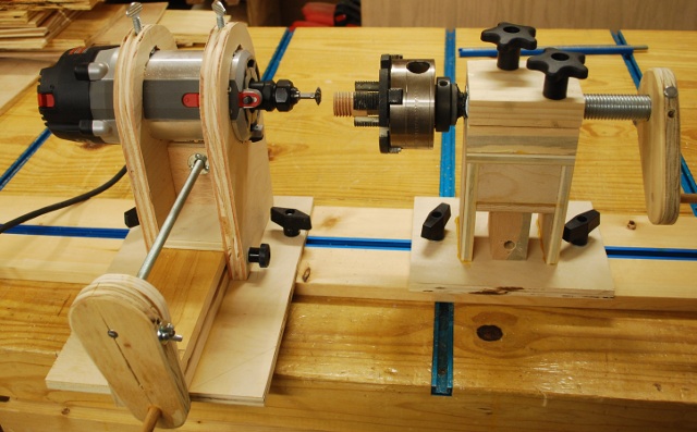
I built a jig which used a thread cutting end mill bit (60° double) in a router and a threaded rod with a lathe chuck attached to advance the piece into the cutter.
This seems like the most flexible, since the diameter of the wooden object to be threaded is not limited by a die or tap diameter, and doesn't require a lathe with very slow speed (like thread chasing), and I can cut both male and female thread.
The only restrictions are depth of threads (can't be deeper than the length of the bit sticking out of the router collet) and thread pitch (I have to make a different guide rod).
This idea didn't originate with me, I have seen numerous folks, on the web, doing this.
All my chucks have a 1" by 8 TPI (1-8) thread so I got a piece of 1-8 threaded rod along with a few 1-8 nuts, and 1" split lockwashers.
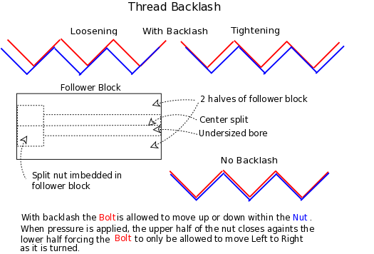
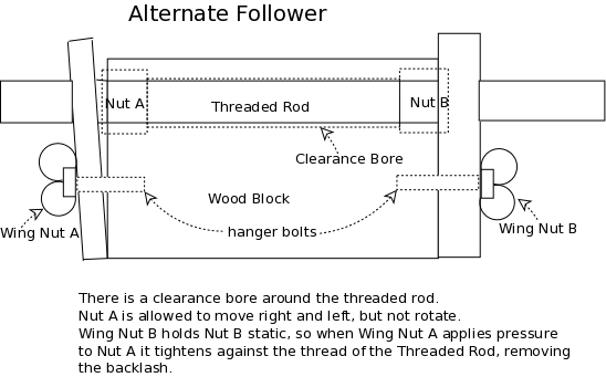
A 1-8 threaded rod and it's nut are loosely machined with lots of tolerance, resulting in too much backlash (slop or looseness in the thread) to give a smooth steady advance to the chuck when rotating against the cutter (See Backlash diagram Below).
One solution is to have a machine shop create a rod and nut with tighter tolerances, another solution is devise something that will keep the threads engaged (under slight pressure) at all times either in loosening or tightening.
In the second solution, the tension must be just tight enough so the rod doesn't wobble while advancing the piece into the cutter.
I first thought about anti-backlash gears in radar antenna drive systems but decided to try a follower that would hold the 1-8 rod more firmly (reduct backlash).
I decided to use a nut in combination with a wooden tube, if this doesn't work, I can try a threaded coupler cut in half.
I sawed a 1-8 nut in half and nested it in a wooden block, drilled with and undersized bore and split along the center as a follower.
I also squeezed a 1" split lock washer, and welded it to the rod as a stop collar to tighten the chuck against.
A flat washer would have worked as well, I just didn't have a 1" flat washer, only a split lock.
I made two attempts at this:
Using the Lathe:
In this case the follower block moved in and out and side to side to adjust for thread diameter.
The follower held the threaded rod perfectly but the tower wobbled up and down as I turned the crank to advance the chuck.
Using a Router: (Successfully)
I used the follower guide rod and tower from the first attempt, then make a mount for a router motor.
The router mount allowed the router to be adjusted side to side to adjust for diameter of male or female thread.
The guide rod and follower are mounted on a tower that only allows movement toward or away from the router, not side to side.
After I built this I saw a video on youtube where a guy used two 1-8 nuts as a follower.
One was rigidly attached the other had a little play and could be squezed, end wise, to increase pressure on the guide rod.
It appeared to work well.
Now that I have a woodthreading jig, I can start to work on all kinds of keen stuff.
If I ever want to cut other than 8 TPI, I'll make a different follower and guide rod with the 1-8 on the end for the chuck but a different pitch on the guide rod itself (this means a concentric weld of the two rods).
The first couple of tests cut good thread, even in soft material, at 8 TPI.
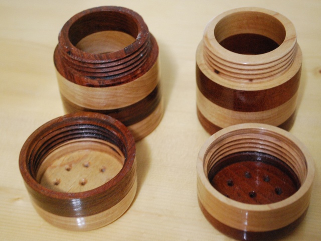
My first project is salt and pepper shakers.
Follower
|
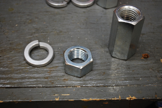
A 1" by 8 TPI nut and threaded coupler with a 1" split lock.
|
|
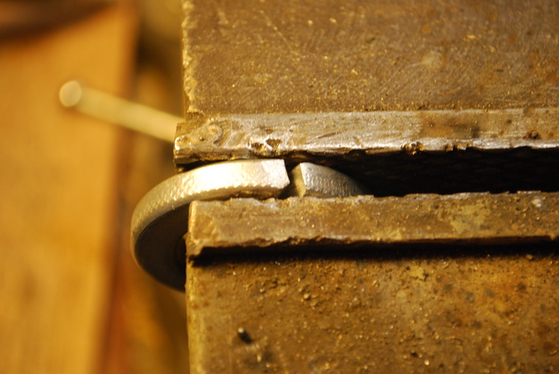
A 1" lockwasher, squeezed shut in a vise.
I'm going to use this as a stop collar on the 1" threaded rod.
|
|
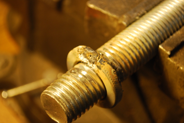
Here is the split lock, flattened, and welded to the 1" threaded rod.
You'll note, I'm not a welder, thats why it looks like a drunk dirt dobber (AKA: mud dobber) did this.
|
|
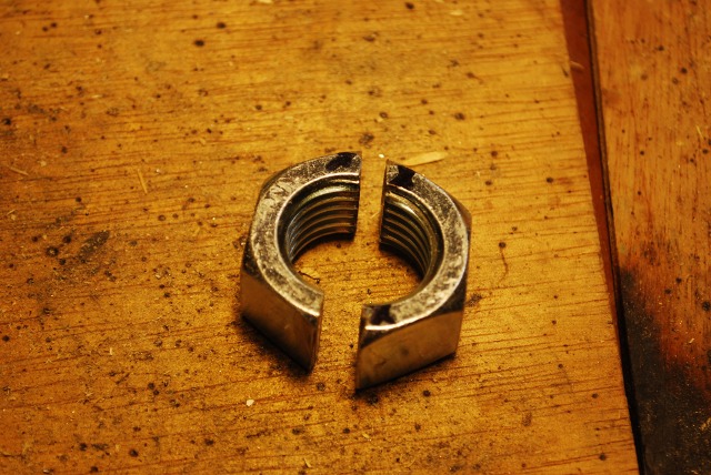
A 1" by 8 TPI nut, cut in half as part of the follower.
|
|
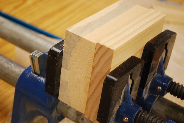
I am laminating a 2x4 to a 1x4 to make a 2-1/4" by 4" solid block for the follower.
|
|
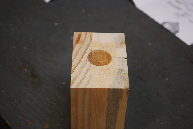
My wooden follower, laminated and center bored with a 15/16" hole.
|
|
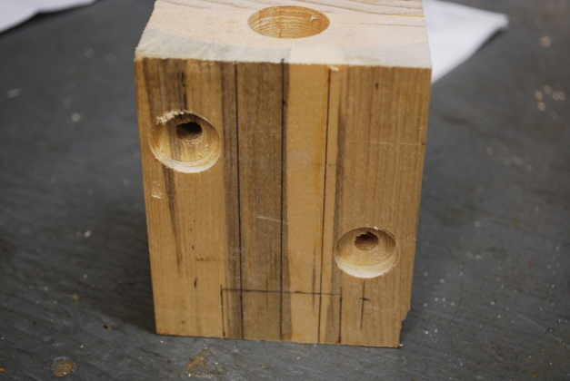
I also drilled and counterbored for 5/16" carriage bolts to adjust the tension on the follower.
|
|
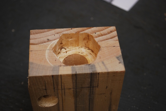
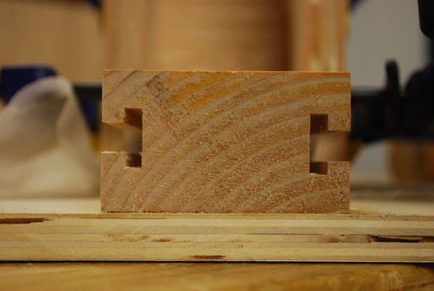
The other end of the bore, counterbored and notched for a 1" nut.
|
|
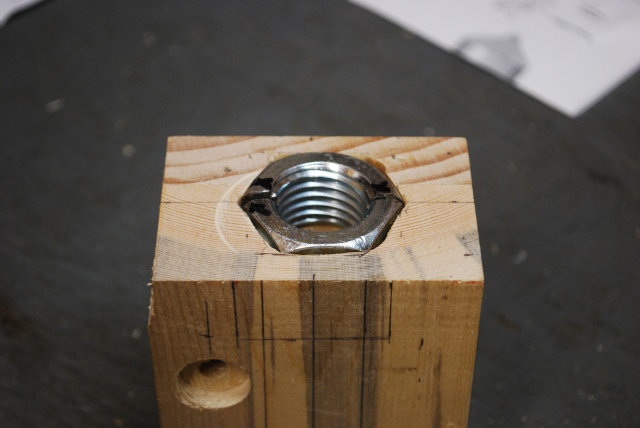
With the split nut trial fit.
You can see the center line where I'll saw the follower in half.
|

|
Heres the follower and the 1-8 chuck mounting bar.
If I ever need to cut a different pitch (other than 8 TPI) I'll have to remake these two pieces.
|
|
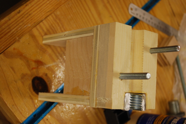
The lower half of the follower mounted on the follower tower.
This half of the nut is glued in, the upper half's nut will float free but jam up against this half.
This follower tower will be glued to a base with two tee bolts.
|
|
Upper half of the follower with the half of the 1-8 nut laying in it.
|
|
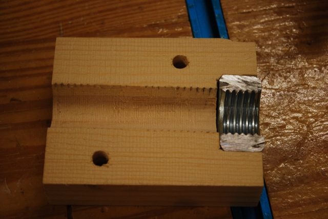
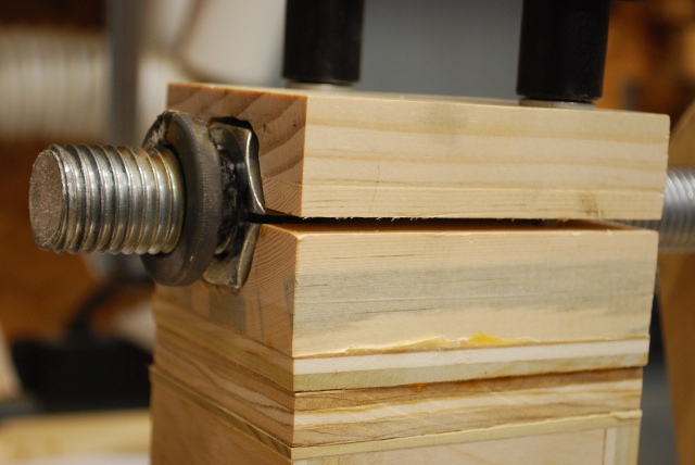
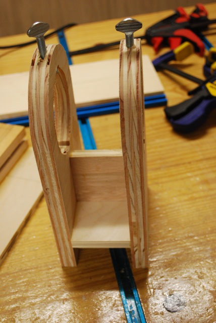
The follower assembled, note the space between the upper and lower halves of the wood and the nut, this is what allows it to tighten up on the threaded rod stopping backlash.
It doesn't require much pressure to stop the backlash, the advancing crank is still easy to turn (with a little WD-40 applied).
|
Router Holder
|
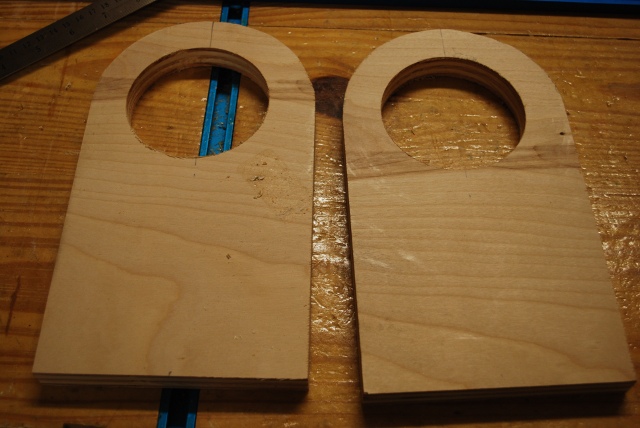
Two halves of router mount cut out of 3/4" plywood.
|
|
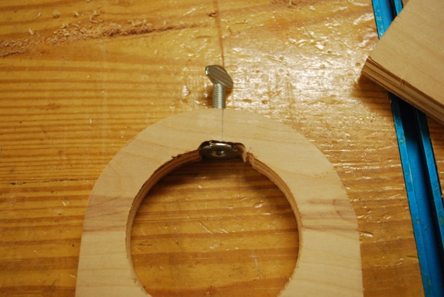
Added tee nut and thumb screw at the top to hold the router in place.
|

|
Slot for router's adjustment gear rack clearance.
I didn't modify the router motor for this project.
I also cut very small slots for the two tiny alignment pegs on the router.
|
|
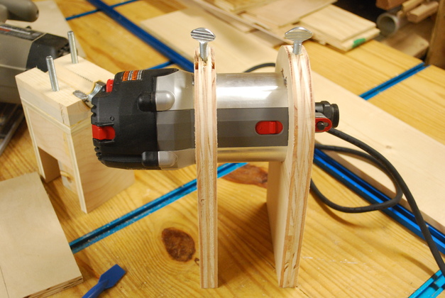
Router in it's holder
|
|
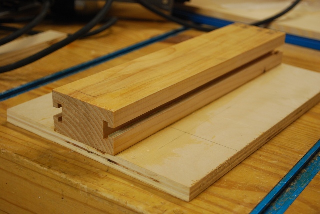
Sliding bar for router mount with tee slots cut.
This allows the router to be moved from side to side, then locked in position while cutting.
|
|
Cross supports glued into router mount.
|
|
Sliding bar glued to base.
|
|
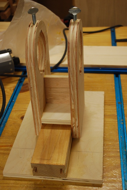
Router mount astraddle of the sliding bar.
|
|
End support being glued to front of base and sliding bar.
Tee nut should not be in this end, it will be in router mount cross support.
The other end support will be screwed on and pinned with 1/8" dowels, so I can remove the router support from the slinding bar.
|
Final Assemby
|
|
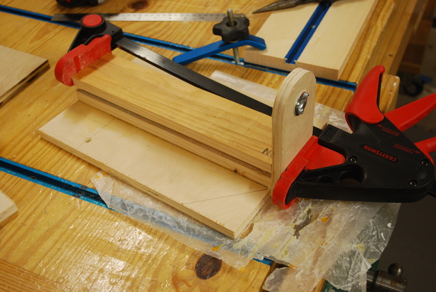
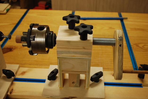
Final assembly with test dowel in chuck.
|
|
Closer look at chuck guide rod in the follower tower on sliding base.
Note the two top knobs allow you to adjust pressure on the follower, loose engough to turn but tight enought not to wobble (have backlash).
A little WD-40 made this work smoother.
|
|
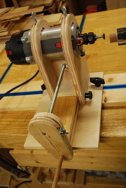
Closer look at final router mount.
You can see the tee nut under the router in the cross support.
Also note the small round tee knobs on the tee bolts in the slots on the sliding bar, and the knobs on tee bolts in the tee track.
There are jam nuts on the far end of the 3/8" threaded rod and the handle (with flat washers) holds this end.
|
Test Cut
|
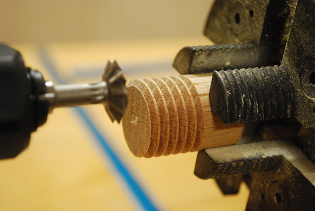
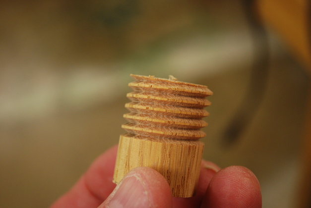
Oak dowel after test cut.
|
|
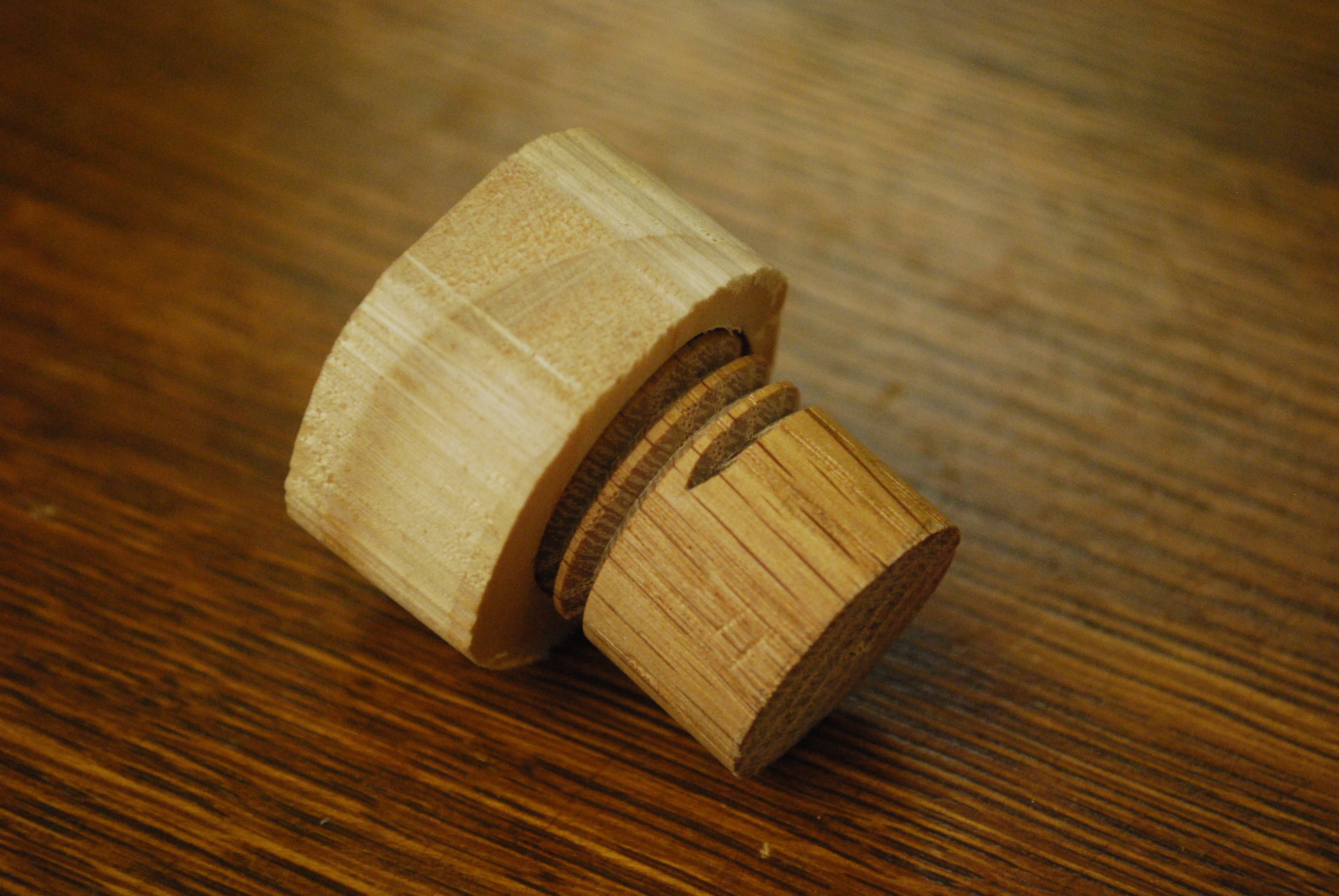
Test dowel (1" oak) after being cut on this jig.
Note the flat on top of thread peak (could have cut threads deeper) the flats are all the same width, meaning the advance of the chuck was aligned with the center line of the router.
|
|
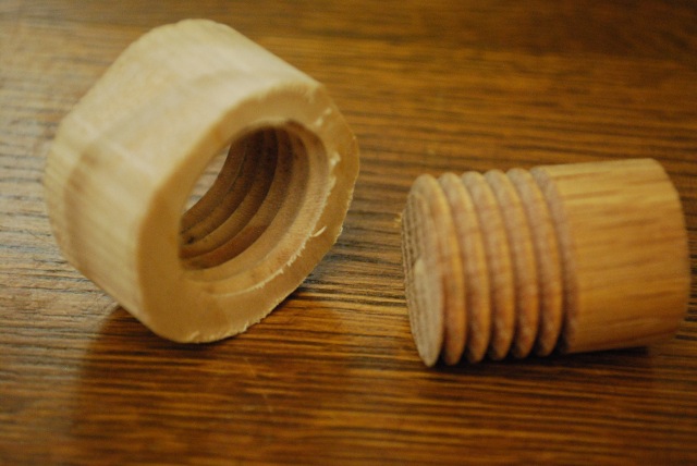
Internal thread.
I had to cluge around to get it to turn true since the test "nut" is so sloppy, but I got it.
Note: the internal thread is pretty clean even though the nut is soft white wood.
|
|
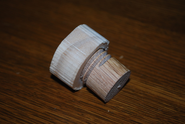
They actually thread together!
|