05/10/22: Page Origin
Replacing Adapter Pins
Most Arduino systems I build, consist of an Arduino board and several small adpater boards (Ethernet, RS_485, RTC, SD, etc.).
I like to mount the Arduino and all it's small adapter boards, as plug-ins, to a single perforated board, if possible.
This adds to the reliability, stability, and ease of maintenance of a system.
Plus, makes it easy to remove the Arduino for reprogramming.
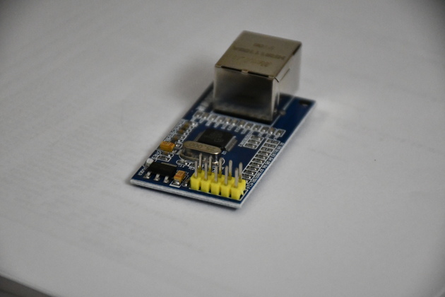
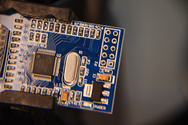
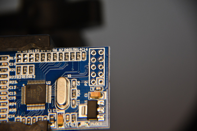
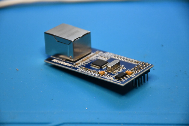
Ethernet Module
I want to mount all the gateway components on a single PCB, but the Ethernet Module's (W5500) connector pins face up instead of down, making it difficult to plug into a board.
|
|
| First I desolder the original pins.
|
| Next, I pull out the original pins and their header (you have to heat them with the soldering iron to do this).
|
| Clean pin pads with Isopropyl Alcohol.
|
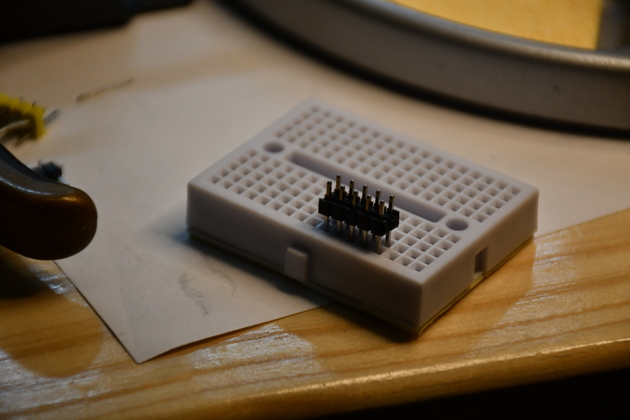
| Place new pins in breadboard (or something that will keep the straight.
|
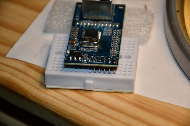
| Still plugged into breadboard, insert pins into PCB.
|
| Tack solder corner pins.
|
| Remove bread board.
|
| Solder in all pins.
|
| Clean soldered area with Isopropyl Alcohol and acid brush.
|
| Check all joints are good.
|
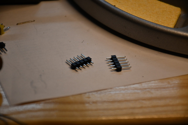
On the W5500 Ethernet module, I didn't have a dual row 5pin header so I used two 5pin strips.
This type replacement works on almost any adapter board that needs it's pin types changed.
|
Ethernet Module as it arrived from Amazon.
You can see the pins (yellow header) sticking up (wrong direction for mounting).
|
|
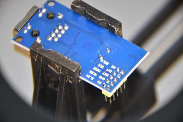
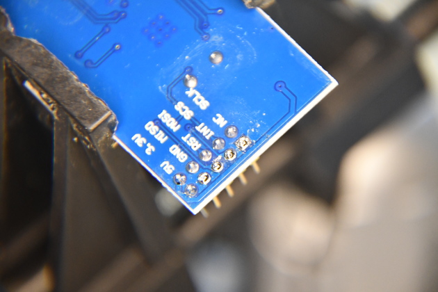
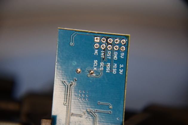
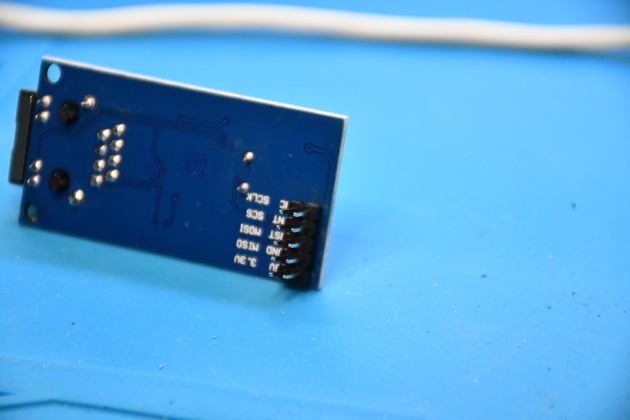
Bottom of the EthMod, you can see the pins on the top side.
|
Remove Old Pins
|
Close look at the pin's original solder joints.
I've never been able to reliably preserve the old header and pins when I remove them, so I sacrifice the old header and pins during the removal.
|
|
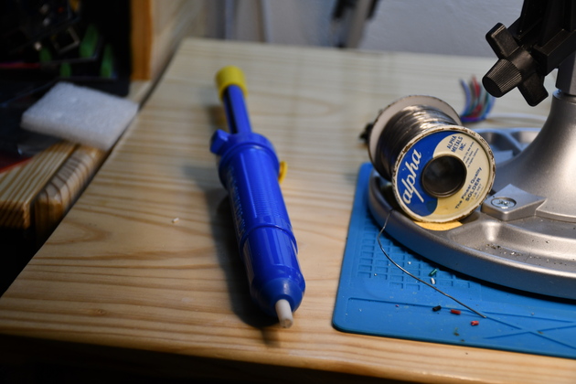
Solder sipper (slurpy).
I use a 15Watt Antec Iron and 60/40 Tin Lead .032" solder.
|
|
As I remove solder from the right hand (nearer) pins.
|
|
Bottom of EthMod board with all pins slurped (desoldered), but still in the board.
|
|
To remove a pin, I touch the iron to the soldered side while pulling on the pin, with pliers, from the other side.
As you do this, one pin at a time, each pin comes out smoothly, but when most pins are removed, the header will start to pull up, as seen in the pic.
You'll note two pins didn't want to come out of the plastic header, and the header is bending as fewer pins hold it.
|
|
A view from the top showing the header partially removed.
|
|
All pins and plastic header gone.
|
|
Each time I solder or desolder, I brush the flux off with an acid brush and Isopropyl Alcohol.
|
Install New Pins
|
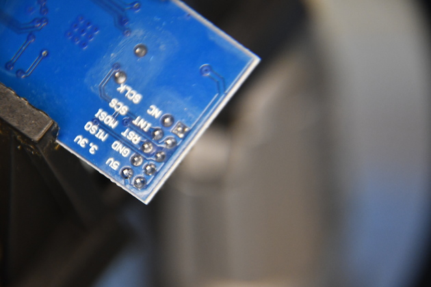
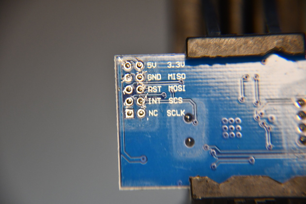
Bottom of Ethernet Module after removing up-facing pins.
|
|
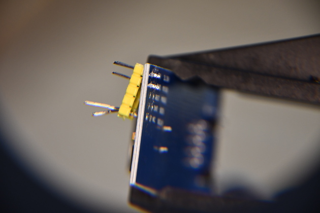
New pins (two 5-pin header strips) to be soldered into the Ethernet Module.
Note one end of pins is shorter than the other, short end goes into PCB, long end plugs into in-line socket.
|
|
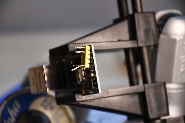
The new pins must be aligned with each other and vertical to the board, so I frequently insert pins into a small breadboard to guarantee alignment.
|
|
Now the pins are inserted into the Ethernet Module, correctly aligned, (and pointing in the correct direction) ready to solder.
I'll tack one on each end of each header strip then remove the breadboard and solder the rest.
|
Finished
|
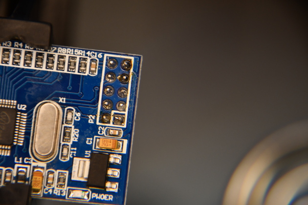
Closer look at top of board after soldering in new header and brushing with Isopropyl Alcohol to remove flux.
|
|
Same at different angle.
When I look at solder joints, I always try several light angles, helps to be sure the solder joints are OK.
|
|
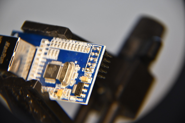
Top of the Ethernet Module with pins reversed.
|
|
Bottom, showing pins, ready to plug into a board.
|
