: Page Origin
Building The Env Server's Pcb
|
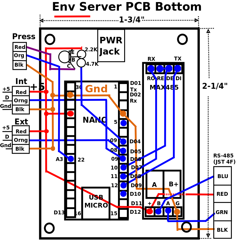
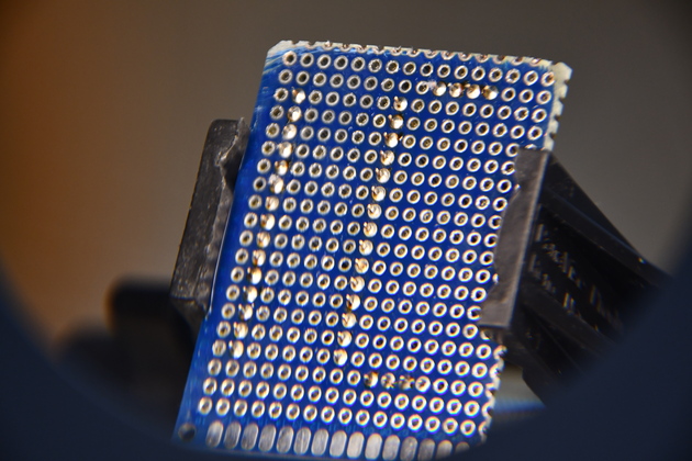
Bottom of the Env server board.
You can see the Nano's and MAX485's header pins, already soldered.
|
|
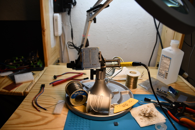
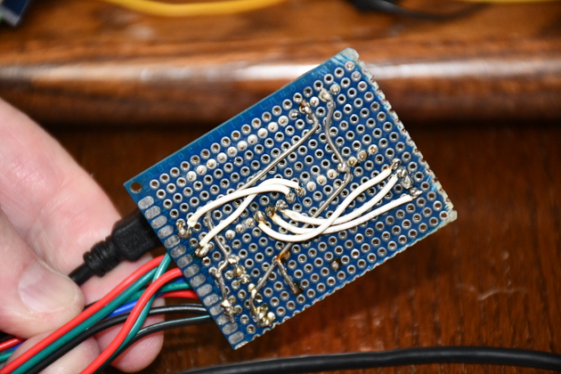
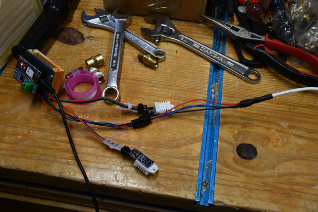
Finished Env Server being tested.
First I ran the ground buss wire (tinned copper), then the +5 buss (tinned copper), and finally the signal wires (white).
|

|
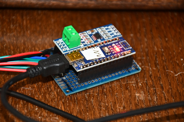
Final Env server PCB.
|
|
Finished Env Server top, being tested.
|
Terminating RS-485 Cable
I'm using a 4 wire, shielded twisted pair cable, since I run powera (Red) and ground (Black) through it to Nano Servers.
I tie the drain wire (bare copper) to the gound (Black), so far no probs, but I'm only running 57600 Baud.
I strip about 4mm of insulation from the ends, tin any stranded ends, then bend a hook in each wire.
I put HS (heat shrink) on the connector wires, hook red to red, black to black, etc., squeez the hooks together, then solder.
Last I heat the HS to secure and insulate the joint.

|
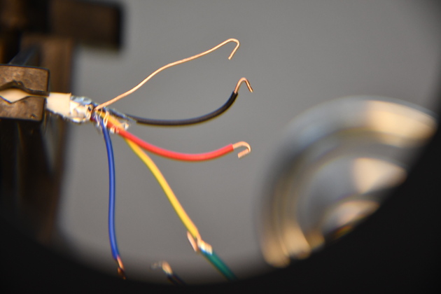
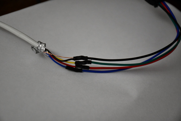
The shielded twisted pair cable, 4 wire with shield.
The Red & Black wires will be +5 and ground, the blue and yellow will be RS-485 B and A, respectively.
|
|
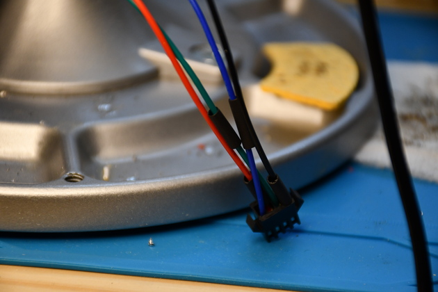
The 4 wire shielded twisted pair cable on the left.
Note the Red, Black, and Blue connector wires have a mating color in the 4 wire cable so I had to match the green connector wire to the yellow cable wire.
Also note the bare wire is called a drain wire and connects to the foil shield in the cable.
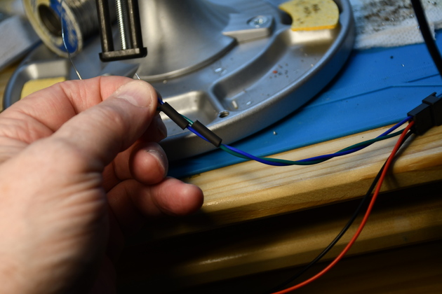
Before actually connecting the wires, I put a short piece of HS on the connector wires.
e
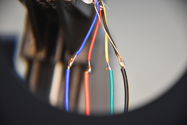
The connector wires are stranded so I tinned them, then put a little hook on the end of all wires to be joined.
|
|
Sliding HS onto the connector leads.
|
|
You can see the HS on the connector end (away from heat of soldering).
|
|
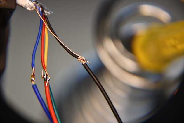
Then I hook both ends of wire to be joined and solder them.
Note I soldered the drain wire to the black ground wire.
|
|
After the soldering is done, I slide the HS (heat shrink) up over the sodered joint and heat it.
|
|
Closer look at individual HS cable termination.
|
|
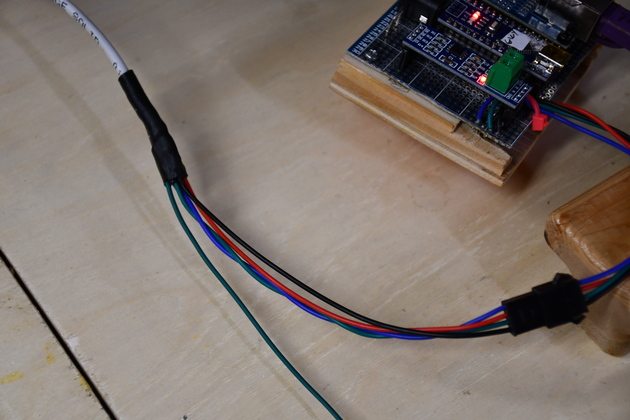
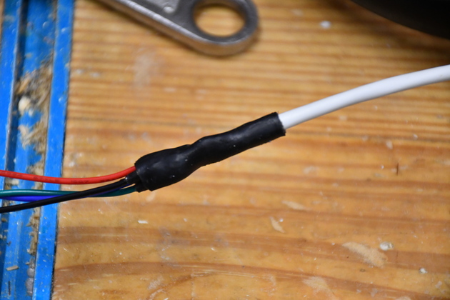
Final, I put a larger HS (heat shrink) over the 4 individual wire HSs.
Note this is the Gateway end, it has an extra ground wire to ground the entire system.
|
|
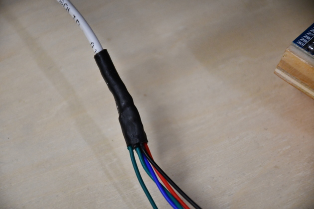
Close up of the larger HS.
|
|
The Env Server (slave) end of the the RS-485 cable.
|
|
Closer look, note large HS over smaller HS.
|