Region points
 ../_images/define-zone-region-sample.jpg
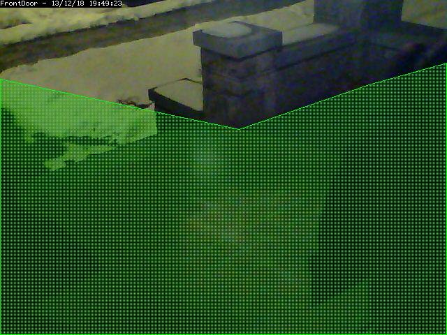
The sample region shown to the right shows a region defined by 6 control
points. The shape of the region causes the check methods to ignore the
sidewalk and areas of the porch wall that receive changing sunlight; two
conditions that are not of interest in this zone.
../_images/define-zone-region-sample.jpg
The sample region shown to the right shows a region defined by 6 control
points. The shape of the region causes the check methods to ignore the
sidewalk and areas of the porch wall that receive changing sunlight; two
conditions that are not of interest in this zone.
A region is a part of the captured image that is of interest for this
zone. By default, a region is configured to cover the whole captured
image. Depending on the selected type of this zone, the shape of the
region can be adjusted to accommodate multiple effects. This can be done
by dragging the control points in the reference image around, or by
altering the coordinates found in the controls below the reference image.
Clicking on a control point in the reference image highlights the
coordinates in the table below. Clicking the + button in a point row adds
a control point between this point and the next; clicking the - button
removes this control point. It is possible to accidentally place a control
point outside of the valid coordinates of the image. This will prevent the
monitor from working properly. You can make zones almost any shape you
like; except that zones may not self-intersect (i.e. edges crossing over
each other).
Alarm Colour These parameters can be used to individually colorize the zone overlay pattern. Alarms in this zone will be highlighted in the alarm colour. This option is irrelevant for Preclusive and Inactive zones and will be disabled.
Alarm Check Methods There are 3 Alarm Check Methods. They are sequential, and are layered: In AlarmedPixels mode, only the AlarmedPixel analysis is performed. In FilteredPixels mode, the AlarmedPixel analysis is performed first, followed by the FilteredPixel analysis. In the Blobs mode, all 3 analysis methods are performed in order. An alarm is only triggered if all of the enabled analysis modes are triggered. For performance reasons, as soon as the criteria for one of the analysis modes is not met, the alarm checking for the frame is complete. Since the subsequent modes each require progressively more computations, it is a good idea to tune the parameters in each of the activated layers. For reference purposes, the Zone Area box shows the area of the entire region of interest. In percent mode, this is 100. In Pixels mode, this is the pixel count of the region. All 3 Min/Max Area parameter groups are based on the Zone Area as the maximum sensible value, and all 3 are interpreted in the units specified in the Units input.
AlarmedPixels Alarmed pixels is the first layer of analysis, and is always enabled. Its recommended that you start with this method and move on to the subsequent methods once the effects of the basic parameters are understood. In the AlarmedPixels mode, 2 parameter categories are available for tuning: Min/Max Pixel Threshold, and Min/Max Alarmed Area.
Min/Max Pixel Threshold (0-255) In the AlarmedPixel layer of analysis, each individual pixel of the image is compared to the current reference image. Pixels that are different from the reference image are considered alarmed pixels. However, small aberrations in lighting or auto exposure camera adjustments may cause the explicit value of a pixel to vary by small amounts from image to image. This parameter allows you to set the limits of what will be considered a changed pixel. For example, if your camera points to a blank white wall, and you raise a black colored item into view, then the change in any one pixel will be great, indeed, extreme. If however, you raise a white piece of paper, then the change in an individual pixel will be less. The minimum pixel threshold setting should be high enough to cause minor lighting, imaging, or compression changes to be ignored. Setting the minimum value too high, may allow a white cat to walk undetected across the view of the white wall. A good starting point for the minimum pixel threshold is 40, meaning that the difference in pixel value from must be greater than 40. A good default for the maximum pixel threshold is 0 (indicating that all differences above the minimum threshold are considered a change.)
Min/Max Alarmed Area The count of alarmed pixels (or percentage of alarmed pixels relative to the pixel area of the region if in percent mode) is used in this first layer of analysis to determine if an alarm is triggered. If the count or percentage is above the minimum alarmed area, but less than the maximum alarmed area, an alarm is triggered. These settings depend on the size of the object you are trying to capture: a value too low may cause false alarms, while a value too high might not detect small objects. A good starting point for both the minimum and maximum are 0 and 0, indicating that any number of alarmed pixels (or any percentage) greater than 0 will trigger an alarm. The frame scores from logged events can then be used to bring the minimum up to a reasonable value. An alternative starting point for the minimum alarmed area (in percent) is 25% of the area that an object of interest takes up in the region. For example, if you approximate that a subject moving through the frame takes up 30% of the frame, then a good starting minimum area is about 7.5%.
FilteredPixels Selecting the FilteredPixels Alarm Check Method adds an additional layer of analysis to the AlarmedPixels check along with 2 additional parameter categories for tuning. This layer works by analyzing the alarmed pixels identified in the first layer. Alarmed pixels are disregarded, in this and future layers if enabled, if they are not in groups of a minimum small square size. Primarily, this filtering removes isolated alarmed pixels that may be artifacts of the camera, lens, or compression.
Filter Width/Height (pixels) This parameter is always specified in Pixels, even when Percentages are the selected units. It specifies the size of the group of pixels surrounding a given pixel that must be in alarmed pixels for the pixel itself to be considered an alarmed pixel. The width and height should always be an odd number. 3 x 3 is the default value, and 5 x 5 is also suggested as a sensible alternative. Avoid using large numbers for the width and height of the filter area. When using the Blobs Alarm Check Method, FilteredPixels can be effectively disabled by setting either the width or height to a value less than 1.
Min/Max Filtered Area Applying the filtering analysis results in an area that is less than or equal to the alarmed area. Thus the minimum and maximum filtered area parameters for alarm should be equal to or less than the corresponding alarm area parameters, or the FilteredPixels analysis will never trigger an alarm. In particular, it is useful to raise the minimum alarmed area parameter until false events from image artifacts disappear, and setting a minimum filtered area parameter less the minimum alarmed area parameter by enough to capture small events of interest.
Blobs
 ../_images/define-zone-blob.jpg
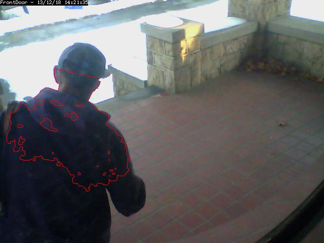
This image shows an image with 1 identified blob. The blob is outlined in
the Alarm Colour specified above.
When two or more Filtered areas touch or share a boundary, it is sensible
to evaluate the regions as one contiguous area instead of separate
entities. A Blob is a contiguous area made up of multiple filtered areas.
Whereas FilteredPixes is useful for excluding parts of the image that are
not part of the actual scene, Blob filtering is better suited to
disregarding areas of the actual scene that are not of interest.
../_images/define-zone-blob.jpg
This image shows an image with 1 identified blob. The blob is outlined in
the Alarm Colour specified above.
When two or more Filtered areas touch or share a boundary, it is sensible
to evaluate the regions as one contiguous area instead of separate
entities. A Blob is a contiguous area made up of multiple filtered areas.
Whereas FilteredPixes is useful for excluding parts of the image that are
not part of the actual scene, Blob filtering is better suited to
disregarding areas of the actual scene that are not of interest.
Selecting the Blobs Alarm Check Method opens up all of the available
parameters. Enabling Blobs adds one more layer of analysis to the
AlarmedPixel and FilteredPixel checks in the determination of a valid
alarm along along with 2 additional parameter categories for tuning: the
size of the blobs, and the number of blobs. A Blob is not necessarily the
whole object that may be of interest. In the example image, the subject is
moving, but only a portion of him is marked as a blob. This is because as
the subject moves, many pixels of the image do not change in value beyond
the set threshold. A pixel that is representing the subject’s shoulder
in one frame may be representing his back in the next, however, the value
of the pixel remains nearly the same.
Min/Max Blob Area The blob area parameters control the smallest and largest contiguous areas that are to be considered a blob. A good value for the maximum area is the default of 0. (There is no upper bound for the size of a contiguous area that will still be considered a blob.)
Min/Max Blobs Normally, you would want any positive number of blobs to trigger an event, so the default value of 1 should suffice. In some circumstances, it may benefit to have only one blob NOT trigger an event, in which case, setting this value to 2 or higher may serve some special purpose. A good value for the maximum blobs is the default of 0. (There is no upper bound for the number of blobs that will trigger an event. Use the maximum blobs parameter can be used to tune out events that show a high number of blobs.
Overload Frame Ignore Count This setting specifies the number of frames to NOT raise an alarm after an overload. In this context, overload is defined as a detected change too big to raise an alarm. Depending on the alarm check method that could be * Number of alarmed pixels > Max Alarmed Area or * Number of filtered pixels > Max Filtered Area or * Number of Blobs > Max Blobs The idea is that after a change like a light going on that is considered too big to count as an alarm, it could take a couple of frames for things to settle down again.
Other information Refer to this user contributed Zone guide for additional information will illustrations if you are new to zones and need more help.