Defining Zones

The next important thing to do with a new monitor is set up Zones for it to
use. By default you’ll already have one generated for you when you created
your monitor (the default zone is the full area captured by the monitor) but
you might want to modify it or add others.

Click on the Zones column for your monitor and you should see a small popup
window appear which contains an image from your camera overlain with a stippled
pattern representing your zone. In the default case this will cover the
whole image. The colour of the zones appearing here is determined by what type
they are:
- default zone is Active and so will be red,
- Inclusive zones are orange,
- exclusive zones are purple,
- preclusive zones are blue,
- inactive zones are white.
Basic parameters Name Each Zone can be named for reference purposes. It is used for logging and debugging. Choose a name that helps you identify your zones. Type This is one of the more important concepts in ZoneMinder and there are six to choose from.
- Active Triggers an alarm when motion is detected within it. This is the zone type you’ll use most often, and which will be set for your default zone. Only Active and Exclusive zones can trigger an alarm.
- Inclusive This zone type can be used for any zones that you want to trigger an alarm only if at least one other Active zone has already triggered one. This might be for example to cover an area of the image like a plant or tree which moves a lot and which would trigger lots of alarms. Perhaps this is behind an area you’d like to monitor though, in this case you’d create an active zone covering the non-moving parts and an inclusive zone covering the tree perhaps with less sensitive detection settings also. If something triggered an alarm in the Active zone and also in the Inclusive zone they would both be registered and the resulting alarm would be that much bigger than if you had blanked it out altogether.
- Exclusive Triggers an alarm when motion is detected within it, as long as no alarms have already been triggered in an Active zone. This is the most specialized of the zone types. For instance in the camera covering my garden I keep watch for a hedgehog that visits most nights and scoffs the food out of my cats bowls. By creating a sensitive Exclusive zone in that area I can ensure that a hedgehog alarm will only trigger if there is activity in that small area. If something much bigger occurs, like someone walking by it will trigger a regular alarm and not one from the Exclusive zone. Thus I can ensure I get alarms for big events and also special small events but not the noise in between.
- Preclusive This zone type is relatively recent. It is called a Preclusive zone because if it is triggered it actually precludes an alarm being generated for that image frame. So motion or other changes that occur in a Preclusive zone will have the effect of ensuring that no alarm occurs at all. The application for this zone type is primarily as a shortcut for detecting general large-scale lighting or other changes. Generally this may be achieved by limiting the maximum number of alarm pixels or other measure in an Active zone. However in some cases that zone may cover an area where the area of variable illumination occurs in different places as the sun and/or shadows move and it thus may be difficult to come up with general values. Additionally, if the sun comes out rapidly then although the initial change may be ignored in this way as the reference image catches up an alarm may ultimately be triggered as the image becomes less different. Using one or more Preclusive zones offers a different approach. Preclusive zones are designed to be fairly small, even just a few pixels across, with quite low alarm thresholds. They should be situated in areas of the image that are less likely to have motion occur such as high on a wall or in a corner. Should a general illumination change occur they would be triggered at least as early as any Active zones and prevent any other zones from generating an alarm. Obviously careful placement is required to ensure that they do not cancel any genuine alarms or that they are not so close together that any motion just hops from one Preclusive zone to another. Preclusive zones may also be used to reduce processing time by situating one over an Active zone. The Preclusive zone is processed first; if it is small, and is triggered, the rest of the zone/image will not be processed. See Extend Alarm Frame Count below for a way to hold the preclusive zone active for an extended period.
- Inactive Suppresses the detection of motion within it. This can be layered on top of any other zone type, preventing motion within the Inactive zone from being effective for any other zone type. Use inactive zones to cover areas in which nothing notable will ever happen or where you get false alarms that don’t relate to what you are trying to monitor. Inactive zones may be overlaid on other zones to blank out areas, and are processed first (with the exception of Privacy zones, see below). As a general practice, you should try and make zones abut each other instead of overlapping to avoid repeated duplicate processing of the same area.
- Privacy Blackens the pixels within it. This can be used if you want to hide some regions in the image if the situation does not allow another solution. This zone type is different to all the others in that it gets processed as soon as possible during capture (even before the timestamp gets into the image) and not in the analyzing process. So if you add, change or delete a Privacy zone, you don’t see the changes in the image until the capture process gets restarted. This will be done automatically, but needs a few seconds.
Preset The preset chooser sets sensible default values based on computational needs (fast v. best) and sensitivity (low, medium, high.) It is not required that you select a preset, and you can alter any of the parameters after choosing a preset. For a small number of monitors with ZoneMinder running on modern equipment, Best, high sensitivity can be chosen as a good starting point. It is important to understand that the available presets are intended merely as a starting point. Since every camera’s view is unique, they are not guaranteed to work properly in every case. Presets tend to work acceptably for indoor cameras, where the objects of interest are relatively close and there typically are few or no unwanted objects moving within the cameras view. Presets, on the other hand, tend to not work acceptably for outdoor cameras, where the field of view is typically much wider, objects of interest are farther away, and changing weather patterns can cause false triggers. For outdoor cameras in particular, you will almost certainly have to tune your motion detection zone to get desired results. Please refer to this guide to learn how to do this. Units
- Pixels - Selecting this option will allow many of the following values to be entered (or viewed) in units of pixels.
- Percentage - Selecting this option will allow may of the following values to be entered (or viewed) as a percentage. The sense of the percentage values refers to the area of the zone and not the image as a whole. This makes trying to work out necessary sizes rather easier.
Region points
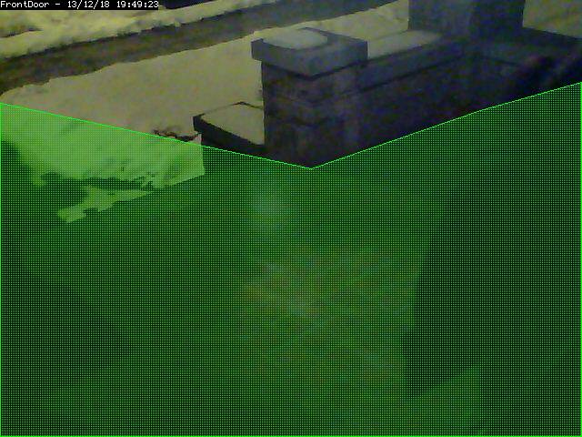 The sample region shown to the right shows a region defined by 6 control
points. The shape of the region causes the check methods to ignore the
sidewalk and areas of the porch wall that receive changing sunlight; two
conditions that are not of interest in this zone.
A region is a part of the captured image that is of interest for this
zone. By default, a region is configured to cover the whole captured image.
Depending on the selected type of this zone, the shape of the region can be
adjusted to accommodate multiple effects. This can be done by dragging the
control points in the reference image around, or by altering the coordinates
found in the controls below the reference image. Clicking on a control point
in the reference image highlights the coordinates in the table below.
Clicking the + button in a point row adds a control point between this point
and the next; clicking the - button removes this control point. It is
possible to accidentally place a control point outside of the valid
coordinates of the image. This will prevent the monitor from working
properly. You can make zones almost any shape you like; except that zones
may not self-intersect (i.e. edges crossing over each other).
Alarm Colour
These parameters can be used to individually colorize the zone overlay
pattern. Alarms in this zone will be highlighted in the alarm colour. This
option is irrelevant for Preclusive and Inactive zones and will be
disabled.
Alarm Check Methods
There are 3 Alarm Check Methods. They are sequential, and are layered:
In AlarmedPixels mode, only the AlarmedPixel analysis is performed. In
FilteredPixels mode, the AlarmedPixel analysis is performed first, followed
by the FilteredPixel analysis. In the Blobs mode, all 3 analysis methods are
performed in order. An alarm is only triggered if all of the enabled
analysis modes are triggered. For performance reasons, as soon as the
criteria for one of the analysis modes is not met, the alarm checking for
the frame is complete. Since the subsequent modes each require progressively
more computations, it is a good idea to tune the parameters in each of the
activated layers.
For reference purposes, the Zone Area box shows the area of the entire
region of interest. In percent mode, this is 100. In Pixels mode, this is
the pixel count of the region. All 3 Min/Max Area parameter groups are based
on the Zone Area as the maximum sensible value, and all 3 are interpreted in
the units specified in the Units input.
AlarmedPixel
Alarmed pixels is the first layer of analysis, and is always enabled.
Its recommended that you start with this method and move on to the
subsequent methods once the effects of the basic parameters are understood.
In the AlarmedPixels mode, 2 parameter categories are available for tuning:
Min/Max Pixel Threshold, and Min/Max Alarmed Area.
Min/Max Pixel Threshold (0-255)
In the AlarmedPixel layer of analysis, each individual pixel of the
image is compared to the current reference image. Pixels that are different
from the reference image are considered alarmed pixels. However, small
aberrations in lighting or auto exposure camera adjustments may cause the
explicit value of a pixel to vary by small amounts from image to image. This
parameter allows you to set the limits of what will be considered a changed
pixel. For example, if your camera points to a blank white wall, and you
raise a black colored item into view, then the change in any one pixel will
be great, indeed, extreme. If however, you raise a white piece of paper,
then the change in an individual pixel will be less.
The minimum pixel threshold setting should be high enough to cause minor
lighting, imaging, or compression changes to be ignored. Setting the minimum
value too high, may allow a white cat to walk undetected across the view of
the white wall. A good starting point for the minimum pixel threshold is 40,
meaning that the difference in pixel value from must be greater than 40. A
good default for the maximum pixel threshold is 0 (indicating that all
differences above the minimum threshold are considered a change.)
Min/Max Alarmed Area
The count of alarmed pixels (or percentage of alarmed pixels relative to
the pixel area of the region if in percent mode) is used in this first layer
of analysis to determine if an alarm is triggered. If the count or
percentage is above the minimum alarmed area, but less than the maximum
alarmed area, an alarm is triggered. These settings depend on the size of
the object you are trying to capture: a value too low may cause false
alarms, while a value too high might not detect small objects. A good
starting point for both the minimum and maximum are 0 and 0, indicating that
any number of alarmed pixels (or any percentage) greater than 0 will trigger
an alarm. The frame scores from logged events can then be used to bring the
minimum up to a reasonable value. An alternative starting point for the
minimum alarmed area (in percent) is 25% of the area that an object of
interest takes up in the region. For example, if you approximate that a
subject moving through the frame takes up 30% of the frame, then a good
starting minimum area is about 7.5%.
FilteredPixels
Selecting the FilteredPixels Alarm Check Method adds an additional layer
of analysis to the AlarmedPixels check along with 2 additional parameter
categories for tuning. This layer works by analyzing the alarmed pixels
identified in the first layer. Alarmed pixels are disregarded, in this and
future layers if enabled, if they are not in groups of a minimum small
square size. Primarily, this filtering removes isolated alarmed pixels that
may be artifacts of the camera, lens, or compression.
Filter Width/Height (pixels)
This parameter is always specified in Pixels, even when Percentages are
the selected units. It specifies the size of the group of pixels surrounding
a given pixel that must be in alarmed pixels for the pixel itself to be
considered an alarmed pixel. The width and height should always be an odd
number. 3 x 3 is the default value, and 5 x 5 is also suggested as a
sensible alternative. Avoid using large numbers for the width and height of
the filter area. When using the Blobs Alarm Check Method, FilteredPixels can
be effectively disabled by setting either the width or height to a value
less than 1.
Min/Max Filtered Area
Applying the filtering analysis results in an area that is less than or
equal to the alarmed area. Thus the minimum and maximum filtered area
parameters for alarm should be equal to or less than the corresponding alarm
area parameters, or the FilteredPixels analysis will never trigger an alarm.
In particular, it is useful to raise the minimum alarmed area parameter
until false events from image artifacts disappear, and setting a minimum
filtered area parameter less the minimum alarmed area parameter by enough to
capture small events of interest.
The sample region shown to the right shows a region defined by 6 control
points. The shape of the region causes the check methods to ignore the
sidewalk and areas of the porch wall that receive changing sunlight; two
conditions that are not of interest in this zone.
A region is a part of the captured image that is of interest for this
zone. By default, a region is configured to cover the whole captured image.
Depending on the selected type of this zone, the shape of the region can be
adjusted to accommodate multiple effects. This can be done by dragging the
control points in the reference image around, or by altering the coordinates
found in the controls below the reference image. Clicking on a control point
in the reference image highlights the coordinates in the table below.
Clicking the + button in a point row adds a control point between this point
and the next; clicking the - button removes this control point. It is
possible to accidentally place a control point outside of the valid
coordinates of the image. This will prevent the monitor from working
properly. You can make zones almost any shape you like; except that zones
may not self-intersect (i.e. edges crossing over each other).
Alarm Colour
These parameters can be used to individually colorize the zone overlay
pattern. Alarms in this zone will be highlighted in the alarm colour. This
option is irrelevant for Preclusive and Inactive zones and will be
disabled.
Alarm Check Methods
There are 3 Alarm Check Methods. They are sequential, and are layered:
In AlarmedPixels mode, only the AlarmedPixel analysis is performed. In
FilteredPixels mode, the AlarmedPixel analysis is performed first, followed
by the FilteredPixel analysis. In the Blobs mode, all 3 analysis methods are
performed in order. An alarm is only triggered if all of the enabled
analysis modes are triggered. For performance reasons, as soon as the
criteria for one of the analysis modes is not met, the alarm checking for
the frame is complete. Since the subsequent modes each require progressively
more computations, it is a good idea to tune the parameters in each of the
activated layers.
For reference purposes, the Zone Area box shows the area of the entire
region of interest. In percent mode, this is 100. In Pixels mode, this is
the pixel count of the region. All 3 Min/Max Area parameter groups are based
on the Zone Area as the maximum sensible value, and all 3 are interpreted in
the units specified in the Units input.
AlarmedPixel
Alarmed pixels is the first layer of analysis, and is always enabled.
Its recommended that you start with this method and move on to the
subsequent methods once the effects of the basic parameters are understood.
In the AlarmedPixels mode, 2 parameter categories are available for tuning:
Min/Max Pixel Threshold, and Min/Max Alarmed Area.
Min/Max Pixel Threshold (0-255)
In the AlarmedPixel layer of analysis, each individual pixel of the
image is compared to the current reference image. Pixels that are different
from the reference image are considered alarmed pixels. However, small
aberrations in lighting or auto exposure camera adjustments may cause the
explicit value of a pixel to vary by small amounts from image to image. This
parameter allows you to set the limits of what will be considered a changed
pixel. For example, if your camera points to a blank white wall, and you
raise a black colored item into view, then the change in any one pixel will
be great, indeed, extreme. If however, you raise a white piece of paper,
then the change in an individual pixel will be less.
The minimum pixel threshold setting should be high enough to cause minor
lighting, imaging, or compression changes to be ignored. Setting the minimum
value too high, may allow a white cat to walk undetected across the view of
the white wall. A good starting point for the minimum pixel threshold is 40,
meaning that the difference in pixel value from must be greater than 40. A
good default for the maximum pixel threshold is 0 (indicating that all
differences above the minimum threshold are considered a change.)
Min/Max Alarmed Area
The count of alarmed pixels (or percentage of alarmed pixels relative to
the pixel area of the region if in percent mode) is used in this first layer
of analysis to determine if an alarm is triggered. If the count or
percentage is above the minimum alarmed area, but less than the maximum
alarmed area, an alarm is triggered. These settings depend on the size of
the object you are trying to capture: a value too low may cause false
alarms, while a value too high might not detect small objects. A good
starting point for both the minimum and maximum are 0 and 0, indicating that
any number of alarmed pixels (or any percentage) greater than 0 will trigger
an alarm. The frame scores from logged events can then be used to bring the
minimum up to a reasonable value. An alternative starting point for the
minimum alarmed area (in percent) is 25% of the area that an object of
interest takes up in the region. For example, if you approximate that a
subject moving through the frame takes up 30% of the frame, then a good
starting minimum area is about 7.5%.
FilteredPixels
Selecting the FilteredPixels Alarm Check Method adds an additional layer
of analysis to the AlarmedPixels check along with 2 additional parameter
categories for tuning. This layer works by analyzing the alarmed pixels
identified in the first layer. Alarmed pixels are disregarded, in this and
future layers if enabled, if they are not in groups of a minimum small
square size. Primarily, this filtering removes isolated alarmed pixels that
may be artifacts of the camera, lens, or compression.
Filter Width/Height (pixels)
This parameter is always specified in Pixels, even when Percentages are
the selected units. It specifies the size of the group of pixels surrounding
a given pixel that must be in alarmed pixels for the pixel itself to be
considered an alarmed pixel. The width and height should always be an odd
number. 3 x 3 is the default value, and 5 x 5 is also suggested as a
sensible alternative. Avoid using large numbers for the width and height of
the filter area. When using the Blobs Alarm Check Method, FilteredPixels can
be effectively disabled by setting either the width or height to a value
less than 1.
Min/Max Filtered Area
Applying the filtering analysis results in an area that is less than or
equal to the alarmed area. Thus the minimum and maximum filtered area
parameters for alarm should be equal to or less than the corresponding alarm
area parameters, or the FilteredPixels analysis will never trigger an alarm.
In particular, it is useful to raise the minimum alarmed area parameter
until false events from image artifacts disappear, and setting a minimum
filtered area parameter less the minimum alarmed area parameter by enough to
capture small events of interest.
Blobs
 This image shows an image with 1 identified blob. The blob is outlined in
the Alarm Colour specified above.
When two or more Filtered areas touch or share a boundary, it is sensible to
evaluate the regions as one contiguous area instead of separate entities. A
Blob is a contiguous area made up of multiple filtered areas. Whereas
FilteredPixes is useful for excluding parts of the image that are not part
of the actual scene, Blob filtering is better suited to disregarding areas
of the actual scene that are not of interest.
Selecting the Blobs Alarm Check Method opens up all of the available
parameters. Enabling Blobs adds one more layer of analysis to the
AlarmedPixel and FilteredPixel checks in the determination of a valid alarm
along along with 2 additional parameter categories for tuning: the size of
the blobs, and the number of blobs. A Blob is not necessarily the whole
object that may be of interest. In the example image, the subject is moving,
but only a portion of him is marked as a blob. This is because as the
subject moves, many pixels of the image do not change in value beyond the
set threshold. A pixel that is representing the subject’s shoulder in one
frame may be representing his back in the next, however, the value of the
pixel remains nearly the same.
Min/Max Blob Area
The blob area parameters control the smallest and largest contiguous
areas that are to be considered a blob. A good value for the maximum area is
the default of 0. (There is no upper bound for the size of a contiguous area
that will still be considered a blob.)
Min/Max Blobs
Normally, you would want any positive number of blobs to trigger an
event, so the default value of 1 should suffice. In some circumstances, it
may benefit to have only one blob NOT trigger an event, in which case,
setting this value to 2 or higher may serve some special purpose. A good
value for the maximum blobs is the default of 0. (There is no upper bound
for the number of blobs that will trigger an event. Use the maximum blobs
parameter can be used to tune out events that show a high number of blobs.
Overload Frame Ignore Count
This setting specifies the number of frames to NOT raise an alarm after
an overload. In this context, overload is defined as a detected change too
big to raise an alarm. Depending on the alarm check method that could be *
Number of alarmed pixels > Max Alarmed Area or * Number of filtered pixels >
Max Filtered Area or * Number of Blobs > Max Blobs The idea is that after a
change like a light going on that is considered too big to count as an
alarm, it could take a couple of frames for things to settle down again.
Extend Alarm Frame Count
This field applies to Preclusive Zones only. Placing a value in this
field holds the Preclusive zone active for the specified number of frames
after the initial triggering event. This is useful in cases where a sudden
change in light level triggers the Preclusive zone, but the zone needs to be
held active for a few frames as the camera itself adjusts to that change in
light level.
This image shows an image with 1 identified blob. The blob is outlined in
the Alarm Colour specified above.
When two or more Filtered areas touch or share a boundary, it is sensible to
evaluate the regions as one contiguous area instead of separate entities. A
Blob is a contiguous area made up of multiple filtered areas. Whereas
FilteredPixes is useful for excluding parts of the image that are not part
of the actual scene, Blob filtering is better suited to disregarding areas
of the actual scene that are not of interest.
Selecting the Blobs Alarm Check Method opens up all of the available
parameters. Enabling Blobs adds one more layer of analysis to the
AlarmedPixel and FilteredPixel checks in the determination of a valid alarm
along along with 2 additional parameter categories for tuning: the size of
the blobs, and the number of blobs. A Blob is not necessarily the whole
object that may be of interest. In the example image, the subject is moving,
but only a portion of him is marked as a blob. This is because as the
subject moves, many pixels of the image do not change in value beyond the
set threshold. A pixel that is representing the subject’s shoulder in one
frame may be representing his back in the next, however, the value of the
pixel remains nearly the same.
Min/Max Blob Area
The blob area parameters control the smallest and largest contiguous
areas that are to be considered a blob. A good value for the maximum area is
the default of 0. (There is no upper bound for the size of a contiguous area
that will still be considered a blob.)
Min/Max Blobs
Normally, you would want any positive number of blobs to trigger an
event, so the default value of 1 should suffice. In some circumstances, it
may benefit to have only one blob NOT trigger an event, in which case,
setting this value to 2 or higher may serve some special purpose. A good
value for the maximum blobs is the default of 0. (There is no upper bound
for the number of blobs that will trigger an event. Use the maximum blobs
parameter can be used to tune out events that show a high number of blobs.
Overload Frame Ignore Count
This setting specifies the number of frames to NOT raise an alarm after
an overload. In this context, overload is defined as a detected change too
big to raise an alarm. Depending on the alarm check method that could be *
Number of alarmed pixels > Max Alarmed Area or * Number of filtered pixels >
Max Filtered Area or * Number of Blobs > Max Blobs The idea is that after a
change like a light going on that is considered too big to count as an
alarm, it could take a couple of frames for things to settle down again.
Extend Alarm Frame Count
This field applies to Preclusive Zones only. Placing a value in this
field holds the Preclusive zone active for the specified number of frames
after the initial triggering event. This is useful in cases where a sudden
change in light level triggers the Preclusive zone, but the zone needs to be
held active for a few frames as the camera itself adjusts to that change in
light level.
Other information Refer to this user contributed Zone guide for additional information will illustrations if you are new to zones and need more help.