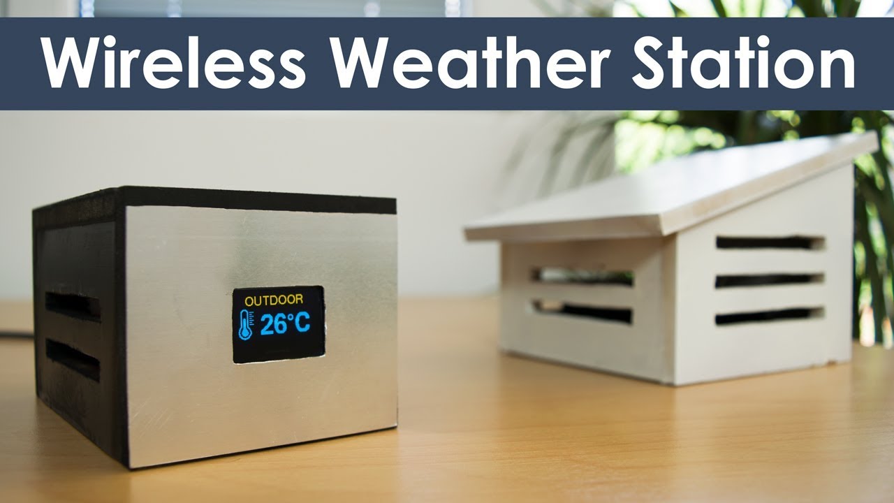
 In this tutorial we will learn how to make an Arduino based Wireless Weather
Station. You can watch the following video or read the written tutorial
below.
In this tutorial we will learn how to make an Arduino based Wireless Weather
Station. You can watch the following video or read the written tutorial
below.
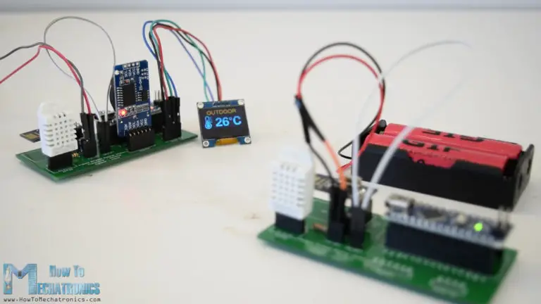
Overview The outdoor temperature and humidity are measured using the DHT22 sensor and this data is wirelessly sent to the indoor unit using the NRF24L01 transceiver modules. At the indoor unit, there is also another DHT22 sensor for measuring the indoor temperature and humidity, as well as a DS3231 Real Time Clock module which can keep track of the time even if the Arduino loses power. All of these data is printed on a 0.96” OLED display.
Arduino Wireless Weather Station Circuit Diagram Let’s take a look at the circuit diagram and how this project works. Note that I already have detailed tutorials on how each of these modules work, so for more details you can check them: NRF24L01 Tutorial, DHT22 Tutorial, DS3231 Tutorial .
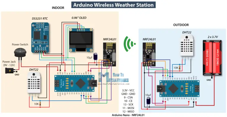 Arduino Wireless Weather Station Circuit Diagram
You can get the components needed for this project from the links below:
NRF24L01 Transceiver Module………. Amazon / Banggood / AliExpress
DHT22 Sensor…………….…………………… Amazon / Banggood /
AliExpress
DS3231 Real Time Clock………………….. Amazon / Banggood /
AliExpress
Arduino Nano ………………………….…….. Amazon / Banggood /
AliExpress
Disclosure: These are affiliate links. As an Amazon Associate I earn from
qualifying purchases.
Both the real time clock module and the OLED display use the I2C protocol
for communication with the Arduino so they are connected to the I2C pins or
the analog pins number 4 and 5 on the Arduino Nano board. Right next to the
NRF24L01 transceiver module there is a capacitor to keep the power supply to
it more stable. There is also a pull-up resistor connected to the DHT22 data
pin in order the sensor to work properly.
Ezoic
As for the power supply I used 12V DC power adapter for the indoor unit, and
on the other side, for powering the outdoor unit I used two Li-on batteries
producing around 7.5V. With this configuration the outdoor unit could run
for around 10 days before the batteries discharge, because we transmit data
periodically and in the meantime we put the Arduino to sleep mode, where the
power consumption is only around 7mA.
Custom design PCB
In order to keep the electronics components organized, according to the
circuit diagram I designed a custom PCB using the EasyEDA free online
circuit design software. We can note that the same PCB can be used for both
the indoor and the outdoor unit, only the Arduino board should be programmed
differently.
Arduino Wireless Weather Station Circuit Diagram
You can get the components needed for this project from the links below:
NRF24L01 Transceiver Module………. Amazon / Banggood / AliExpress
DHT22 Sensor…………….…………………… Amazon / Banggood /
AliExpress
DS3231 Real Time Clock………………….. Amazon / Banggood /
AliExpress
Arduino Nano ………………………….…….. Amazon / Banggood /
AliExpress
Disclosure: These are affiliate links. As an Amazon Associate I earn from
qualifying purchases.
Both the real time clock module and the OLED display use the I2C protocol
for communication with the Arduino so they are connected to the I2C pins or
the analog pins number 4 and 5 on the Arduino Nano board. Right next to the
NRF24L01 transceiver module there is a capacitor to keep the power supply to
it more stable. There is also a pull-up resistor connected to the DHT22 data
pin in order the sensor to work properly.
Ezoic
As for the power supply I used 12V DC power adapter for the indoor unit, and
on the other side, for powering the outdoor unit I used two Li-on batteries
producing around 7.5V. With this configuration the outdoor unit could run
for around 10 days before the batteries discharge, because we transmit data
periodically and in the meantime we put the Arduino to sleep mode, where the
power consumption is only around 7mA.
Custom design PCB
In order to keep the electronics components organized, according to the
circuit diagram I designed a custom PCB using the EasyEDA free online
circuit design software. We can note that the same PCB can be used for both
the indoor and the outdoor unit, only the Arduino board should be programmed
differently.
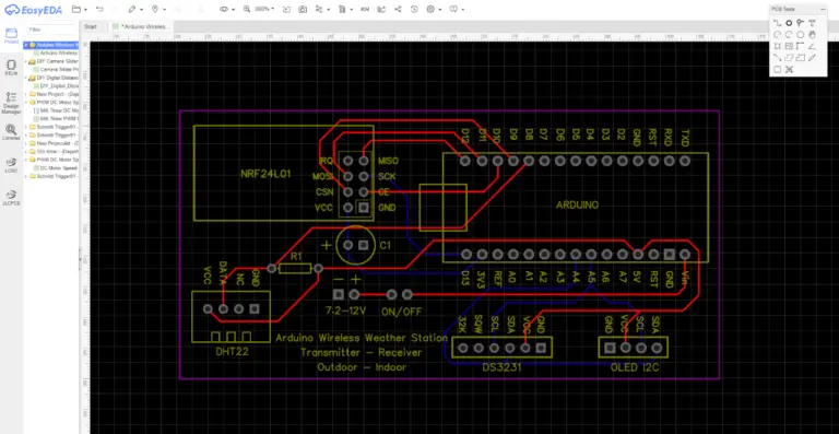 Arduino Weather Station custom PCB design
Once we finish the design here, we can simply export the Gerber file which
is used for manufacturing the PCB. You can check the EasyEDA project files
of Arduino wireless weather station here.
Then we can order our PCB from JLCPCB, which is actually the sponsor of this
video.
Arduino Weather Station custom PCB design
Once we finish the design here, we can simply export the Gerber file which
is used for manufacturing the PCB. You can check the EasyEDA project files
of Arduino wireless weather station here.
Then we can order our PCB from JLCPCB, which is actually the sponsor of this
video.
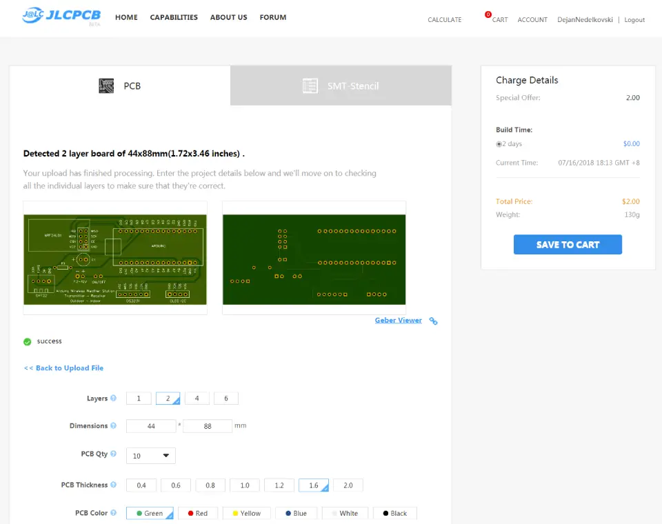
 Here we can simply drag and drop the Gerber file and once uploaded we can
review our PCB in the Gerber viewer. If everything is all right then we can
go on, select the properties that we want for our PCB, and then we can order
our PCB at a reasonable price. Note that if it’s your first order from
JLCPCB, you can get up to 10 PCBs for only $2.
Here we can simply drag and drop the Gerber file and once uploaded we can
review our PCB in the Gerber viewer. If everything is all right then we can
go on, select the properties that we want for our PCB, and then we can order
our PCB at a reasonable price. Note that if it’s your first order from
JLCPCB, you can get up to 10 PCBs for only $2.
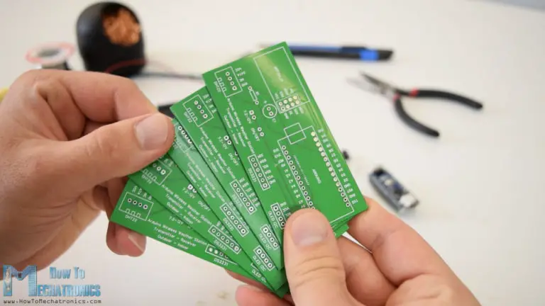
 Nevertheless, after several days the PCBs have arrived. The quality of the
PCBs is great and everything is exactly the same as in the design.
Nevertheless, after several days the PCBs have arrived. The quality of the
PCBs is great and everything is exactly the same as in the design.
 I started assembling the electronics components of this project by soldering
pin headers on to the PCB. In this way we can easily connect and disconnect
the components when needed.
I started assembling the electronics components of this project by soldering
pin headers on to the PCB. In this way we can easily connect and disconnect
the components when needed.
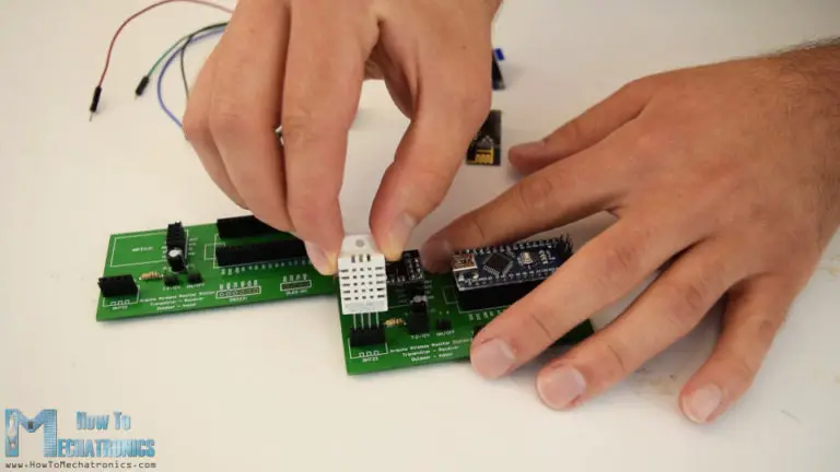
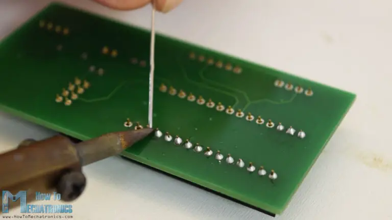 Then I also inserted and soldered the capacitor and the pull-up resistor.
With this step done, now we can simply attach the components onto the pin
headers of the PCB.
Then I also inserted and soldered the capacitor and the pull-up resistor.
With this step done, now we can simply attach the components onto the pin
headers of the PCB.
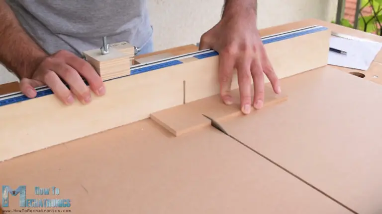
 Next, I moved on with making the cases for the project. For that purpose I
used 8mm tick MDF board and using a circular saw, I cut all pieces to size.
Next, I moved on with making the cases for the project. For that purpose I
used 8mm tick MDF board and using a circular saw, I cut all pieces to size.
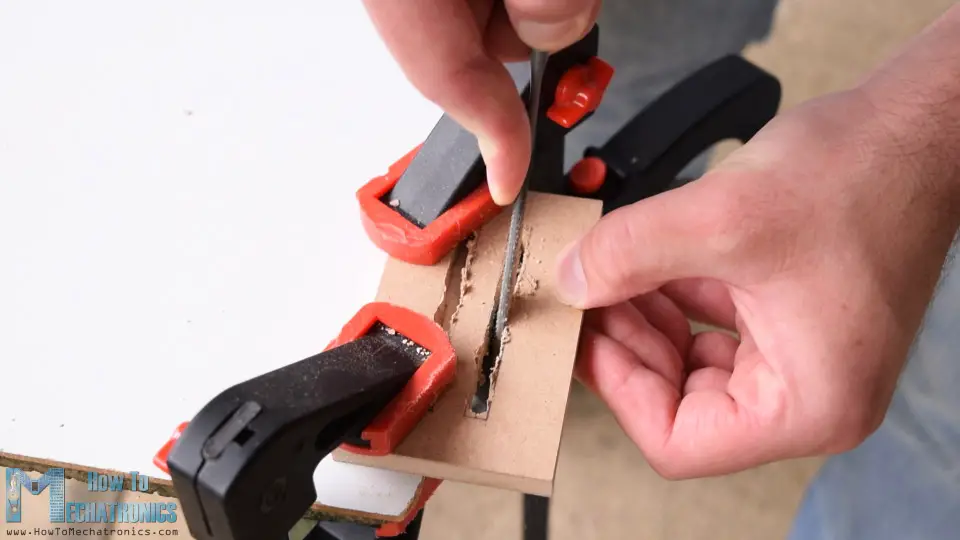
 In order to have accurate temperature and humidity measurements the sides of
the cases have to allow air to enter the case. So, using a drill and a rasp
I made several slots on the side panels on both the indoor and outdoor
units.
In order to have accurate temperature and humidity measurements the sides of
the cases have to allow air to enter the case. So, using a drill and a rasp
I made several slots on the side panels on both the indoor and outdoor
units.
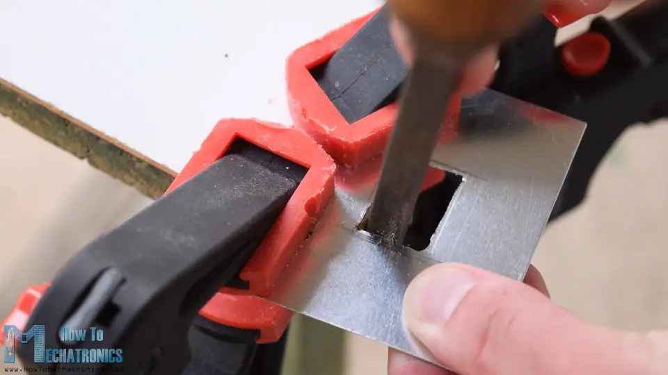
 I also made a slot for the OLED display on the front panel, as well as, cut
a small piece of aluminum to size which I will later attach on the front
panel as a decoration.
I also made a slot for the OLED display on the front panel, as well as, cut
a small piece of aluminum to size which I will later attach on the front
panel as a decoration.
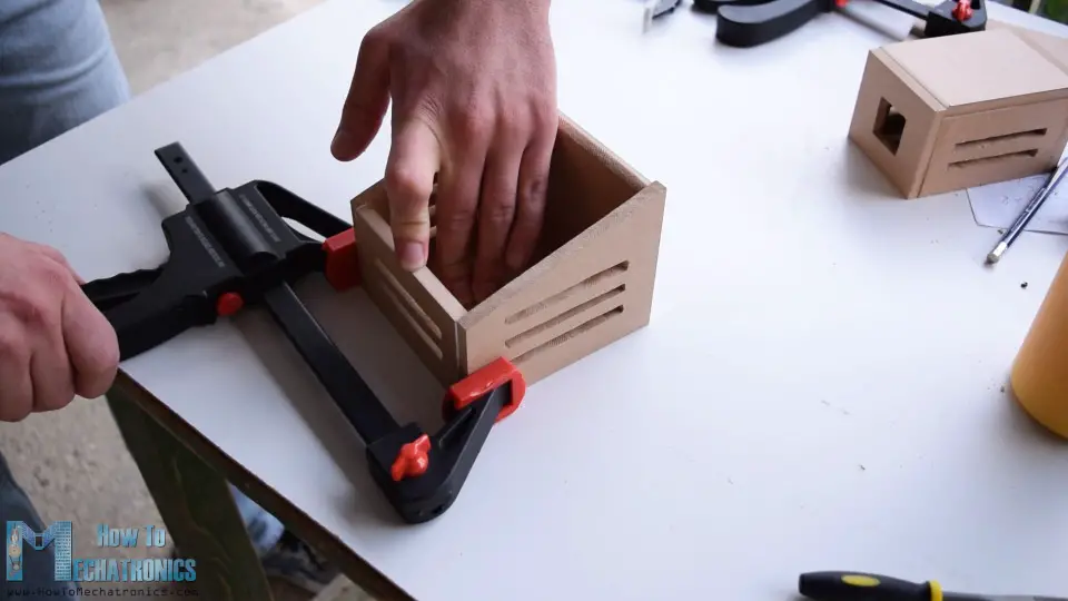
 For assembling the cases I used a wood glue and some clamps, as well as some
screws.
For assembling the cases I used a wood glue and some clamps, as well as some
screws.
 I painted the cases using a spray paint. I used white paint for the outdoor
unit and black one for the indoor unit. After the paint dried out, I simply
inserted the PCBs into the cases.
I painted the cases using a spray paint. I used white paint for the outdoor
unit and black one for the indoor unit. After the paint dried out, I simply
inserted the PCBs into the cases.
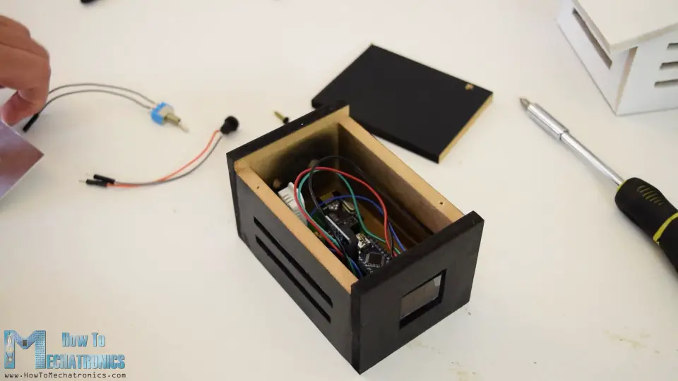 At the back side of the indoor unit I inserted a power jack and a power
switch, and at the outdoor unit I used a simple jumper wire as a power
switch.
At the back side of the indoor unit I inserted a power jack and a power
switch, and at the outdoor unit I used a simple jumper wire as a power
switch.
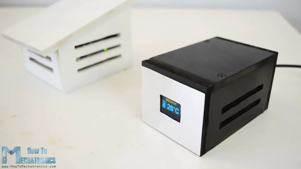 And that’s it, our Arduino wireless weather station is now working, but
what’s left in this video is to take a look how the program works.
Arduino Wireless Weather Station Code
And that’s it, our Arduino wireless weather station is now working, but
what’s left in this video is to take a look how the program works.
Arduino Wireless Weather Station Code
Arduino weather station outdoor unit code: /*H******************************************************* * Arduino Wireless Communication Tutorial Outdoor unit - Transmitter by Dejan Nedelkovski, www.HowToMechatronics.com Libraries: NRF24L01 - TMRh20/RF24, https://github.com/tmrh20/RF24/ DHT22 - DHTlib, https://github.com/RobTillaart/Ardui no/tree/master/libraries/DHTlib LowPower - https://github.com/rocketscream/Low-Power *********************************************************/ #include <SPI.h> #include <nRF24L01.h> #include <RF24.h> #include <dht.h> #include <LowPower.h> // **************** DEFINES **************************** #define dataPin 8 // DHT22 data pin // **************** PROTOTYPES ************************* // **************** VARIABLES ************************** dht DHT; // Creates a DHT object RF24 radio(10, 9); // CE, CSN const byte address[6] = "00001"; char thChar[32] = ""; String thString = ""; /*F******************************************************* * *********************************************************/ void setup() { radio.begin(); radio.openWritingPipe( address ); radio.setPALevel( RF24_PA_MIN ); radio.stopListening(); } /*F******************************************************* * *********************************************************/ void loop() { int readData = DHT.read22( dataPin ); // READS DATA FROM SENSOR int t = DHT.temperature; // GETS VALUES OF TEMPERATURE int h = DHT.humidity; // GETS VALUES OF HUMIDITY thString = String( t ) + String( h ); thString.toCharArray( thChar, 12 ); for( int i = 0; i <= 3; i++ ) // SENT DATA WIRELESSLY TO INDOOR UNIT { // SEND DATA 3 TIMES radio.write( &thChar, sizeof( thChar ) ); delay( 50 ); } // Sleep for 2 minutes, 15*8 = 120s for( int sleepCounter = 15; sleepCounter > 0; sleepCounter--) { LowPower.powerDown(SLEEP_8S, ADC_OFF, BOD_OFF); } } Code language: Arduino (arduino)
Description: The outdoor unit is the transmitter of the wireless communication, so here first we need to include the RF24 library, the DHT library, as well as the LowPower library which is used for putting the Arduino to sleep mode. After defining their instances, the pins to which the modules are connected and some variables, in the setup section we need to initialize the wireless communication address. Then in the loop section, first we read the data from the DHT22 sensor or that’s the temperature and humidity. Initially these values are integers and separated, so I convert them into a single String variable, put them in the character array, and using the radio.write() function, sent this data to the indoor unit. Using the for loop we send the data 3 times in order to be sure that the receiver will get data in case the controller is busy at the time of sending. At the end we put the Arduino to sleep mode for a particular period of time in order to minimize the power consumption. /*H******************************************************* * Arduino weather station indoor unit code: Arduino Wireless Communication Tutorial Indoor unit - Receiver by Dejan Nedelkovski, www.HowToMechatronics.com Libraries: DS3231 - http://www.rinkydinkelectronics.com/library.php?id=73 U8G2 - https://github.com/olikraus/u8g2 *********************************************************/ #include <SPI.h> #include <nRF24L01.h> #include <RF24.h> #include <dht.h> #include <DS3231.h> #include <U8g2lib.h> #include <Wire.h> // **************** DEFINES **************************** #define dataPin 8 // DHT22 sensor #define Temperature_20Icon_width 27 #define Temperature_20Icon_height 47 static const unsigned char Temperature_20Icon_bits[] U8X8_PROGMEM = { 0x00, 0x00, 0x00, 0x00, 0x00, 0x3f, 0x00, 0x00, 0x80, 0x7f, 0x00, 0x00, 0xc0, 0xe1, 0x00, 0x00, 0xe0, 0xc0, 0x01, 0x00, 0x60, 0x80, 0xf9, 0x03, 0x60, 0x80, 0x01, 0x00, 0x60, 0x80, 0x01, 0x00, 0x60, 0x80, 0x79, 0x00, 0x60, 0x80, 0x01, 0x00, 0x60, 0x80, 0x01, 0x00, 0x60, 0x80, 0xf9, 0x03, 0x60, 0x80, 0x01, 0x00, 0x60, 0x80, 0x01, 0x00, 0x60, 0x8c, 0x79, 0x00, 0x60, 0x9e, 0x01, 0x00, 0x60, 0x9e, 0x01, 0x00, 0x60, 0x9e, 0xf9, 0x03, 0x60, 0x9e, 0x01, 0x00, 0x60, 0x9e, 0x01, 0x00, 0x60, 0x9e, 0x79, 0x00, 0x60, 0x9e, 0x01, 0x00, 0x60, 0x9e, 0x01, 0x00, 0x60, 0x9e, 0xf9, 0x03, 0x60, 0x9e, 0x01, 0x00, 0x60, 0x9e, 0x01, 0x00, 0x60, 0x9e, 0x01, 0x00, 0x70, 0x9e, 0x03, 0x00, 0x38, 0x1e, 0x07, 0x00, 0x18, 0x3e, 0x0e, 0x00, 0x1c, 0x3f, 0x0c, 0x00, 0x0c, 0x7f, 0x18, 0x00, 0x8c, 0xff, 0x18, 0x00, 0x8e, 0xff, 0x38, 0x00, 0xc6, 0xff, 0x31, 0x00, 0xc6, 0xff, 0x31, 0x00, 0xc6, 0xff, 0x31, 0x00, 0x8e, 0xff, 0x38, 0x00, 0x8c, 0xff, 0x18, 0x00, 0x0c, 0x7f, 0x1c, 0x00, 0x3c, 0x1c, 0x0e, 0x00, 0x78, 0x00, 0x06, 0x00, 0xe0, 0x80, 0x07, 0x00, 0xe0, 0xff, 0x03, 0x00, 0x80, 0xff, 0x00, 0x00, 0x00, 0x1c, 0x00, 0x00, 0x00, 0x00, 0x00, 0x00 }; #define Humidity_20Icon_width 27 #define Humidity_20Icon_height 47 static const unsigned char Humidity_20Icon_bits[] U8X8_PROGMEM = { 0x00, 0x00, 0x00, 0x00, 0x00, 0x70, 0x00, 0x00, 0x00, 0x70, 0x00, 0x00, 0x00, 0x70, 0x00, 0x00, 0x00, 0xf8, 0x00, 0x00, 0x00, 0xdc, 0x00, 0x00, 0x00, 0xdc, 0x01, 0x00, 0x00, 0x8e, 0x01, 0x00, 0x00, 0x86, 0x03, 0x00, 0x00, 0x06, 0x03, 0x00, 0x00, 0x03, 0x07, 0x00, 0x80, 0x03, 0x06, 0x00, 0x80, 0x01, 0x0c, 0x00, 0xc0, 0x01, 0x1c, 0x00, 0xc0, 0x00, 0x18, 0x00, 0xe0, 0x00, 0x38, 0x00, 0x60, 0x00, 0x30, 0x00, 0x70, 0x00, 0x70, 0x00, 0x30, 0x00, 0xe0, 0x00, 0x38, 0x00, 0xc0, 0x00, 0x18, 0x00, 0xc0, 0x01, 0x1c, 0x00, 0x80, 0x01, 0x0c, 0x00, 0x80, 0x03, 0x0e, 0x00, 0x80, 0x03, 0x06, 0x00, 0x00, 0x03, 0x06, 0x00, 0x00, 0x03, 0x07, 0x00, 0x00, 0x07, 0x03, 0x00, 0x00, 0x06, 0x03, 0x00, 0x00, 0x06, 0x03, 0x00, 0x00, 0x06, 0x63, 0x00, 0x00, 0x06, 0x63, 0x00, 0x00, 0x06, 0x63, 0x00, 0x00, 0x06, 0xe3, 0x00, 0x00, 0x06, 0xc7, 0x00, 0x00, 0x06, 0xc6, 0x01, 0x00, 0x07, 0x86, 0x03, 0x00, 0x03, 0x0e, 0x1f, 0x00, 0x03, 0x0e, 0x1e, 0x80, 0x01, 0x1c, 0x00, 0xc0, 0x01, 0x38, 0x00, 0xe0, 0x00, 0x78, 0x00, 0x70, 0x00, 0xf0, 0x00, 0x38, 0x00, 0xe0, 0x07, 0x1f, 0x00, 0x80, 0xff, 0x0f, 0x00, 0x00, 0xff, 0x03, 0x00, 0x00, 0x00, 0x00, 0x00 }; // **************** PROTOTYPES ************************* void drawDate(); void drawInTemperature(); void drawInHumidity(); void drawOutTemperature(); void drawOutHumidity(); // **************** VARIABLES ************************** dht DHT; // Creats DHT object DS3231 rtc( SDA, SCL ); U8G2_SSD1306_128X64_NONAME_1_HW_I2C u8g2( U8G2_R0, U8X8_PIN_NONE);// RESET= RF24 radio(10, 9); // CE, CSN const byte address[6] = "00001"; char text[6] = ""; int readDHT22, t, h; String inTemp, inHum, outTemp, outHum; String rtcTime, rtcDate; int draw_state = 0; unsigned long previousMillis = 0; long interval = 3000; /*F******************************************************* * *********************************************************/ void setup() { radio.begin(); radio.openReadingPipe( 0, address ); radio.setPALevel( RF24_PA_MIN ); radio.startListening(); u8g2.begin(); rtc.begin(); } /*F******************************************************* * *********************************************************/ void loop() { if( radio.available()) { radio.read( &text, sizeof( text ) ); // READ INCOMING DATA // OUTDOOR Temp outTemp = String(text[0]) + String(text[1]) + char(176) + "C"; outHum = String(text[2]) + String(text[3]) + "%"; // Outdoor Humidity } unsigned long currentMillis = millis(); if( currentMillis - previousMillis > interval) { previousMillis = currentMillis; u8g2.firstPage(); do { switch( draw_state ) { case 0: drawDate(); break; case 1: drawInTemperature(); break; case 2: drawInHumidity(); break; case 3: drawOutTemperature(); break; case 4: drawOutHumidity(); break; } }while( u8g2.nextPage() ); draw_state++; if( draw_state > 4) { draw_state = 0; } } } /*F******************************************************* * *********************************************************/ void drawDate() { String dowa = rtc.getDOWStr(); dowa.remove( 3 ); rtcDate = dowa + " " + rtc.getDateStr(); u8g2.setFont( u8g2_font_timB14_tr ); u8g2.setCursor( 0, 15 ); rtcTime = rtc.getTimeStr(); // DS3231 RTC TIME rtcTime.remove( 5 ); u8g2.print( rtcDate ); u8g2.setFont( u8g2_font_fub30_tf ); u8g2.setCursor( 8, 58 ); u8g2.print( rtcTime ); } /*F******************************************************* * *********************************************************/ void drawInTemperature() { readDHT22 = DHT.read22( dataPin ); // READS DATA FROM SENSOR t = DHT.temperature; // GETS VALUES OF TEMPERATURE inTemp = String(t) + char(176) + "C"; u8g2.setFont( u8g2_font_helvR14_tr ); u8g2.setCursor( 24, 15 ); u8g2.print( "INDOOR" ); u8g2.setFont( u8g2_font_fub30_tf ); u8g2.setCursor( 36, 58 ); u8g2.print( inTemp ); u8g2.drawXBMP( 0, 17, Temperature_20Icon_width, Temperature_20Icon_height , Temperature_20Icon_bits); } /*F******************************************************* * *********************************************************/ void drawInHumidity() { h = DHT.humidity; // GETS VALUES OF HUMIDITY inHum = String( h ) + "%"; u8g2.setFont( u8g2_font_helvR14_tr ); u8g2.setCursor( 24, 15 ); u8g2.print( "INDOOR" ); u8g2.setFont( u8g2_font_fub30_tf ); u8g2.setCursor( 36, 58 ); u8g2.print( inHum ); u8g2.drawXBMP( 0, 17, Humidity_20Icon_width, Humidity_20Icon_height , Humidity_20Icon_bits); } /*F******************************************************* * *********************************************************/ void drawOutTemperature() { u8g2.setFont( u8g2_font_helvR14_tr ); u8g2.setCursor( 12, 15 ); u8g2.print( "OUTDOOR" ); u8g2.setFont( u8g2_font_fub30_tf ); u8g2.setCursor( 36, 58 ); u8g2.print( outTemp ); u8g2.drawXBMP( 0, 17, Temperature_20Icon_width, Temperature_20Icon_height , Temperature_20Icon_bits); } /*F******************************************************* * *********************************************************/ void drawOutHumidity() { u8g2.setFont( u8g2_font_helvR14_tr ); u8g2.setCursor( 12, 15 ); u8g2.print( "OUTDOOR" ); u8g2.setFont( u8g2_font_fub30_tf ); u8g2.setCursor( 36, 58 ); u8g2.print( outHum ); u8g2.drawXBMP( 0, 17, Humidity_20Icon_width, Humidity_20Icon_height , Humidity_20Icon_bits); }
Description: On the other side, at the indoor unit or the receiver, we need to include two more libraries, one for the DS3231 real time clock module and one for the OLED display, the U8G2 library. In the same way as previously, we need to define the instances, the pins and some variables need for the program below. Also here we need to define the temperature and humidity icons as bitmaps.
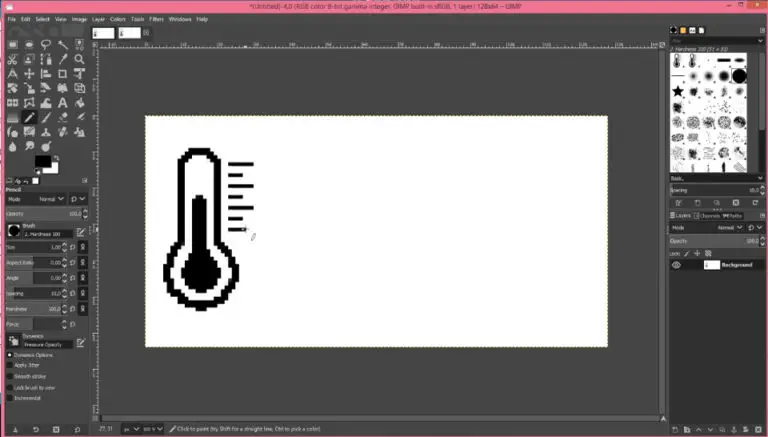
Temperature icon bitmap: #define Temperature_20Icon_width 27 #define Temperature_20Icon_height 47 static const unsigned char Temperature_20Icon_bits[] U8X8_PROGMEM = { 0x00, 0x00, 0x00, 0x00, 0x00, 0x3f, 0x00, 0x00, 0x80, 0x7f, 0x00, 0x00, 0xc0, 0xe1, 0x00, 0x00, 0xe0, 0xc0, 0x01, 0x00, 0x60, 0x80, 0xf9, 0x03, 0x60, 0x80, 0x01, 0x00, 0x60, 0x80, 0x01, 0x00, 0x60, 0x80, 0x79, 0x00, 0x60, 0x80, 0x01, 0x00, 0x60, 0x80, 0x01, 0x00, 0x60, 0x80, 0xf9, 0x03, 0x60, 0x80, 0x01, 0x00, 0x60, 0x80, 0x01, 0x00, 0x60, 0x8c, 0x79, 0x00, 0x60, 0x9e, 0x01, 0x00, 0x60, 0x9e, 0x01, 0x00, 0x60, 0x9e, 0xf9, 0x03, 0x60, 0x9e, 0x01, 0x00, 0x60, 0x9e, 0x01, 0x00, 0x60, 0x9e, 0x79, 0x00, 0x60, 0x9e, 0x01, 0x00, 0x60, 0x9e, 0x01, 0x00, 0x60, 0x9e, 0xf9, 0x03, 0x60, 0x9e, 0x01, 0x00, 0x60, 0x9e, 0x01, 0x00, 0x60, 0x9e, 0x01, 0x00, 0x70, 0x9e, 0x03, 0x00, 0x38, 0x1e, 0x07, 0x00, 0x18, 0x3e, 0x0e, 0x00, 0x1c, 0x3f, 0x0c, 0x00, 0x0c, 0x7f, 0x18, 0x00, 0x8c, 0xff, 0x18, 0x00, 0x8e, 0xff, 0x38, 0x00, 0xc6, 0xff, 0x31, 0x00, 0xc6, 0xff, 0x31, 0x00, 0xc6, 0xff, 0x31, 0x00, 0x8e, 0xff, 0x38, 0x00, 0x8c, 0xff, 0x18, 0x00, 0x0c, 0x7f, 0x1c, 0x00, 0x3c, 0x1c, 0x0e, 0x00, 0x78, 0x00, 0x06, 0x00, 0xe0, 0x80, 0x07, 0x00, 0xe0, 0xff, 0x03, 0x00, 0x80, 0xff, 0x00, 0x00, 0x00, 0x1c, 0x00, 0x00, 0x00, 0x00, 0x00, 0x00 }; Code language: Arduino (arduino) For this purpose we can use GIMP, an open source image editor, through which we can draw anything and then export it as bitmap(.xbm).
 Then we can open this file using a notepad and from there we can copy the
bitmap into the Arduino code.
Note that here we can define the bitmap as constant using the PROGMEM
variable modifier, and it that way the bitmap will be stored in the flash
memory instead of the SRAM of the Arduino board.
static const unsigned char Temperature_20Icon_bits[] U8X8_PROGMEM // Save in
the Flash memory
static unsigned char Temperature_20Icon_bits[] // Save in the SRAM
In the setup section we need to initialize the wireless communication as
well as initialize the OLED display and the real time clock module.
Then in the loop section we constantly check whether there is an incoming
data available to be read via the NRF24L01 modules. If true, using the
radio.read() function we read it, and store the first two characters into
the temperature String variable, and the next two characters into the
humidity String variable.
Then we use the millis() function in order to display the various data on
the display at intervals defined with the interval variable which I set it
to 3 seconds. We are using the millis() function because in this way the
rest of the code can be repeatedly executed, while in case we use the
delay() function, the program waits for that period so in that way we would
probably miss the incoming data from the outdoor unit.
Next, using the firstPage() and nextPage() function of the U8G2 library we
print the five different screens which are defined with the custom
functions.
ADVERTISING
Ezoic
The drawDate() custom function gets the date and time information from the
real time clock module and prints it on the display appropriately. The
drawInTemperature() function reads the indoor temperature and prints it
appropriately on the display. In fact, the same method is used for printing
all of the screens on the display.
So that would be all, I hope you enjoyed this Arduino project and learned
something new. Feel free to ask any question in the comments section below
Then we can open this file using a notepad and from there we can copy the
bitmap into the Arduino code.
Note that here we can define the bitmap as constant using the PROGMEM
variable modifier, and it that way the bitmap will be stored in the flash
memory instead of the SRAM of the Arduino board.
static const unsigned char Temperature_20Icon_bits[] U8X8_PROGMEM // Save in
the Flash memory
static unsigned char Temperature_20Icon_bits[] // Save in the SRAM
In the setup section we need to initialize the wireless communication as
well as initialize the OLED display and the real time clock module.
Then in the loop section we constantly check whether there is an incoming
data available to be read via the NRF24L01 modules. If true, using the
radio.read() function we read it, and store the first two characters into
the temperature String variable, and the next two characters into the
humidity String variable.
Then we use the millis() function in order to display the various data on
the display at intervals defined with the interval variable which I set it
to 3 seconds. We are using the millis() function because in this way the
rest of the code can be repeatedly executed, while in case we use the
delay() function, the program waits for that period so in that way we would
probably miss the incoming data from the outdoor unit.
Next, using the firstPage() and nextPage() function of the U8G2 library we
print the five different screens which are defined with the custom
functions.
ADVERTISING
Ezoic
The drawDate() custom function gets the date and time information from the
real time clock module and prints it on the display appropriately. The
drawInTemperature() function reads the indoor temperature and prints it
appropriately on the display. In fact, the same method is used for printing
all of the screens on the display.
So that would be all, I hope you enjoyed this Arduino project and learned
something new. Feel free to ask any question in the comments section below