Numerically Controlled Oscillator
From: https://en.wikipedia.org/wiki/Numerically_controlled_oscillator
Numerically controlled oscillator

From Wikipedia, the free encyclopedia
(Redirected from Numerically-controlled oscillator)
A numerically controlled oscillator (NCO) is a digital
signal generator which creates a synchronous (i.e., clocked), discrete-time,
discrete-valued representation of a waveform, usually sinusoidal.[1] NCOs are
often used in conjunction with a digital-to-analog converter (DAC) at the output
to create a direct digital synthesizer (DDS).[3]

Numerically controlled oscillators offer several advantages over other types of
oscillators in terms of agility, accuracy, stability and reliability.[2] NCOs
are used in many communications systems including digital up/down converters
used in 3G wireless and software radio systems, digital phase-locked loops,
radar systems, drivers for optical or acoustic transmissions, and multilevel
FSK/PSK modulators/demodulators.[2]


Operation
An NCO generally consists of two parts:
- A phase accumulator (PA), which adds to the value held at its output a
frequency control value at each clock sample.
- A phase-to-amplitude converter (PAC), which uses the phase accumulator
output word (phase word) usually as an index into a waveform look-up table
(LUT) to provide a corresponding amplitude sample. Sometimes interpolation
is used with the look-up table to provide better accuracy and reduce phase
error noise. Other methods of converting phase to amplitude, including
mathematical algorithms such as power series can be used, particularly in a
software NCO.
|
|
|
When clocked, the phase accumulator (PA) creates a modulo-2N sawtooth
waveform which is then converted by the phase-to-amplitude converter (PAC)
to a sampled sinusoid, where N is the number of bits carried in the phase
accumulator. N sets the NCO frequency resolution and is normally much larger
than the number of bits defining the memory space of the PAC look-up table.
If the PAC capacity is 2M, the PA output word must be truncated to M bits as
shown in Figure 1. However, the truncated bits can be used for
interpolation. The truncation of the phase output word does not affect the
frequency accuracy but produces a time-varying periodic phase error which is
a primary source of spurious products. Another spurious product generation
mechanism is finite word length effects of the PAC output (amplitude)
word.[4]
|
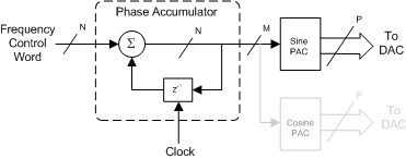 Figure 1: Numerically controlled oscillator with optional quadrature output
|
The frequency accuracy relative to the clock frequency is limited only by the
precision of the arithmetic used to compute the phase.[4] NCOs are phase - and
frequency-agile, and can be trivially modified to produce a phase-modulated or
frequency-modulated output by summation at the appropriate node, or provide
quadrature outputs as shown in the figure.
Phase accumulator
A binary phase accumulator consists of an N-bit binary adder and a register
configured as shown in Figure 1.[5] Each clock cycle produces a new N-bit
output consisting of the previous output obtained from the register summed
with the frequency control word (FCW) which is constant for a given output
frequency. The resulting output waveform is a staircase with step size Δ F
\Delta F, the integer value of the FCW.[6] In some configurations, the phase
output is taken from the output of the register which introduces a one clock
cycle latency but allows the adder to operate at a higher clock rate.[2]
|
|
|---|
The adder is designed to overflow when the sum of the absolute value of its
operands exceeds its capacity (2N−1). The overflow bit is discarded so the
output word width is always equal to its input word width. The remainder ϕ
n \phi _{n}, called the residual, is stored in the register and the cycle
repeats, starting this time from ϕ n \phi _{n} (see figure 2).[5] Since a
phase accumulator is a finite state machine, eventually the residual at some
sample K must return to the initial value ϕ 0 \phi _{0}. The interval K is
referred to as the grand repetition rate (GRR) given by
 where GCD is the greatest common divisor function. The GRR represents the
true periodicity for a given Δ F \Delta F which for a high resolution NCO
can be very long.[5]
where GCD is the greatest common divisor function. The GRR represents the
true periodicity for a given Δ F \Delta F which for a high resolution NCO
can be very long.[5]
|
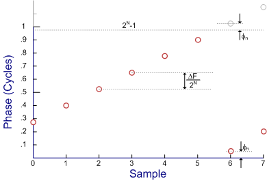 Figure 2: Normalized phase accumulator output
|
Usually we are more interested in the operating frequency determined by the
average overflow rate, given by[6]
 The frequency resolution, defined as the smallest possible incremental
change in frequency, is given by[6]
The frequency resolution, defined as the smallest possible incremental
change in frequency, is given by[6]
 Equation (1) shows that the phase accumulator can be thought of as a
programmable non-integer frequency divider of divide ratio Δ F / 2 N
Equation (1) shows that the phase accumulator can be thought of as a
programmable non-integer frequency divider of divide ratio Δ F / 2 N
Phase-to-amplitude converter
The phase-amplitude converter creates the sample-domain waveform from the
truncated phase output word received from the PA. The PAC can be a simple
read only memory containing 2M contiguous samples of the desired output
waveform which typically is a sinusoid. Often though, various tricks are
employed to reduce the amount of memory required. This include various
trigonometric expansions,[7] trigonometric approximations[5] and methods
which take advantage of the quadrature symmetry exhibited by sinusoids.[8]
Alternatively, the PAC may consist of random access memory which can be
filled as desired to create an arbitrary waveform generator.
Spurious products
Spurious products are the result of harmonic or non-harmonic distortion in
the creation of the output waveform due to non-linear numerical effects in
the signal processing chain. Only numerical errors are covered here. For
other distortion mechanisms created in the digital-to-analog converter see
the corresponding section in the direct-digital synthesizer article.
Phase truncation spurs
The number of phase accumulator bits of an NCO (N) is usually between 16 and
64. If the PA output word were used directly to index the PAC look-up table
an untenably high storage capacity in the ROM would be required. As such,
the PA output word must be truncated to span a reasonable memory space.
Truncation of the phase word causes phase modulation of the output sinusoid
which introduces non-harmonic distortion in proportion to the number of bits
truncated. The number of spurious products created by this distortion is
given by:
 where W is the number of bits truncated.
In calculating the spurious-free dynamic range, we are interested in the
spurious product with the largest amplitude relative to the carrier output
level given by:
where W is the number of bits truncated.
In calculating the spurious-free dynamic range, we are interested in the
spurious product with the largest amplitude relative to the carrier output
level given by:
 where P is the size of the phase-to-amplitude converter's lookup table in
bits, i.e., M in Figure 1. For W >4,
where P is the size of the phase-to-amplitude converter's lookup table in
bits, i.e., M in Figure 1. For W >4,
 Another related spurious generation method is the slight modulation due to
the GRR outlined above. The amplitude of these spurs is low for large N and
their frequency is generally too low to be detectable but they may cause
issues for some applications.[5]
One way to reduce the truncation in the address lookup is to have several
smaller lookup tables in parallel and use the upper bits to index into the
tables and the lower bits to weigh them for linear or quadratic
interpolation. Ie use a 24-bit phase accumulator to look up into two 16-bit
LUTS. Address into the truncated 16 MSBs, and that plus 1. Linearly
interpolate using the 8 LSBs as weights. (One could instead use 3 LUTs
instead and quadratically interpolate). This can result in decreased
distortion for the same amount of memory at the cost of some multipliers.
Another related spurious generation method is the slight modulation due to
the GRR outlined above. The amplitude of these spurs is low for large N and
their frequency is generally too low to be detectable but they may cause
issues for some applications.[5]
One way to reduce the truncation in the address lookup is to have several
smaller lookup tables in parallel and use the upper bits to index into the
tables and the lower bits to weigh them for linear or quadratic
interpolation. Ie use a 24-bit phase accumulator to look up into two 16-bit
LUTS. Address into the truncated 16 MSBs, and that plus 1. Linearly
interpolate using the 8 LSBs as weights. (One could instead use 3 LUTs
instead and quadratically interpolate). This can result in decreased
distortion for the same amount of memory at the cost of some multipliers.
Amplitude truncation spurs
Another source of spurious products is the amplitude quantization of the
sampled waveform contained in the PAC look up table(s). If the number of DAC
bits is P, the AM spur level is approximately equal to −6.02 P − 1.76
dBc.[9]
Mitigation techniques
Phase truncation spurs can be reduced substantially by the introduction of
white gaussian noise prior to truncation. The so-called dither noise is
summed into the lower W+1 bits of the PA output word to linearize the
truncation operation. Often the improvement can be achieved without penalty
because the DAC noise floor tends to dominate system performance. Amplitude
truncation spurs can not be mitigated in this fashion. Introduction of noise
into the static values held in the PAC ROMs would not eliminate the
cyclicality of the truncation error terms and thus would not achieve the
desired effect.[4]
See also