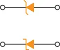
 zener diode schematic symbols
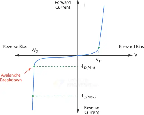
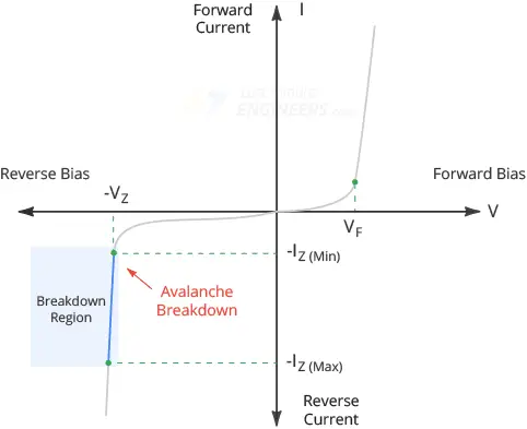
Zener Diode Working A zener diode can operate in any of three regions: forward, leakage, and breakdown. Let’s understand this through the I-V graph of a zener diode.
 zener diode iv characteristics
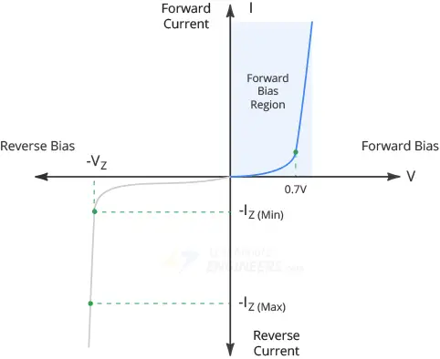
Forward Bias Region When forward-biased, Zener diodes behave much the same as ordinary silicon diodes and start conducting at around 0.7V
 zener diode forward bias region
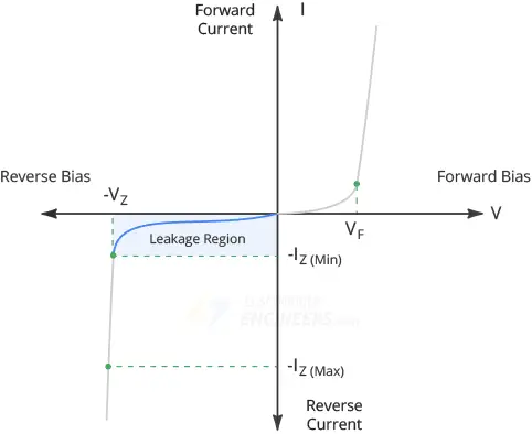
Leakage Region The leakage region exists between zero current and breakdown. In the leakage region, a small reverse current flows through the diode. This reverse current is caused by the thermally produced minority carriers.
 zener diode leakage region
Breakdown Region If you continue increasing the reverse voltage, you will eventually reach the so-called Zener voltage VZ of the diode. At this point, a process called Avalanche Breakdown occurs in the semiconductor depletion layer and the diode starts conducting heavily in the reverse direction.
 zener diode breakdown region
You can see from the graph that the breakdown has a very sharp knee, followed by
an almost vertical increase in current. Note that the voltage across the zener
diode is almost constant and approximately equal to VZ over most of the
breakdown region.
The graph also shows the maximum reverse current IZ(Max). As long as the reverse
current is less than IZ(Max), the diode operates within its safe range. If the
current exceeds IZ(Max), the diode will be destroyed.
zener diode breakdown region
You can see from the graph that the breakdown has a very sharp knee, followed by
an almost vertical increase in current. Note that the voltage across the zener
diode is almost constant and approximately equal to VZ over most of the
breakdown region.
The graph also shows the maximum reverse current IZ(Max). As long as the reverse
current is less than IZ(Max), the diode operates within its safe range. If the
current exceeds IZ(Max), the diode will be destroyed.
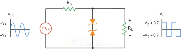
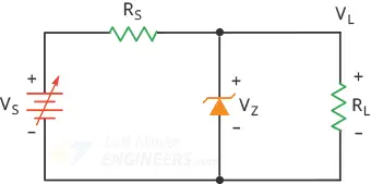
Zener Voltage Regulator The Zener diode maintains a constant output voltage in the breakdown region, even though the current through it varies. This is an important feature of the zener diode, which can be used in voltage regulator applications. Therefore a zener diode is sometimes called a Voltage-regulator diode. For example, the output of half-wave, full-wave or bridge rectifiers consists of ripples superimposed on a DC voltage. By connecting a simple zener diode across the output of the rectifier, we can obtain a more stable DC output voltage. The following figure shows a simple zener voltage regulator (also known as a zener regulator).
 zener diode as a voltage regulator
To operate the zener diode in its breakdown condition, the zener diode is
reverse biased by connecting its cathode to the positive terminal of the
input supply.
A series (current-limiting) resistor RS is connected in series with the
zener diode so that the current flowing through the diode is less than its
maximum current rating. Otherwise, the zener diode will burn out, like any
device because of too much power dissipation.
The voltage source VS is connected across the combination. Also, to keep the
diode in its breakdown condition, the source voltage VS must be greater than
the zener breakdown voltage VZ.
The stabilized output voltage Vout is taken from across the zener diode.
zener diode as a voltage regulator
To operate the zener diode in its breakdown condition, the zener diode is
reverse biased by connecting its cathode to the positive terminal of the
input supply.
A series (current-limiting) resistor RS is connected in series with the
zener diode so that the current flowing through the diode is less than its
maximum current rating. Otherwise, the zener diode will burn out, like any
device because of too much power dissipation.
The voltage source VS is connected across the combination. Also, to keep the
diode in its breakdown condition, the source voltage VS must be greater than
the zener breakdown voltage VZ.
The stabilized output voltage Vout is taken from across the zener diode.
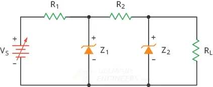
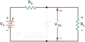
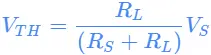
Breakdown Operation To test whether the zener diode is operating in the breakdown region, we need to calculate how much Thevenin voltage the diode is facing. Thevenin voltage is the voltage that exists when the zener diode is disconnected from the circuit.
 calculating thevenin voltage facing zener diode
Because of the voltage divider, we can write:
calculating thevenin voltage facing zener diode
Because of the voltage divider, we can write:
 zener_1
When this voltage exceeds the zener voltage, breakdown occurs.
zener_1
When this voltage exceeds the zener voltage, breakdown occurs.
Series Current
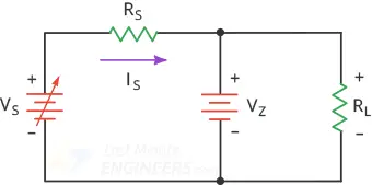 zener diode series current
The voltage across the series resistor equals the difference between the
source voltage and the zener voltage. Therefore, according to the Ohm’s
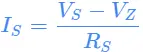
law, the current through the series resistor is:
zener diode series current
The voltage across the series resistor equals the difference between the
source voltage and the zener voltage. Therefore, according to the Ohm’s
law, the current through the series resistor is:
 zener_2
The series current remains the same whether or not there is a load resistor.
Meaning, even if you disconnect the load resistor, the current through the
series resistor will be equal to the voltage across the resistor divided by the
resistance.
zener_2
The series current remains the same whether or not there is a load resistor.
Meaning, even if you disconnect the load resistor, the current through the
series resistor will be equal to the voltage across the resistor divided by the
resistance.
Load Voltage and Load Current
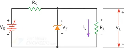 zener diode load voltage and load current
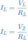
Because the load resistor is in parallel with the zener diode, the load voltage
is the same as the Zener voltage.
zener diode load voltage and load current
Because the load resistor is in parallel with the zener diode, the load voltage
is the same as the Zener voltage.
 zener_3
Using the Ohm’s law, we can calculate the load current:
zener_3
Using the Ohm’s law, we can calculate the load current:
 zener_4
zener current
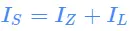
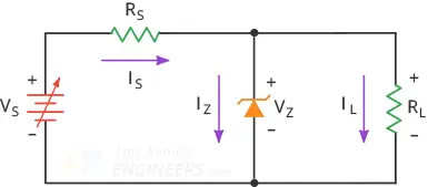 The zener diode and the load resistor are in parallel. The total current is
equal to the sum of their currents, which is the same as the current through the
series resistor.
The zener diode and the load resistor are in parallel. The total current is
equal to the sum of their currents, which is the same as the current through the
series resistor.
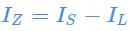
 zener_5
This tells us that, the zener current equals the series current minus the load
current.
zener_5
This tells us that, the zener current equals the series current minus the load
current.
 zener_6
Common Zener Diode Voltages Zener diodes are manufactured in standard voltage ratings listed in Table below. The table lists common voltages for 0.3W and 1.3W parts.