Series Parallel Ckts
From: https://www.allaboutcircuits.com/textbook/alternating-current/chpt-6/resonance-series-parallel-circuits/
Resonance in Series-Parallel Circuits
In simple reactive circuits with little or no resistance, the effects of
radically altered impedance will manifest at the resonance frequency
predicted by the equation given earlier. In a parallel (tank) LC circuit,
this means infinite impedance at resonance. In a series LC circuit, it means
zero impedance at resonance:
 However, as soon as significant levels of resistance are introduced into
most LC circuits, this simple calculation for resonance becomes invalid.
On this page, we’ll take a look at several LC circuits with added
resistance, using the same values for capacitance and inductance as before:
10 µF and 100 mH, respectively.
However, as soon as significant levels of resistance are introduced into
most LC circuits, this simple calculation for resonance becomes invalid.
On this page, we’ll take a look at several LC circuits with added
resistance, using the same values for capacitance and inductance as before:
10 µF and 100 mH, respectively.
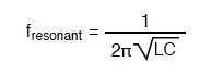
Calculating the Resonant Frequency
of a High-Resistance Circuit
According to our simple equation above, the resonant frequency should be
159.155 Hz. Watch, though, where current reaches maximum or minimum in the
following SPICE analyses:
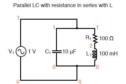 Parallel LC circuit with resistance in series with L.
resonant circuit
v1 1 0 ac 1 sin
c1 1 0 10u
r1 1 2 100
l1 2 0 100m
.ac lin 20 100 200
.plot ac i(v1)
.end
Results:
Parallel LC circuit with resistance in series with L.
resonant circuit
v1 1 0 ac 1 sin
c1 1 0 10u
r1 1 2 100
l1 2 0 100m
.ac lin 20 100 200
.plot ac i(v1)
.end
Results:
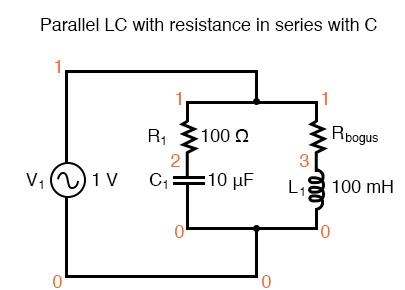
 Resistance in series with L produces minimum current at 136.8 Hz instead of
calculated 159.2 Hz
Minimum current at 136.8 Hz instead of 159.2 Hz!
Resistance in series with L produces minimum current at 136.8 Hz instead of
calculated 159.2 Hz
Minimum current at 136.8 Hz instead of 159.2 Hz!
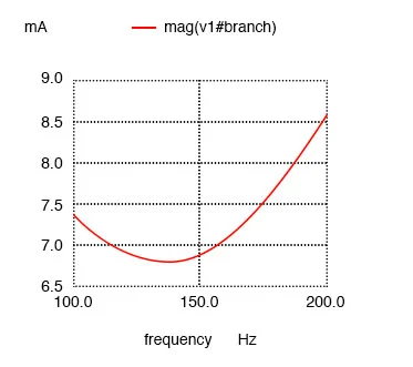
 Parallel LC with resistance in serieis with C.
Here, an extra resistor (Rbogus) is necessary to prevent SPICE from
encountering trouble in analysis. SPICE can’t handle an inductor connected
directly in parallel with any voltage source or any other inductor, so the
addition of a series resistor is necessary to “break up” the voltage
source/inductor loop that would otherwise be formed.
This resistor is chosen to be a very low value for minimum impact on the
circuit’s behavior.
resonant circuit
v1 1 0 ac 1 sin
r1 1 2 100
c1 2 0 10u
rbogus 1 3 1e-12
l1 3 0 100m
.ac lin 20 100 400
.plot ac i(v1)
.end
Minimum current at roughly 180 Hz instead of 159.2 Hz!
Results:
Parallel LC with resistance in serieis with C.
Parallel LC with resistance in serieis with C.
Here, an extra resistor (Rbogus) is necessary to prevent SPICE from
encountering trouble in analysis. SPICE can’t handle an inductor connected
directly in parallel with any voltage source or any other inductor, so the
addition of a series resistor is necessary to “break up” the voltage
source/inductor loop that would otherwise be formed.
This resistor is chosen to be a very low value for minimum impact on the
circuit’s behavior.
resonant circuit
v1 1 0 ac 1 sin
r1 1 2 100
c1 2 0 10u
rbogus 1 3 1e-12
l1 3 0 100m
.ac lin 20 100 400
.plot ac i(v1)
.end
Minimum current at roughly 180 Hz instead of 159.2 Hz!
Results:
 Resistance in series with C shifts minimum current from calculated 159.2 Hz
to roughly 180 Hz.
Resistance in series with C shifts minimum current from calculated 159.2 Hz
to roughly 180 Hz.
Series LC Circuits
Switching our attention to series LC circuits, we experiment with placing
significant resistances in parallel with either L or C. In the following
series circuit examples, a 1 Ω resistor (R1) is placed in series with the
inductor and capacitor to limit total current at resonance.
The “extra” resistance inserted to influence resonant frequency effects
is the 100 Ω resistor, R2. The results are shown in the figure below.
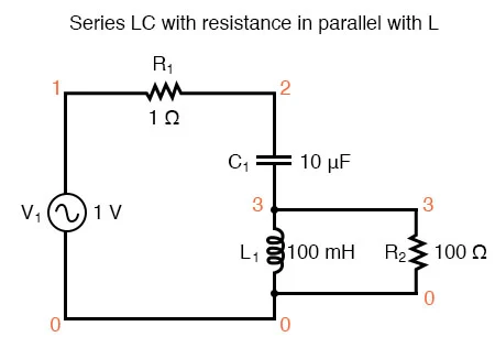 Series LC resonant circuit with resistance in parallel with L.
resonant circuit
v1 1 0 ac 1 sin
r1 1 2 1
c1 2 3 10u
l1 3 0 100m
r2 3 0 100
.ac lin 20 100 400
.plot ac i(v1)
.end
Maximum current at roughly 178.9 Hz instead of 159.2 Hz!
Results:
Series LC resonant circuit with resistance in parallel with L.
resonant circuit
v1 1 0 ac 1 sin
r1 1 2 1
c1 2 3 10u
l1 3 0 100m
r2 3 0 100
.ac lin 20 100 400
.plot ac i(v1)
.end
Maximum current at roughly 178.9 Hz instead of 159.2 Hz!
Results:
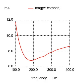
 Series resonant circuit with resistance in parallel with L shifts maximum
current from 159.2 Hz to roughly 180 Hz.
And finally, a series LC circuit with the significant resistance in parallel
with the capacitor The shifted resonance is shown below.
Series resonant circuit with resistance in parallel with L shifts maximum
current from 159.2 Hz to roughly 180 Hz.
And finally, a series LC circuit with the significant resistance in parallel
with the capacitor The shifted resonance is shown below.
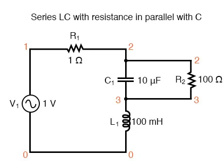 Series LC resonant circuit with resistance in parallel with C.
resonant circuit
v1 1 0 ac 1 sin
r1 1 2 1
c1 2 3 10u
r2 2 3 100
l1 3 0 100m
.ac lin 20 100 200
.plot ac i(v1)
.end
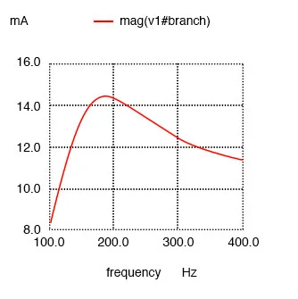
Maximum current at 136.8 Hz instead of 159.2 Hz!
Results:
Series LC resonant circuit with resistance in parallel with C.
resonant circuit
v1 1 0 ac 1 sin
r1 1 2 1
c1 2 3 10u
r2 2 3 100
l1 3 0 100m
.ac lin 20 100 200
.plot ac i(v1)
.end
Maximum current at 136.8 Hz instead of 159.2 Hz!
Results:
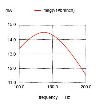 Resistance in parallel with C in series resonant circuit shifts current
maximum from calculated 159.2 Hz to about 136.8 Hz.
Resistance in parallel with C in series resonant circuit shifts current
maximum from calculated 159.2 Hz to about 136.8 Hz.
Antiresonance in LC Circuits
The tendency for added resistance to skew the point at which impedance
reaches a maximum or minimum in an LC circuit is called antiresonance. The
astute observer will notice a pattern between the four SPICE examples given
above, in terms of how resistance affects the resonant peak of a circuit:
Parallel (“tank”) LC circuit:
- R in series with L: resonant frequency shifted down
- R in series with C: resonant frequency shifted up
Series LC circuit:
- R in parallel with L: resonant frequency shifted up
- R in parallel with C: resonant frequency shifted down
Again, this illustrates the complementary nature of capacitors and
inductors: how resistance in series with one creates an antiresonance effect
equivalent to resistance in parallel with the other. If you look even closer
to the four SPICE examples given, you’ll see that the frequencies are
shifted by the same amount, and that the shape of the complementary graphs
are mirror-images of each other!
Antiresonance
Antiresonance is an effect that resonant circuit designers must be aware of.
The equations for determining antiresonance “shift” are complex, and
will not be covered in this brief lesson. It should suffice the beginning
student of electronics to understand that the effect exists, and what its
general tendencies are.
The Skin Effect
Added resistance in an LC circuit is no academic matter. While it is
possible to manufacture capacitors with negligible unwanted resistances,
inductors are typically plagued with substantial amounts of resistance due
to the long lengths of wire used in their construction.
What is more, the resistance of wire tends to increase as frequency goes up,
due to a strange phenomenon known as the skin effect where AC current tends
to be excluded from travel through the very center of a wire, thereby
reducing the wire’s effective cross-sectional area.
Thus, inductors not only have resistance, but changing, frequency-dependent
resistance at that.
Added Resistance in Circuits
As if the resistance of an inductor’s wire weren’t enough to cause
problems, we also have to contend with the “core losses” of iron-core
inductors, which manifest themselves as added resistance in the circuit.
Since iron is a conductor of electricity as well as a conductor of magnetic
flux, changing flux produced by alternating current through the coil will
tend to induce electric currents in the core itself (eddy currents).
This effect can be thought of as though the iron core of the transformer
were a sort of secondary transformer coil powering a resistive load: the
less-than-perfect conductivity of the iron metal. This effects can be
minimized with laminated cores, good core design high-grade materials, but
RLC Circuits
One notable exception to the rule of circuit resistance causing a resonant
frequency shift is the case of series resistor-inductor-capacitor
(“RLC”) circuits. So long as all components are connected in series with
each other, the resonant frequency of the circuit will be unaffected by the
resistance. The resulting plot is shown below.
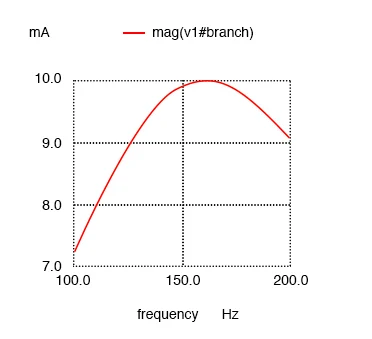
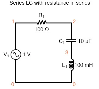 Series LC with resistance in series.
series rlc circuit
v1 1 0 ac 1 sin
r1 1 2 100
c1 2 3 10u
l1 3 0 100m
.ac lin 20 100 200
.plot ac i(v1)
.end
Maximum current at 159.2 Hz once again!
Results:
Series LC with resistance in series.
series rlc circuit
v1 1 0 ac 1 sin
r1 1 2 100
c1 2 3 10u
l1 3 0 100m
.ac lin 20 100 200
.plot ac i(v1)
.end
Maximum current at 159.2 Hz once again!
Results:
 Resistance in series resonant circuit leaves current maximum at calculated
159.2 Hz, broadening the curve.
Note that the peak of the current graph has not changed from the earlier
series LC circuit (the one with the 1 Ω token resistance in it), even
though the resistance is now 100 times greater. The only thing that has
changed is the “sharpness” of the curve.
Obviously, this circuit does not resonate as strongly as one with less
series resistance (it is said to be “less selective”), but at least it
has the same natural frequency!
Resistance in series resonant circuit leaves current maximum at calculated
159.2 Hz, broadening the curve.
Note that the peak of the current graph has not changed from the earlier
series LC circuit (the one with the 1 Ω token resistance in it), even
though the resistance is now 100 times greater. The only thing that has
changed is the “sharpness” of the curve.
Obviously, this circuit does not resonate as strongly as one with less
series resistance (it is said to be “less selective”), but at least it
has the same natural frequency!
Antiresonance’s Dampening Effect
It is noteworthy that antiresonance has the effect of dampening the
oscillations of free-running LC circuits such as tank circuits. In the
beginning of this chapter we saw how a capacitor and inductor connected
directly together would act something like a pendulum, exchanging voltage
and current peaks just like a pendulum exchanges kinetic and potential
energy.
In a perfect tank circuit (no resistance), this oscillation would continue
forever, just as a frictionless pendulum would continue to swing at its
resonant frequency forever. But frictionless machines are difficult to find
in the real world, and so are lossless tank circuits.
Energy lost through resistance (or inductor core losses or radiated
electromagnetic waves or . . .) in a tank circuit will cause the
oscillations to decay in amplitude until they are no more. If enough energy
losses are present in a tank circuit, it will fail to resonate at all.
Antiresonance’s dampening effect is more than just a curiosity: it can be
used quite effectively to eliminate unwanted oscillations in circuits
containing stray inductances and/or capacitances, as almost all circuits do.
Take note of the following L/R time delay circuit: (Figure below)
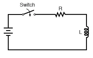 L/R time delay circuit
The idea of this circuit is simple: to “charge” the inductor when the
switch is closed. The rate of inductor charging will be set by the ratio
L/R, which is the time constant of the circuit in seconds.
However, if you were to build such a circuit, you might find unexpected
oscillations (AC) of voltage across the inductor when the switch is closed.
(Figure below) Why is this? There’s no capacitor in the circuit, so how
can we have resonant oscillation with just an inductor, resistor, and
battery?
L/R time delay circuit
The idea of this circuit is simple: to “charge” the inductor when the
switch is closed. The rate of inductor charging will be set by the ratio
L/R, which is the time constant of the circuit in seconds.
However, if you were to build such a circuit, you might find unexpected
oscillations (AC) of voltage across the inductor when the switch is closed.
(Figure below) Why is this? There’s no capacitor in the circuit, so how
can we have resonant oscillation with just an inductor, resistor, and
battery?
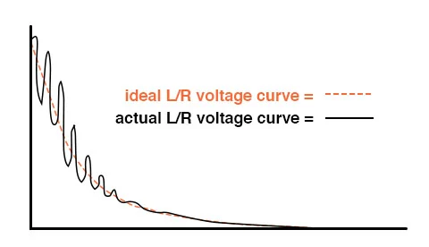 Inductor ringing due to resonance with stray capacitance.
All inductors contain a certain amount of stray capacitance due to turn-to
-turn and turn-to-core insulation gaps. Also, the placement of circuit
conductors may create stray capacitance. While clean circuit layout is
important in eliminating much of this stray capacitance, there will always
be some that you cannot eliminate.
If this causes resonant problems (unwanted AC oscillations), added
resistance may be a way to combat it. If resistor R is large enough, it will
cause a condition of antiresonance, dissipating enough energy to prohibit
the inductance and stray capacitance from sustaining oscillations for very
long.
Interestingly enough, the principle of employing resistance to eliminate
unwanted resonance is one frequently used in the design of mechanical
systems, where any moving object with mass is a potential resonator.
A very common application of this is the use of shock absorbers in
automobiles. Without shock absorbers, cars would bounce wildly at their
resonant frequency after hitting any bump in the road. The shock
absorber’s job is to introduce a strong antiresonant effect by dissipating
energy hydraulically (in the same way that a resistor dissipates energy
electrically).
Inductor ringing due to resonance with stray capacitance.
All inductors contain a certain amount of stray capacitance due to turn-to
-turn and turn-to-core insulation gaps. Also, the placement of circuit
conductors may create stray capacitance. While clean circuit layout is
important in eliminating much of this stray capacitance, there will always
be some that you cannot eliminate.
If this causes resonant problems (unwanted AC oscillations), added
resistance may be a way to combat it. If resistor R is large enough, it will
cause a condition of antiresonance, dissipating enough energy to prohibit
the inductance and stray capacitance from sustaining oscillations for very
long.
Interestingly enough, the principle of employing resistance to eliminate
unwanted resonance is one frequently used in the design of mechanical
systems, where any moving object with mass is a potential resonator.
A very common application of this is the use of shock absorbers in
automobiles. Without shock absorbers, cars would bounce wildly at their
resonant frequency after hitting any bump in the road. The shock
absorber’s job is to introduce a strong antiresonant effect by dissipating
energy hydraulically (in the same way that a resistor dissipates energy
electrically).
REVIEW:
- Added resistance to an LC circuit can cause a condition known as
antiresonance, where the peak impedance effects happen at frequencies other
than that which gives equal capacitive and inductive reactances.
- Resistance inherent in real-world inductors can contribute greatly to
conditions of antiresonance. One source of such resistance is the skin
effect, caused by the exclusion of AC current from the center of conductors.
Another source is that of core losses in iron-core inductors.
- In a simple series LC circuit containing resistance (an “RLC”
circuit), resistance does not produce antiresonance. Resonance still occurs
when capacitive and inductive reactances are equal.