Resistance This is essentially friction against the flow of current. It is present in all conductors to some extent (except superconductors!), most notably in resistors. When the alternating current goes through a resistance, a voltage drop is produced that is in-phase with the current. Resistance is mathematically symbolized by the letter “R” and is measured in the unit of ohms (Ω).
Reactance This is essentially inertia against the flow of current. It is present anywhere electric or magnetic fields are developed in proportion to an applied voltage or current, respectively; but most notably in capacitors and inductors. When the alternating current goes through a pure reactance, a voltage drop is produced that is 90° out of phase with the current. Reactance is mathematically symbolized by the letter “X” and is measured in the unit of ohms (Ω).
Impedance This is a comprehensive expression of any and all forms of opposition to current flow, including both resistance and reactance. It is present in all circuits, and in all components. When the alternating current goes through an impedance, a voltage drop is produced that is somewhere between 0° and 90° out of phase with the current. Impedance is mathematically symbolized by the letter “Z” and is measured in the unit of ohms (Ω), in complex form. Perfect resistors possess resistance, but not reactance. Perfect inductors and perfect capacitors possess reactance but no resistance. All components possess impedance, and because of this universal quality, it makes sense to translate all component values (resistance, inductance, capacitance) into common terms of impedance as the first step in analyzing an AC circuit.
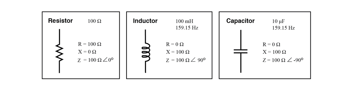 Perfect resistor, inductor, and capacitor.
The impedance phase angle for any component is the phase shift between the
voltage across that component and current through that component.
For a perfect resistor, the voltage drop and current are always in phase
with each other, and so the impedance angle of a resistor is said to be 0°.
For a perfect inductor, voltage drop always leads current by 90°, and so an
inductor’s impedance phase angle is said to be +90°.
For a perfect capacitor, voltage drop always lags current by 90°, and so a
capacitor’s impedance phase angle is said to be -90°.
Impedances in AC behave analogously to resistances in DC circuits: they add
in series, and they diminish in parallel. A revised version of Ohm’s Law,
based on impedance rather than resistance, looks like this:
Perfect resistor, inductor, and capacitor.
The impedance phase angle for any component is the phase shift between the
voltage across that component and current through that component.
For a perfect resistor, the voltage drop and current are always in phase
with each other, and so the impedance angle of a resistor is said to be 0°.
For a perfect inductor, voltage drop always leads current by 90°, and so an
inductor’s impedance phase angle is said to be +90°.
For a perfect capacitor, voltage drop always lags current by 90°, and so a
capacitor’s impedance phase angle is said to be -90°.
Impedances in AC behave analogously to resistances in DC circuits: they add
in series, and they diminish in parallel. A revised version of Ohm’s Law,
based on impedance rather than resistance, looks like this:
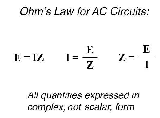 ohms law for ac circuits
RELATED WORKSHEETS:
Impedance Worksheet
AC Power Worksheet
Capacitive Reactance Worksheet
Inductive Reactance Worksheet
ohms law for ac circuits
RELATED WORKSHEETS:
Impedance Worksheet
AC Power Worksheet
Capacitive Reactance Worksheet
Inductive Reactance Worksheet