Decode and Send 433Mhz RF signals
From: https://randomnerdtutorials.com/decode-and-send-433-mhz-rf-signals-with-arduino/
Decode and Send 433 MHz RF Signals with Arduino
This guide shows how to use an Arduino to decode 433 MHz signals from RF
remotes, and send them with an Arduino and a 433 MHz transmitter to remotely
control mains switches outlets.


Why Decoding RF Signals?
I’ve tried different methods of controlling the mains voltage, but some of
the methods require:
- Experience dealing with AC voltage
- Opening holes in your wall/ceiling/switches
- Modifying the electrical panel
- Knowing the electrical rules for each country
It’s difficult to come up with a solution that is safe and works for
everyone. One of the easiest and safest ways to remotely control appliances
connected to mains voltage is using radio frequency (RF) controlled outlets.
Why? Using remote controlled outlets have 5 benefits:
- Fairly inexpensive
- Easy to get
- Works with ESP8266 and Arduino
- Safe to use
- Works in any country
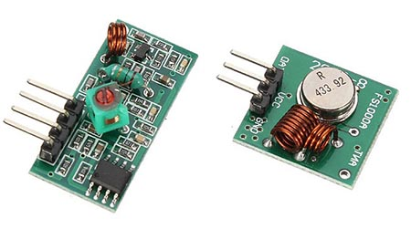
Parts Required
For this tutorial, you need the following parts:
Note: you need to buy remote controlled outlets that operate at a RF of
433MHz. They should say the operating RF either in the product page or in
the label.
You can use the preceding links or go directly to MakerAdvisor.com/tools to
find all the parts for your projects at the best price!
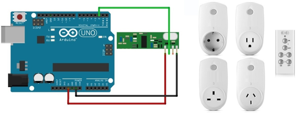
Example
Here’s how they look:
Setting the RF Channels
I’ve set my remote control to the I position.
 The outlets must be both on the I position. I’ve selected channels 3 and 4
for the outlets (you can use any channel you want).
The outlets must be both on the I position. I’ve selected channels 3 and 4
for the outlets (you can use any channel you want).
 If you plug them to an outlet, you should be able to control the remote
controlled outlets with your remote control.
If you plug them to an outlet, you should be able to control the remote
controlled outlets with your remote control.
Installing the RC Switch Library
The RC Switch library provides an easy way of using your ESP8266, ESP32, or
Arduino to operate remote radio controlled devices. This will most likely
work with all popular low-cost power outlet sockets.
- Click here to download the RC Switch library. You should have a .zip
folder in your Downloads folder
- Unzip the .zip folder and you should get rc-switch-master folder
- Rename your folder from rc-switch-master to rc_switch
- Move the rc_switch folder to your Arduino IDE installation libraries
folder
- Then, re-open your Arduino IDE
Opening the Decoder Sketch
You need to decode the signals that your remote control sends, so that the
Arduino or ESP8266 can reproduce those signals and ultimately control the
outlets.
The library comes with several sketch examples. Within the Arduino IDE
software, you need to go to:
File > Examples > RC_Switch > ReceiveDemo_Advanced. This next sketch
opens:
/*H*******************************************************
* Example for receiving
https://github.com/sui77/rc-switch/
If you want to visualize a telegram copy the raw data and paste it into
http://test.sui.li/oszi/
*********************************************************/
#include <RCSwitch.h>
// **************** DEFINES ****************************
// **************** PROTOTYPES *************************
// **************** VARIABLES **************************
RCSwitch mySwitch = RCSwitch();
/*F*******************************************************
*
*********************************************************/
void
setup()
{
Serial.begin( 9600 );
mySwitch.enableReceive( 0 ); // Receiver on interrupt 0 => that is pin #2
}
/*F*******************************************************
*
*********************************************************/
void
loop()
{
if( mySwitch.available())
{
output( mySwitch.getReceivedValue(), mySwitch.getReceivedBitlength()
, mySwitch.getReceivedDelay(), mySwitch.getReceivedRawdata()
, mySwitch.getReceivedProtocol());
mySwitch.resetAvailable();
}
}
You must open the example using:
File > Examples > RC_Switch > ReceiveDemo_Advanced, so it automatically
also loads the output file.
 Having an Arduino board connected to your computer follow these
instructions:
Having an Arduino board connected to your computer follow these
instructions:
- Go to the Tools tab
- Select Arduino UNO board
- Select the COM port
- Press the Upload button.
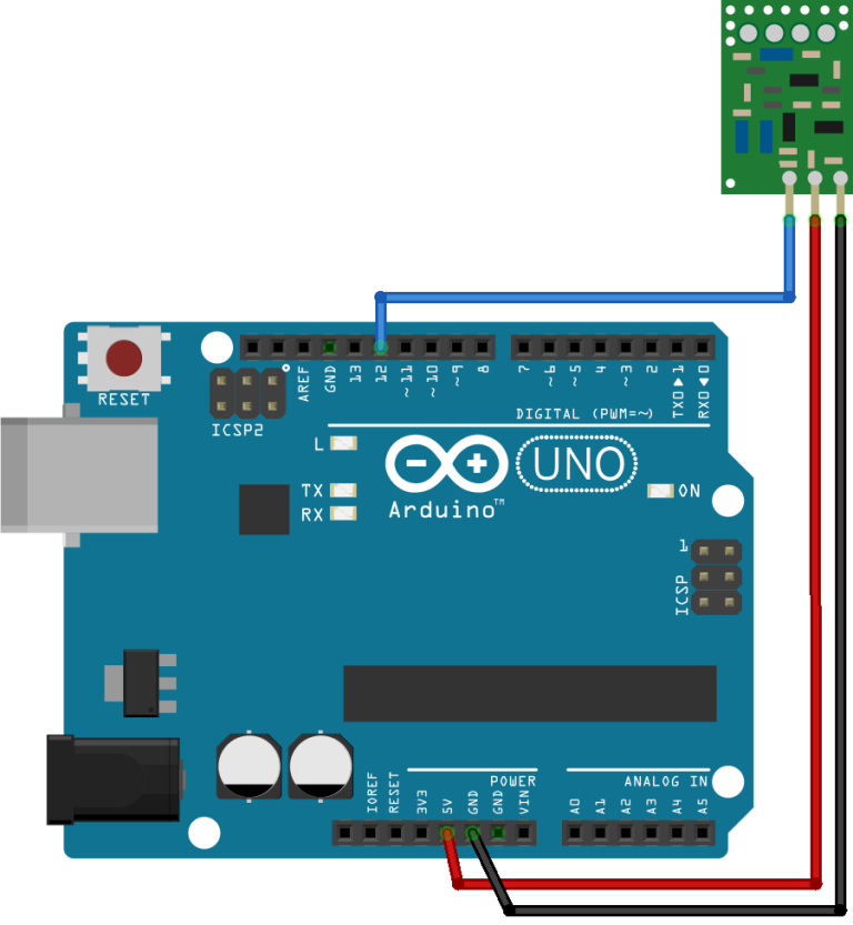
Decoder – Schematics
After uploading the sketch, connect an 433MHz RF receiver to Digital Pin 2
of your Arduino UNO board:
Decode RF Signals (codes)
Open the Arduino IDE serial monitor and start pressing the buttons. As shown
in the video demonstration below:
After pressing each button one time, you can see the binary code for each
button (it’s highlighted in red):
 Save your binary codes for each button press (you can also use the Decimal
or Tri-State codes):
Save your binary codes for each button press (you can also use the Decimal
or Tri-State codes):
- Button 3 ON = (24Bit) Binary: 000101010101000101010101
- Button 3 OFF = (24Bit) Binary: 000101010101000101010100
- Button 4 ON = (24Bit) Binary: 000101010101010001010101
- Button 4 OFF = (24Bit) Binary: 000101010101010001010100
Save your Pulse Length: 416 Microseconds and Protocol: 1.
Send the RF Signals (codes)
You’ll need to customize the next sketch with your binary codes, pulse
length and protocol:
/*H*******************************************************
* Based on the SendDemo example from the RC Switch library
https://github.com/sui77/rc-switch/
*********************************************************/
#include <RCSwitch.h>
// **************** DEFINES ****************************
// **************** PROTOTYPES *************************
// **************** VARIABLES **************************
RCSwitch mySwitch = RCSwitch();
/*F*******************************************************
*
*********************************************************/
void
setup()
{
Serial.begin( 9600 );
// Transmitter is connected to Arduino Pin #10
mySwitch.enableTransmit( 10 );
// Optional set pulse length.
mySwitch.setPulseLength( REPLACE_WITH_YOUR_PULSE_LENGTH );
// Optional set protocol (default is 1, will work for most outlets)
mySwitch.setProtocol( REPLACE_WITH_YOUR_PROTOCOL );
// Optional set number of transmission repetitions.
// mySwitch.setRepeatTransmit( 15 );
}
/*F*******************************************************
*
*********************************************************/
void
loop()
{
// Binary code - button 3
mySwitch.send( "000101010101000101010101" );
delay( 1000 );
mySwitch.send( "000101010101000101010100" );
delay( 1000 );
// Binary code - button 4
mySwitch.send( "000101010101010001010101" );
delay( 1000 );
mySwitch.send( "000101010101010001010100" );
delay( 1000 );
}
In my case, the pulse length and protocol looks like this:
// Optional set pulse length.
mySwitch.setPulseLength( 416 );
// Optional set protocol (default is 1, will work for most outlets)
mySwitch.setProtocol( 1 );
Here’s a binary sender example (you have to replace with your own binary
codes):
mySwitch.send( "000101010101000101010101" );
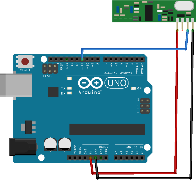
Sender Schematics
After uploading the sketch to your Arduino board, assemble this circuit:
Both of your outlets should be turning on and off continuously.
Wrapping Up
I hope you’ve found this guide useful. If you like this post probably you
might like my next ones, so make sure you subscribe the RNT blog.
You can use the concepts learned in this tutorial with your ESP8266 or
ESP32.