 I got the idea for this circuit from one of my professors. That design
wasn't meant for passing frequencies high enough to be able to pass an audio
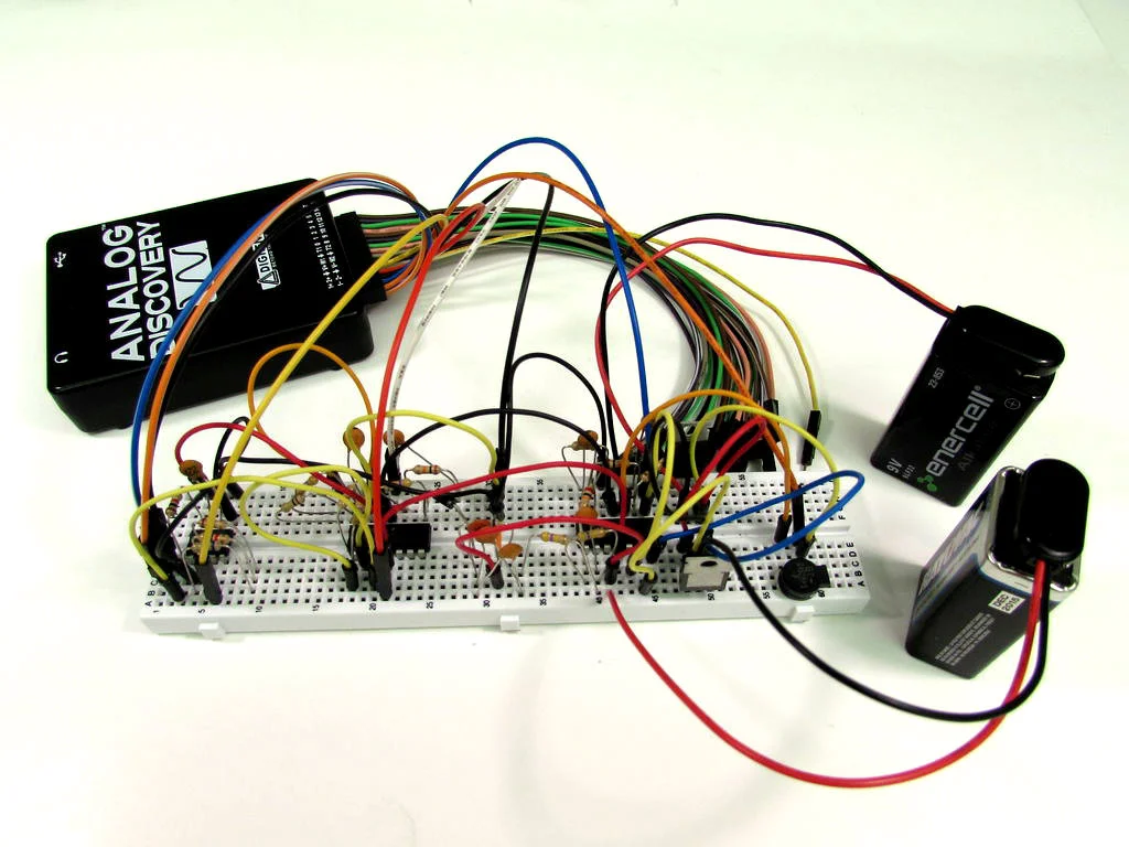
file, e.g. 500Hz+, so I built this by modifying the carrier and signal
frequencies, using only the Digilent Analog Discovery and the Analog Parts
Kit. It should be noted that this circuit is primarily for educational
purposes. Also note that there is no radio transmission here either. FM
doesn't necessarily mean radio waves have to be involved.
Throughout this Instructable I will be going through some of the functions
and features of the Analog Discovery, but it will not be an exhaustive
tutorial.
I got the idea for this circuit from one of my professors. That design
wasn't meant for passing frequencies high enough to be able to pass an audio
file, e.g. 500Hz+, so I built this by modifying the carrier and signal
frequencies, using only the Digilent Analog Discovery and the Analog Parts
Kit. It should be noted that this circuit is primarily for educational
purposes. Also note that there is no radio transmission here either. FM
doesn't necessarily mean radio waves have to be involved.
Throughout this Instructable I will be going through some of the functions
and features of the Analog Discovery, but it will not be an exhaustive
tutorial.
Step 1: Parts and Tools
 Parts and Tools
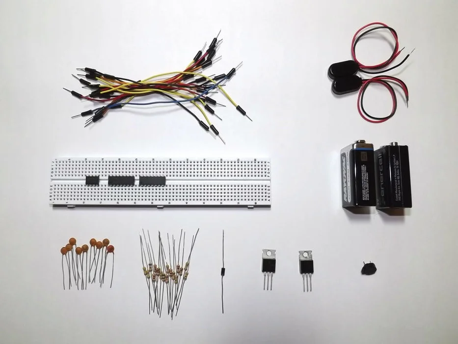
All of the parts listed below are provided in the Analog Starter Kit, except
for the 9V batteries and clips. They should also be available through
various online suppliers, local shops, or the salvage bin on your
workbench.
The Parts:
2 - OP482 quad op-amps (datasheet)
- AD654 voltage to frequency converter (datasheet)
9 - ceramic capacitors:
2 - 39pF (39)
2 - 100pF (101)
2 - 1nF (102)
2 - 4.7nF (472)
1 - 10nF (103)
- 17 carbon film resistors:
1 - 68
3 - 1k
1 - 6.8k
3 - 10k
1 - 20k
1 - 47k
2 - 100k
5 - 470k
1 - 1N4001 rectifier diode
1 - speaker
- solderless breadboard
- jumper wires
(optional)
1 - TIP31C NPN BJT
1 - TIP32C PNP BJT
2 - 9V batteries with clips
The Tools:
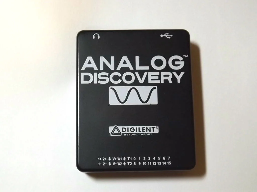
- Digilent Analog Discovery
- Waveforms software (free but required to run the Analog Discovery)
- short, free .wav file download.
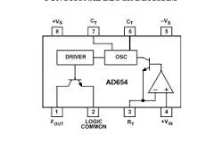
Pin-out diagrams are included for the OP482 quad op-amp and AD654 voltage to
frequency converter, also called a voltage controlled oscillator or VCO.
Parts and Tools
All of the parts listed below are provided in the Analog Starter Kit, except
for the 9V batteries and clips. They should also be available through
various online suppliers, local shops, or the salvage bin on your
workbench.
The Parts:
2 - OP482 quad op-amps (datasheet)
- AD654 voltage to frequency converter (datasheet)
9 - ceramic capacitors:
2 - 39pF (39)
2 - 100pF (101)
2 - 1nF (102)
2 - 4.7nF (472)
1 - 10nF (103)
- 17 carbon film resistors:
1 - 68
3 - 1k
1 - 6.8k
3 - 10k
1 - 20k
1 - 47k
2 - 100k
5 - 470k
1 - 1N4001 rectifier diode
1 - speaker
- solderless breadboard
- jumper wires
(optional)
1 - TIP31C NPN BJT
1 - TIP32C PNP BJT
2 - 9V batteries with clips
The Tools:
- Digilent Analog Discovery
- Waveforms software (free but required to run the Analog Discovery)
- short, free .wav file download.
Pin-out diagrams are included for the OP482 quad op-amp and AD654 voltage to
frequency converter, also called a voltage controlled oscillator or VCO.
Step 2: Designing
 Designing
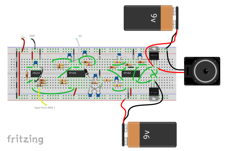
The schematic for this can be daunting to say the least. When I first
started working with it, I got lost all the time and had to keep going back
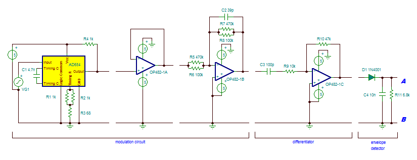
over it again and again. You'll notice in the schematic that there are
breaks throughout the design. Each of those breaks represents a good
stopping point for verifying the circuit function. Take it slow and add one
section at a time. The OP482 ICs are quad op-amps, meaning four op-amps on
one piece of silicone. That can make it tricky to hook everything together
as components can get crowded. This project can be built using individual op
-amps if that is easier for you, but I would recommend using the OP27 and
not the LM741. The LM741 should work, but I have had problems with it when
it comes to needing fast, reliable response times. The specs are just a bit
too slow for some applications, specifically the skew rate when you need
high gain at a relatively high frequency.
For clarification the schematic image is broken up. Point A matches to point
A, B with B.
Designing
The schematic for this can be daunting to say the least. When I first
started working with it, I got lost all the time and had to keep going back
over it again and again. You'll notice in the schematic that there are
breaks throughout the design. Each of those breaks represents a good
stopping point for verifying the circuit function. Take it slow and add one
section at a time. The OP482 ICs are quad op-amps, meaning four op-amps on
one piece of silicone. That can make it tricky to hook everything together
as components can get crowded. This project can be built using individual op
-amps if that is easier for you, but I would recommend using the OP27 and
not the LM741. The LM741 should work, but I have had problems with it when
it comes to needing fast, reliable response times. The specs are just a bit
too slow for some applications, specifically the skew rate when you need
high gain at a relatively high frequency.
For clarification the schematic image is broken up. Point A matches to point
A, B with B.
Step 3: Frequency Modulation
 Frequency Modulation
I won't go into the details of FM or AM technology too much here. I would
refer you to Wikipedia for that (note the animation on the right side of the
page). In a nutshell, for FM signals, the frequency of the signal varies
based on the voltage level coming in. So a high voltage gives a high
frequency, and vice versa. With AM, the frequency stays the same, but the
amplitude goes high or low depending on the input voltage. As you will see,
this circuit actually uses both.
The higher frequency signal is the carrier frequency, while the original
signal is the data that you want to relay. We will use the data signal to
modulate a much higher frequency carrier wave. Later we will filter out the
carrier and recover the data.
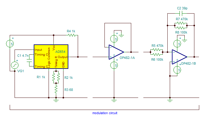
The first three sections of the schematic are the modulation circuit. We
first modulate the carrier wave, then amplify it. The AD654 changes the
frequency of the output based on the voltage level of the input. The timing
resistors and capacitors give a base frequency value for the IC to work with
based on the equation found in the datasheet.
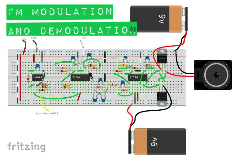
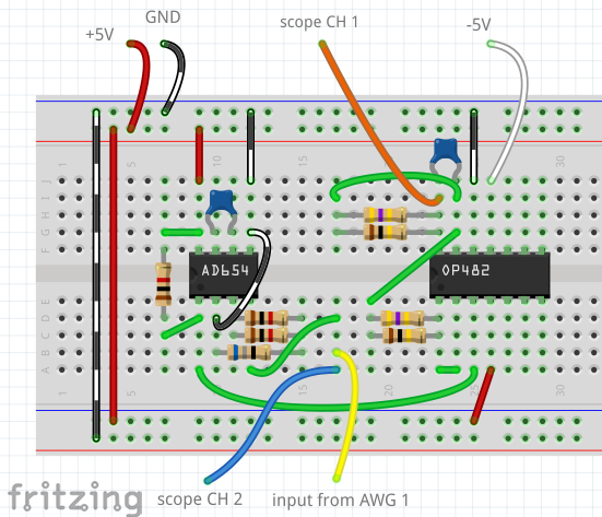
Using pages 1 and 4 of the datasheet for the AD654, connect the components
as shown. Note that 'Vs' indicates voltage supply, so '+Vs' is +5V and '-Vs'
is ground. '+Vin' is the signal coming from the Analog Discovery AWG Channel
1 pin, labeled 'input' in the schematic.
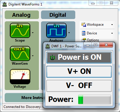
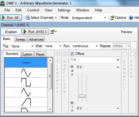
Turn on the Voltage function from the Waveforms main window (image 2). Click
V+ to 'ON', connect the red V+ wire from the Discovery header to pin 8 on
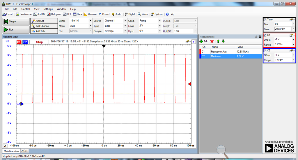
the AD654, then turn it on. Using the Discovery's AWG channel 1, output a
1VDC signal (image 3) and plug it into pin 4 of the AD654. You should get a
readout on the scope like image 4.
Next we add the first OP482. The first part is a simple voltage follower or
buffer. Since op-amps are active components, we will get a boost in current
from this part. Next we add an active low-pass filter set to cutoff at
approximately 50kHz, which is high enough to allow our signal to pass
through but low enough to filter out random high frequency noise we don't
want. When connecting the OP482, connect the Discovery's red V+ wire to pin
4 and the white V- wire to pin 11. Turn on the power supply (like in image
2, but both channels this time) before turning on AWG 1 with the signal. Set
AWG 1 to an amplitude of 500mV this time. Your scope should look something
image 5.
Frequency Modulation
I won't go into the details of FM or AM technology too much here. I would
refer you to Wikipedia for that (note the animation on the right side of the
page). In a nutshell, for FM signals, the frequency of the signal varies
based on the voltage level coming in. So a high voltage gives a high
frequency, and vice versa. With AM, the frequency stays the same, but the
amplitude goes high or low depending on the input voltage. As you will see,
this circuit actually uses both.
The higher frequency signal is the carrier frequency, while the original
signal is the data that you want to relay. We will use the data signal to
modulate a much higher frequency carrier wave. Later we will filter out the
carrier and recover the data.
The first three sections of the schematic are the modulation circuit. We
first modulate the carrier wave, then amplify it. The AD654 changes the
frequency of the output based on the voltage level of the input. The timing
resistors and capacitors give a base frequency value for the IC to work with
based on the equation found in the datasheet.
Using pages 1 and 4 of the datasheet for the AD654, connect the components
as shown. Note that 'Vs' indicates voltage supply, so '+Vs' is +5V and '-Vs'
is ground. '+Vin' is the signal coming from the Analog Discovery AWG Channel
1 pin, labeled 'input' in the schematic.
Turn on the Voltage function from the Waveforms main window (image 2). Click
V+ to 'ON', connect the red V+ wire from the Discovery header to pin 8 on
the AD654, then turn it on. Using the Discovery's AWG channel 1, output a
1VDC signal (image 3) and plug it into pin 4 of the AD654. You should get a
readout on the scope like image 4.
Next we add the first OP482. The first part is a simple voltage follower or
buffer. Since op-amps are active components, we will get a boost in current
from this part. Next we add an active low-pass filter set to cutoff at
approximately 50kHz, which is high enough to allow our signal to pass
through but low enough to filter out random high frequency noise we don't
want. When connecting the OP482, connect the Discovery's red V+ wire to pin
4 and the white V- wire to pin 11. Turn on the power supply (like in image
2, but both channels this time) before turning on AWG 1 with the signal. Set
AWG 1 to an amplitude of 500mV this time. Your scope should look something
image 5.
Step 4: Differentiator and Envelope Detector
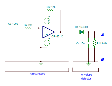
 Differentiator and Envelope Detector
The theory behind most of these parts is a bit much to get into here. Again,
check out wikipedia for the differentiator (note that this one is active
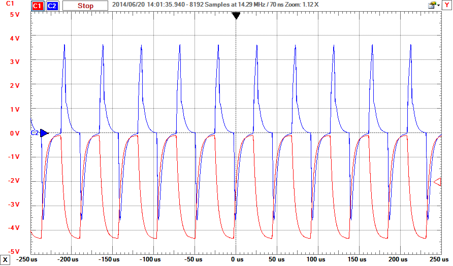
because of the op-amp) and the envelope detector explanations. In short, the
differentiator, believe it or not, differentiates the signal (think calculus
and it makes total sense). As the input signal rises or falls quickly (high
frequency), the output amplitude increases. As the input rises or falls
slowly (low frequency), the output amplitude decreases closer to 0. This has
the interesting effect of turning the FM signal into an AM signal. See the o
-scope display in image 2 for a comparison (scope CH 1 to pin 14 of the
OP482 and CH 2 to pin 8).
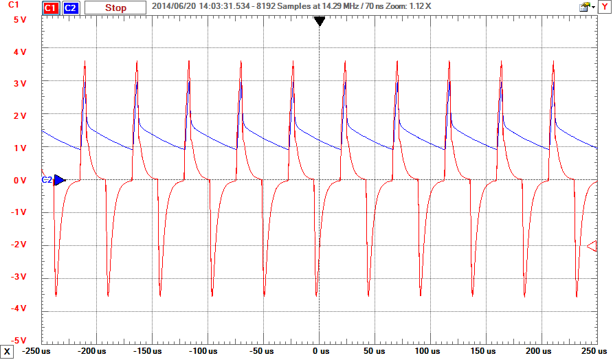
The envelope detector detects only the top edge of the signal, so as the
amplitude rises and falls, so will the signal coming out of the envelope
detector. See image 3 for an example (CH 1 to pin 8 of OP482 and CH 2 to
cathode of 1N4001 diode).
Differentiator and Envelope Detector
The theory behind most of these parts is a bit much to get into here. Again,
check out wikipedia for the differentiator (note that this one is active
because of the op-amp) and the envelope detector explanations. In short, the
differentiator, believe it or not, differentiates the signal (think calculus
and it makes total sense). As the input signal rises or falls quickly (high
frequency), the output amplitude increases. As the input rises or falls
slowly (low frequency), the output amplitude decreases closer to 0. This has
the interesting effect of turning the FM signal into an AM signal. See the o
-scope display in image 2 for a comparison (scope CH 1 to pin 14 of the
OP482 and CH 2 to pin 8).
The envelope detector detects only the top edge of the signal, so as the
amplitude rises and falls, so will the signal coming out of the envelope
detector. See image 3 for an example (CH 1 to pin 8 of OP482 and CH 2 to
cathode of 1N4001 diode).
Step 5: Filtering
 Filtering
The signal from the envelope detector doesn't have much amplitude and
contains quite a bit of noise. So we add several filters to both clarify and
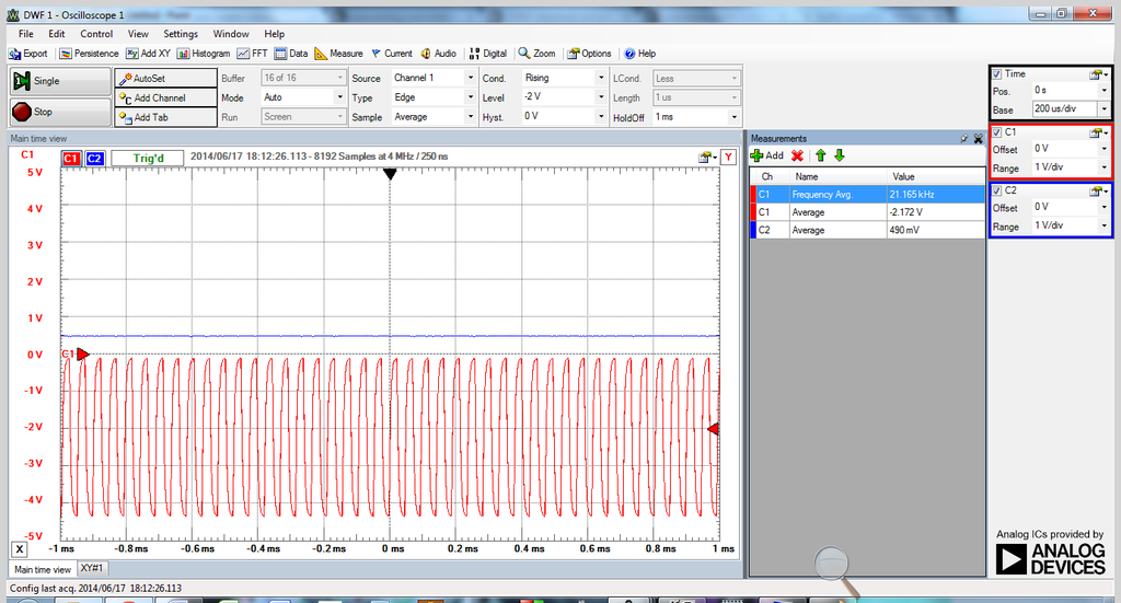
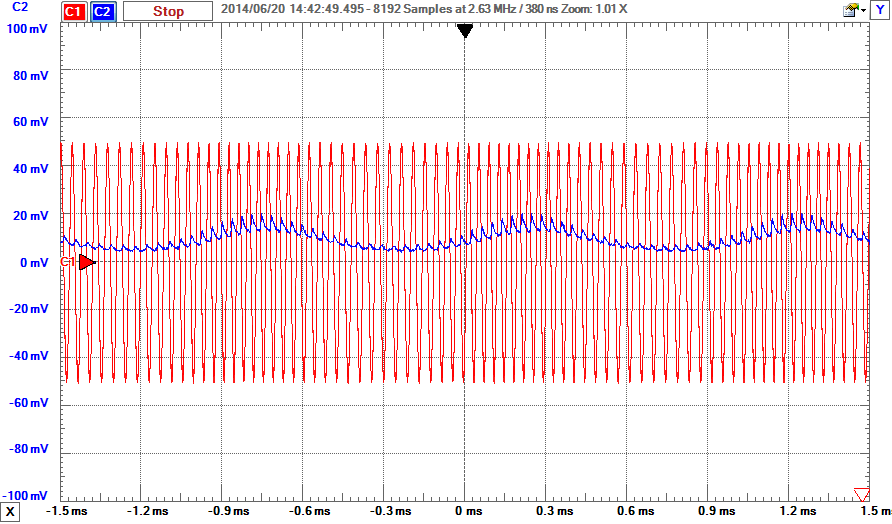
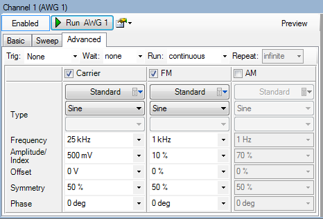
boost the signal. Look at the o-scope display in image 2. The red CH 1
signal is a 25kHz carrier with a 1kHz modulation frequency, amplitude of
500mV and index of 10%. These settings are all under the advanced tab on the
Analog Discovery AWG tool (see image 3) if you would like to generate the
signal yourself. This signal then is inserted into the input of the
differentiator, bypassing the modulation circuit for now. The blue CH 2 is
the output of the envelope detector, before any filtering. Do you see the
scale on the left of the display in image 2? Each division is 20mV for CH 2.
Most scopes will let you choose different scales for each channel, and here
the scale for CH 1 is 200mV/div, larger by a factor of 10. With these two
signals on a scale of 200mV/div, you would barely be able to see the output
of the envelope detector because it is so weak. You can also see the noise
in the signal as well in image 2. We need to filter that out and amplify the
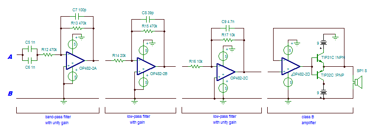
signal by a fair amount. We will also be running the signal through a band
-pass filter to only allow audible frequencies between 200Hz and 2kHz to
pass.
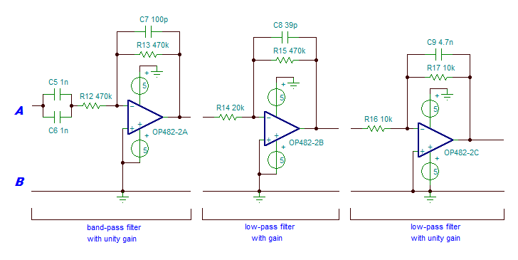
The first part is the band-pass filter. It allows only a small range of
frequencies to pass through, and in our case 200Hz to 2kHz is more than
enough. Note that because the resistors match, there is no gain here, only
filtering. We don't want to amplify noise, so let's filter it out first.
After the band-pass filter we have two low-pass filters, the first with gain
of approximately 23.5 and cutoff of about 8.6kHz, and the second with unity
gain of 1, which means no amplification, and cutoff of about 3.4kHz. Even
after the band-pass filter we still have some noise from the carrier wave
(filters aren't perfect after all) and the signal is weak. We filter out
noise above 8.6kHz and then amplify it 23.5 times. Yep, it's high but it
needs it (you can change it by changing the resistor ratio. Click the low
-pass filter link above for the equation). The second low-pass filter then
further cleans up that signal by filtering noise above 3.4kHz, which is
higher than our target range of 200Hz-2kHz, so we're good. The second filter
is not absolutely necessary, but it did make a difference in the end.
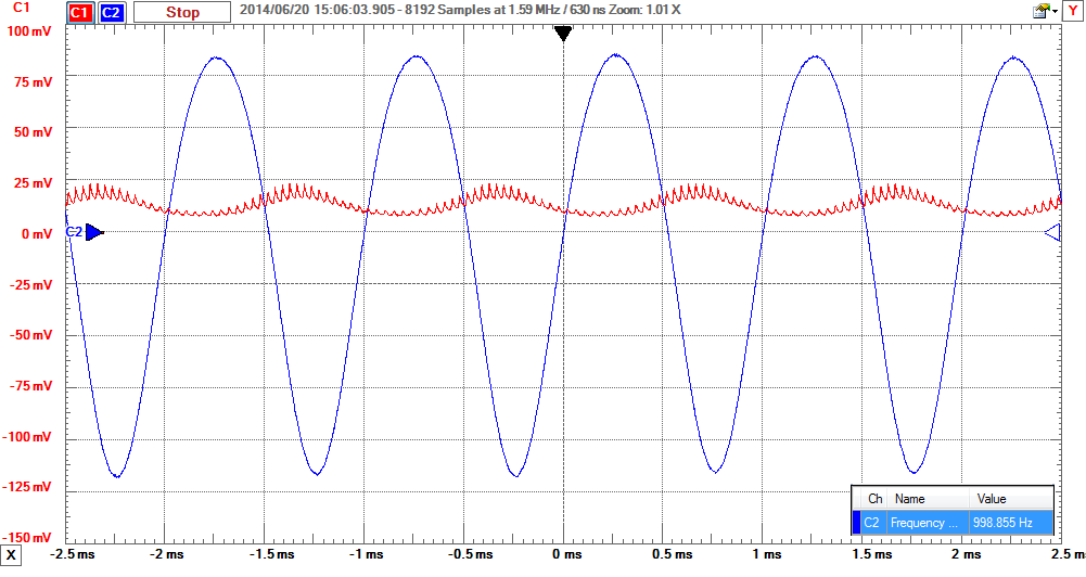
Image 4 shows the difference in the signal between the output of the
envelope detector and the output of the last filter. The scale is not
exactly the same as before, but the data was just outside of range so I
shrunk it down a little bit. Did you notice the measurement window at the
bottom right? That's the 1kHz modulation value we saw in the settings in
image 3 above. It's not a perfect sine wave, but it's a far sight cleaner
than it was before, and it's good enough that you won't notice the
difference.
If you don't want to add the class B amplifier, you're done here. Otherwise,
get yourself some 9V batteries and turn the page.
Filtering
The signal from the envelope detector doesn't have much amplitude and
contains quite a bit of noise. So we add several filters to both clarify and
boost the signal. Look at the o-scope display in image 2. The red CH 1
signal is a 25kHz carrier with a 1kHz modulation frequency, amplitude of
500mV and index of 10%. These settings are all under the advanced tab on the
Analog Discovery AWG tool (see image 3) if you would like to generate the
signal yourself. This signal then is inserted into the input of the
differentiator, bypassing the modulation circuit for now. The blue CH 2 is
the output of the envelope detector, before any filtering. Do you see the
scale on the left of the display in image 2? Each division is 20mV for CH 2.
Most scopes will let you choose different scales for each channel, and here
the scale for CH 1 is 200mV/div, larger by a factor of 10. With these two
signals on a scale of 200mV/div, you would barely be able to see the output
of the envelope detector because it is so weak. You can also see the noise
in the signal as well in image 2. We need to filter that out and amplify the
signal by a fair amount. We will also be running the signal through a band
-pass filter to only allow audible frequencies between 200Hz and 2kHz to
pass.
The first part is the band-pass filter. It allows only a small range of
frequencies to pass through, and in our case 200Hz to 2kHz is more than
enough. Note that because the resistors match, there is no gain here, only
filtering. We don't want to amplify noise, so let's filter it out first.
After the band-pass filter we have two low-pass filters, the first with gain
of approximately 23.5 and cutoff of about 8.6kHz, and the second with unity
gain of 1, which means no amplification, and cutoff of about 3.4kHz. Even
after the band-pass filter we still have some noise from the carrier wave
(filters aren't perfect after all) and the signal is weak. We filter out
noise above 8.6kHz and then amplify it 23.5 times. Yep, it's high but it
needs it (you can change it by changing the resistor ratio. Click the low
-pass filter link above for the equation). The second low-pass filter then
further cleans up that signal by filtering noise above 3.4kHz, which is
higher than our target range of 200Hz-2kHz, so we're good. The second filter
is not absolutely necessary, but it did make a difference in the end.
Image 4 shows the difference in the signal between the output of the
envelope detector and the output of the last filter. The scale is not
exactly the same as before, but the data was just outside of range so I
shrunk it down a little bit. Did you notice the measurement window at the
bottom right? That's the 1kHz modulation value we saw in the settings in
image 3 above. It's not a perfect sine wave, but it's a far sight cleaner
than it was before, and it's good enough that you won't notice the
difference.
If you don't want to add the class B amplifier, you're done here. Otherwise,
get yourself some 9V batteries and turn the page.
Step 6: Amplifying the Signal
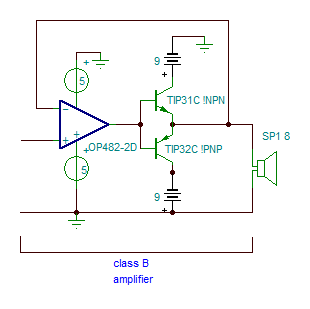
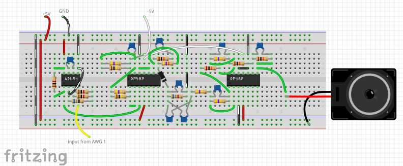
 Amplifying the Signal
3 More Images
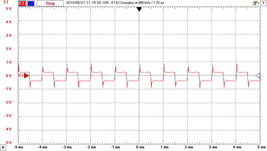
The 9 V batteries and connectors are not included with the Analog Parts Kit,
and it is not absolutely necessary to amplify the signal coming from the
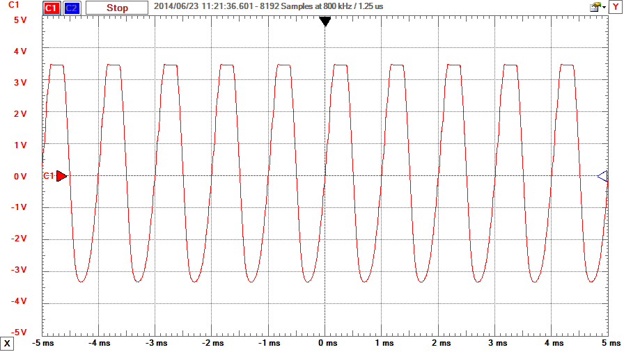
last low-pass filter. However, as you can see from comparing images 2 and 3,
the signal will clip when you add the speaker and form more of a square wave
than a sine wave. A small 8-Ohm speaker will clip even more. This happens
because the speaker itself also has a transfer function that must be
accounted for, which is a fancy way of saying that it is trying to draw too
much current at peak voltage, so it clips the voltage. It will actually
sound louder, but won't be as clear. Adding the amplifier allows more
current to be available and that allows the voltage level at the speaker
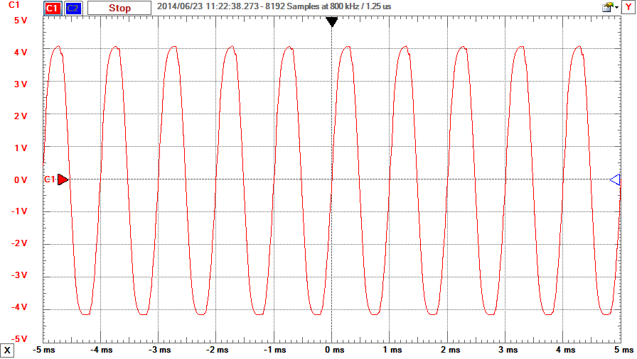
match the output level at the last filter. Image 4 shows the signal with the
amplifier in place and the speaker attached. The difference is minimal this
time. I've used this on a 4-inch computer speaker I salvaged and even a 6
-inch woofer and they all worked with this amplifier. Just remember that
larger speakers require more current so you will drain your batteries
faster.
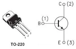
When putting the BJTs on the breadboard it is very easy to get the pins
mixed up. I've built this circuit, start to finish, at least half a dozen
times, and I still did it. Again. I've included the pin-out diagram for them
(they have the same B/C/E pin assignments), so good luck.
Amplifying the Signal
3 More Images
The 9 V batteries and connectors are not included with the Analog Parts Kit,
and it is not absolutely necessary to amplify the signal coming from the
last low-pass filter. However, as you can see from comparing images 2 and 3,
the signal will clip when you add the speaker and form more of a square wave
than a sine wave. A small 8-Ohm speaker will clip even more. This happens
because the speaker itself also has a transfer function that must be
accounted for, which is a fancy way of saying that it is trying to draw too
much current at peak voltage, so it clips the voltage. It will actually
sound louder, but won't be as clear. Adding the amplifier allows more
current to be available and that allows the voltage level at the speaker
match the output level at the last filter. Image 4 shows the signal with the
amplifier in place and the speaker attached. The difference is minimal this
time. I've used this on a 4-inch computer speaker I salvaged and even a 6
-inch woofer and they all worked with this amplifier. Just remember that
larger speakers require more current so you will drain your batteries
faster.
When putting the BJTs on the breadboard it is very easy to get the pins
mixed up. I've built this circuit, start to finish, at least half a dozen
times, and I still did it. Again. I've included the pin-out diagram for them
(they have the same B/C/E pin assignments), so good luck.
Step 7: Testing
 Testing
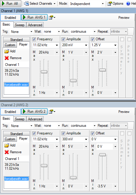
Now let's do some testing to verify. If you haven't yet downloaded a short
.wav file, do so now. Go into the AWG tool settings and check both channels
to turn them both on. Click on the 'player' tab, then on 'add'. A window
will come up to allow you to find the downloaded .wav file. Double click on
it to load it. Notice the playback frequency in the window to the left? My
file is set at 11.02kHz. For now, set the AWG channels to playback at this
frequency. You won't break anything if you change it, it just changes the
playback speed of the file. Load the file for both AWG channels. There are
notes on the image that will help clarify this step.
Set the channels according to image 1, making sure that the offset for CH 1
is 1.25V. It will make a big difference and took me a while to troubleshoot
the first time. The amplitude (volume) settings are not super critical, but
remember that we are amplifying the signal by quite a lot in the circuit, so
start smaller and work your way up as desired.
Start with CH 2 on the AWG and plug the yellow/white wire directly into the
speaker, bypassing the entire circuit. This way you can hear the file
playback on the speaker before passing it through the circuit. Once you have
it playing on the speaker using CH 2, plug CH 1 into pin 4 of the AD654.
Unplug AWG CH 2 from the speaker and connect the output of the class B
amplifier to the speaker. You should hear the same playback either way.
And there you have it. Please don't hesitate to ask questions, either in the
comments below or PM. Have fun building!
Testing
Now let's do some testing to verify. If you haven't yet downloaded a short
.wav file, do so now. Go into the AWG tool settings and check both channels
to turn them both on. Click on the 'player' tab, then on 'add'. A window
will come up to allow you to find the downloaded .wav file. Double click on
it to load it. Notice the playback frequency in the window to the left? My
file is set at 11.02kHz. For now, set the AWG channels to playback at this
frequency. You won't break anything if you change it, it just changes the
playback speed of the file. Load the file for both AWG channels. There are
notes on the image that will help clarify this step.
Set the channels according to image 1, making sure that the offset for CH 1
is 1.25V. It will make a big difference and took me a while to troubleshoot
the first time. The amplitude (volume) settings are not super critical, but
remember that we are amplifying the signal by quite a lot in the circuit, so
start smaller and work your way up as desired.
Start with CH 2 on the AWG and plug the yellow/white wire directly into the
speaker, bypassing the entire circuit. This way you can hear the file
playback on the speaker before passing it through the circuit. Once you have
it playing on the speaker using CH 2, plug CH 1 into pin 4 of the AD654.
Unplug AWG CH 2 from the speaker and connect the output of the class B
amplifier to the speaker. You should hear the same playback either way.
And there you have it. Please don't hesitate to ask questions, either in the
comments below or PM. Have fun building!