Metal Detector #2
From: https://www.nutsvolts.com/magazine/article/
build_a_four_transistor_metal_detector
Build A Four Transistor Metal Detector
 By Paul Florian
» Skip to the Extras
Want to be a treasure hunter? By discerning subtle changes in frequency,
this design is capable of detecting coins to a depth of three to four
inches.
The circuit can sense a soda can at a depth of six inches and metal pipes at
an even greater distance. The unit is powered by two 9V batteries in series.
The detector has a current draw of approximately 9 mA at 18 VDC. As a
result, the batteries should last a long time.
By Paul Florian
» Skip to the Extras
Want to be a treasure hunter? By discerning subtle changes in frequency,
this design is capable of detecting coins to a depth of three to four
inches.
The circuit can sense a soda can at a depth of six inches and metal pipes at
an even greater distance. The unit is powered by two 9V batteries in series.
The detector has a current draw of approximately 9 mA at 18 VDC. As a
result, the batteries should last a long time.
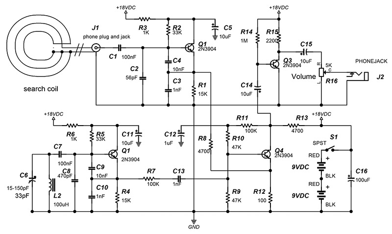 FIGURE 1. Four Transistor Metal Detector Schematic.
Theory
The design consists of four parts:
- Q1 forms an oscillator whose frequency is determined by L1.
- Q2 is a reference oscillator whose frequency is set by C6.
- Q3 is a mixer that multiplies the outputs of Q1 and Q2.
- Q4 is a simple one transistor amplifier.
L1 needs to be 100 μH. This inductor is created from 22 turns of 22 gauge
magnet wire on a four inch diameter coil form (see Reference). However, I
wound the coil with 21 turns, resulting in an inductance of 88 mH. The
inductance measured into the phono cable with the search coil connected is
126 μH. In order to work properly, you must use the audio cable specified
in the Parts List. The resonant frequency is F = 1 / (2π*SQR(L1*C)). C= 1
nF in series with 10 nF + 56 pF. Solving yields C = 965 pF. Calculating for
F gives 456 kHz. Therefore, the oscillation frequency of Q1 is 456 kHz when
no metal object is near the coil L1.
The oscillator formed by Q2 is the reference oscillator. This frequency can
be changed by adjusting C6. The output must be set within 2 kHz of Q1’s
output frequency. To obtain this result you may have to use a slightly
different capacitor for C8. The part I used has a tolerance of ±20%. Note
that the oscillation frequency of Q1 is very sensitive to stray
capacitance.
The output of Q1 will vary about 70 Hz per each picofarad change of stray
capacitance. Transistor Q4 forms a mixer. Q1 and Q2 both feed signals into
this circuit. When a metallic object is close to the search coil, the
inductance of L1 decreases. This causes Q1’s oscillation frequency to
increase. The output of the mixer is the sum and magnitude of the difference
of the two signals: Fosc + Fref and |Fosc - Fref| (where “|x|” means
“absolute value of x”).
Suppose Fref = 500 kHz and Fosc = 501 kHz. The output of the mixer will be 1
kHz and 1,001 kHz. If Fref = 500 kHz and Fosc = 499 kHz, the output of Q4 is
1 kHz and 999 kHz. The frequencies output by the mixer feed a high input
impedance BJT amplifier formed by Q3. The output of Q3 is capacitively
coupled to the volume control R16.
The earphone used in this application must have a high impedance. The
ceramic earphone specified in the Parts List has a 20 megohm impedance and
works well. Note that both the high land low mixer frequencies are sent to
the earphone. The earpiece shunts the higher frequency to ground, acting as
a low-pass filter.
Construction
The circuit was built on a 2.6” x 3.5” piece of perfboard cut from PC
board specified in the Parts List. Make a copy of the schematic and cross
off the components as they are installed. An adapter was used to mount C6
(refer to Photo 1).
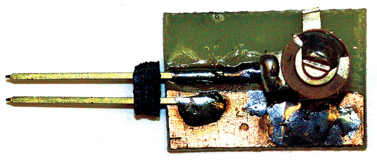 PHOTO 1. C6 Adapter PCB.
To construct the board, cut a 1/2” by 3/4” piece of double or single
sided PCB material. Use a permanent marker to mask the areas where the
traces should go. Then, etch the board and clean the ink off with rubbing
alcohol. Finally, solder the capacitor and SIP pins to the PCB in surface
-mount fashion.
This adapter plugs into a two position SIP socket on the PCB. The pins of
the adapter can be bent to 90 degrees for top adjustment. The volume control
(R16) pin designations are shown in Figure 4.
PHOTO 1. C6 Adapter PCB.
To construct the board, cut a 1/2” by 3/4” piece of double or single
sided PCB material. Use a permanent marker to mask the areas where the
traces should go. Then, etch the board and clean the ink off with rubbing
alcohol. Finally, solder the capacitor and SIP pins to the PCB in surface
-mount fashion.
This adapter plugs into a two position SIP socket on the PCB. The pins of
the adapter can be bent to 90 degrees for top adjustment. The volume control
(R16) pin designations are shown in Figure 4.
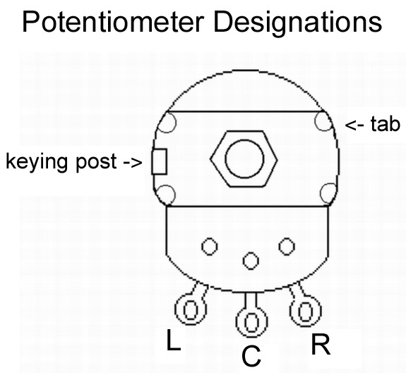 FIGURE 4. Potentiometer pin designations.
\Break off the keying post of R16 with a pair of pliers. Instead of
soldering the connecting wires directly to the PCB, .100” male headers are
used. These headers are installed for the search coil, volume, S1, earphone,
and 18 VDC. Female crimp housing connectors are used to make the twisted
pair cable assemblies shown in Table 1.
FIGURE 4. Potentiometer pin designations.
\Break off the keying post of R16 with a pair of pliers. Instead of
soldering the connecting wires directly to the PCB, .100” male headers are
used. These headers are installed for the search coil, volume, S1, earphone,
and 18 VDC. Female crimp housing connectors are used to make the twisted
pair cable assemblies shown in Table 1.
| Source (Crimp Housing) | # of Pins | Destination | Wire Type
|
| COIL (L1) | 2 | J1 RCA Jack | Shielded Cable
|
| VOL | 3 | R16 | Twisted Trio
|
| EAR | 2 | Phone Jack | Twisted Pair
|
| S1 | 2 | SPST Switch | Twisted Pair
|
| 18 VDC | 2 | 9V Battery Snaps in Series | Battery Leads
|
TABLE 1.
Be sure to note the ground pin on the COIL, VOL, EAR, and 18 VDC connectors.
An easy way to do this is to make the ground connections with a black wire
in the cable assemblies. Keep the cable to the RCA jack as short as possible
to reduce stray capacitance.
To construct the search coil, obtain a 1X copy of Figure 2 (Search Coil
Form). Use the template to cut a form from the wood slat given in the Parts
List. Drill the six holes 5/32“ in diameter.
 FIGURE 2. Search coil form.
Now construct the wire coil. Wrap 21 turns of 22 gauge solid magnet wire
around a 4“ diameter tube (an oatmeal container works nicely). Once the
coil is wound, wrap it in electrical tape (see Photo 2).
FIGURE 2. Search coil form.
Now construct the wire coil. Wrap 21 turns of 22 gauge solid magnet wire
around a 4“ diameter tube (an oatmeal container works nicely). Once the
coil is wound, wrap it in electrical tape (see Photo 2).
 PHOTO 2. Coil assembly.
Wrap 1” strips of aluminum foil around the coil, leaving space for the two
magnet wire leads. Strip three inches of insulation from a six inch red 22
gauge solid wire. Wrap the three inch bare end of this wire around the
aluminum foil (see Photo 3). Wrap the whole coil assembly with electrical
tape.
PHOTO 2. Coil assembly.
Wrap 1” strips of aluminum foil around the coil, leaving space for the two
magnet wire leads. Strip three inches of insulation from a six inch red 22
gauge solid wire. Wrap the three inch bare end of this wire around the
aluminum foil (see Photo 3). Wrap the whole coil assembly with electrical
tape.
 PHOTO 3. Shielded coil assembly.
Make the search coil strain relief bracket from a piece of aluminum sheet
PHOTO 3. Shielded coil assembly.
Make the search coil strain relief bracket from a piece of aluminum sheet
 (Figure 3).
FIGURE 3. Search coil RCA cable strain relief.
A 1/4” grommet is installed in the 1/4” hole. Cut off one end of the RCA
cable and feed it through the grommet. Remove 1” of insulation from the
end of the RCA cable. Cut the red wire from the search coil to 1/2” long
and strip the insulation to 1/4“. Scrape the enamel from the magnet wires
with a razor knife and tin with solder.
Solder the magnet wire adjacent to the red wire along with the red wire to
the shield connection of the RCA cable. The other magnet wire is soldered to
the center conductor of the RCA cable. The solder connections should be less
than 1/2” and carefully wrapped with electrical tape or the output of the
mixer may drift.
Next, mount the strain relief bracket to the wood slat with a 1/2” 6-32
machine screw, two external tooth lock washers, and a 6-32 nylon lock nut.
The coil is mounted to the coil form with three wire ties. Finally, attach
the 45 degree 7/8” inside diameter PVC elbow fitting to the coil form with
two #6 x 1/2” sheet metal screws. You must first drill 3/32” pilot holes
in the PVC joint to receive the screws. This 45 degree fitting receives one
end of the metal detector shaft (a 33” long piece of PVC tubing).
A photo of the completed search coil assembly with the bracket is shown in
(Figure 3).
FIGURE 3. Search coil RCA cable strain relief.
A 1/4” grommet is installed in the 1/4” hole. Cut off one end of the RCA
cable and feed it through the grommet. Remove 1” of insulation from the
end of the RCA cable. Cut the red wire from the search coil to 1/2” long
and strip the insulation to 1/4“. Scrape the enamel from the magnet wires
with a razor knife and tin with solder.
Solder the magnet wire adjacent to the red wire along with the red wire to
the shield connection of the RCA cable. The other magnet wire is soldered to
the center conductor of the RCA cable. The solder connections should be less
than 1/2” and carefully wrapped with electrical tape or the output of the
mixer may drift.
Next, mount the strain relief bracket to the wood slat with a 1/2” 6-32
machine screw, two external tooth lock washers, and a 6-32 nylon lock nut.
The coil is mounted to the coil form with three wire ties. Finally, attach
the 45 degree 7/8” inside diameter PVC elbow fitting to the coil form with
two #6 x 1/2” sheet metal screws. You must first drill 3/32” pilot holes
in the PVC joint to receive the screws. This 45 degree fitting receives one
end of the metal detector shaft (a 33” long piece of PVC tubing).
A photo of the completed search coil assembly with the bracket is shown in
 Photo 5. PHOTO 5. Search coil assembly with bracket.
Two 10” and one 3.5” lengths of 7/8” diameter PVC pipe are used when
making the handle for the metal detector. Refer to Photo 4 for assembly.
Photo 5. PHOTO 5. Search coil assembly with bracket.
Two 10” and one 3.5” lengths of 7/8” diameter PVC pipe are used when
making the handle for the metal detector. Refer to Photo 4 for assembly.
 PHOTO 4. PVC handle assembly.
The handle uses two 90 degree elbows and one 45 degree elbow. Two 5/32”
pilot holes and #10 1/2” sheet metal screws are used when connecting each
of these elbow joints to the PVC pipes.
Drill two 5/32“ holes in the bottom of the case as shown in Photo 6. These
holes are used to attach the enclosure to the handle assembly.
PHOTO 4. PVC handle assembly.
The handle uses two 90 degree elbows and one 45 degree elbow. Two 5/32”
pilot holes and #10 1/2” sheet metal screws are used when connecting each
of these elbow joints to the PVC pipes.
Drill two 5/32“ holes in the bottom of the case as shown in Photo 6. These
holes are used to attach the enclosure to the handle assembly.
 PHOTO 6. View of open case.
Use Photo 7 as a reference when mounting the following items to the front
panel: J2, S1, and R16. Drill appropriately sized holes in the lid for these
items.
PHOTO 6. View of open case.
Use Photo 7 as a reference when mounting the following items to the front
panel: J2, S1, and R16. Drill appropriately sized holes in the lid for these
items.
 PHOTO 7. Front panel view.
Next, drill a hole for J1 next to the 45 degree elbow joint where the 33”
PVC pipe shaft attaches to the handle. Separate the lower and upper 10”
lengths of PVC pipe. Drill mounting holes in the lower 10” piece of PVC
pipe to match the holes in the bottom of the case drilled earlier and mount
it with two 1-1/4” 8-32 machine screws, external lock washers, and nuts.
Install J2, S1, and R16 on the housing lid. Attach J1 to the case. Screw the
PCB to the front panel with four nylon 4-40 1/2” threaded spacers and
eight 4-40 screws. Connect the previously mentioned crimp housing cables
between their sources and destinations. Attach the two 9V battery holders to
the bottom of the case with double-sided adhesive tape.
Now, reassemble the upper and lower 10” PVC pipe sections. Insert the
33” main shaft into the handle assembly’s 45 degree elbow joint, drill a
pilot hole, and secure with a #10 1/2” screw. The cap at the end of the
handle is press-fit. Similarly, the search coil assembly is press-fit to the
end of the 33” metal detector shaft.
PHOTO 7. Front panel view.
Next, drill a hole for J1 next to the 45 degree elbow joint where the 33”
PVC pipe shaft attaches to the handle. Separate the lower and upper 10”
lengths of PVC pipe. Drill mounting holes in the lower 10” piece of PVC
pipe to match the holes in the bottom of the case drilled earlier and mount
it with two 1-1/4” 8-32 machine screws, external lock washers, and nuts.
Install J2, S1, and R16 on the housing lid. Attach J1 to the case. Screw the
PCB to the front panel with four nylon 4-40 1/2” threaded spacers and
eight 4-40 screws. Connect the previously mentioned crimp housing cables
between their sources and destinations. Attach the two 9V battery holders to
the bottom of the case with double-sided adhesive tape.
Now, reassemble the upper and lower 10” PVC pipe sections. Insert the
33” main shaft into the handle assembly’s 45 degree elbow joint, drill a
pilot hole, and secure with a #10 1/2” screw. The cap at the end of the
handle is press-fit. Similarly, the search coil assembly is press-fit to the
end of the 33” metal detector shaft.
Use
Once the PCB, search coil, housing, and handle assemblies have been made,
follow these steps:
- Plug the RCA cable from the search coil bracket to the metal detector
housing RCA jack. Wrap the excess cable in spiral fashion along the length
of the metal detector’s shaft and secure with electrical tape. This will
keep the cable from moving and causing a subsequent change in stray
capacitance.
- Plug the ceramic earphone into J2.
- Turn the volume control completely clockwise.
- Attach the two 9V batteries to the battery snaps and install the
batteries into the holders.
- Verify that S1 is in the On position.
You should hear a tone from the earpiece. The pitch at the earphone should
increase when the search coil approaches a metal object. To obtain this
result, make sure that no metal object is near the search coil and then turn
C6 clockwise so that the pitch is a high tone, followed by a decreasing tone
until the earphone is silent. Next, rotate C6 counter-clockwise until a
frequency of approximately 2 kHz is reached. As mentioned before, if you are
unable to tune the unit as specified, try reducing the value of C8.
Now that the tone has been set, attach the lid to the case with the four
screws provided. If the metal detector does not balance properly, you may
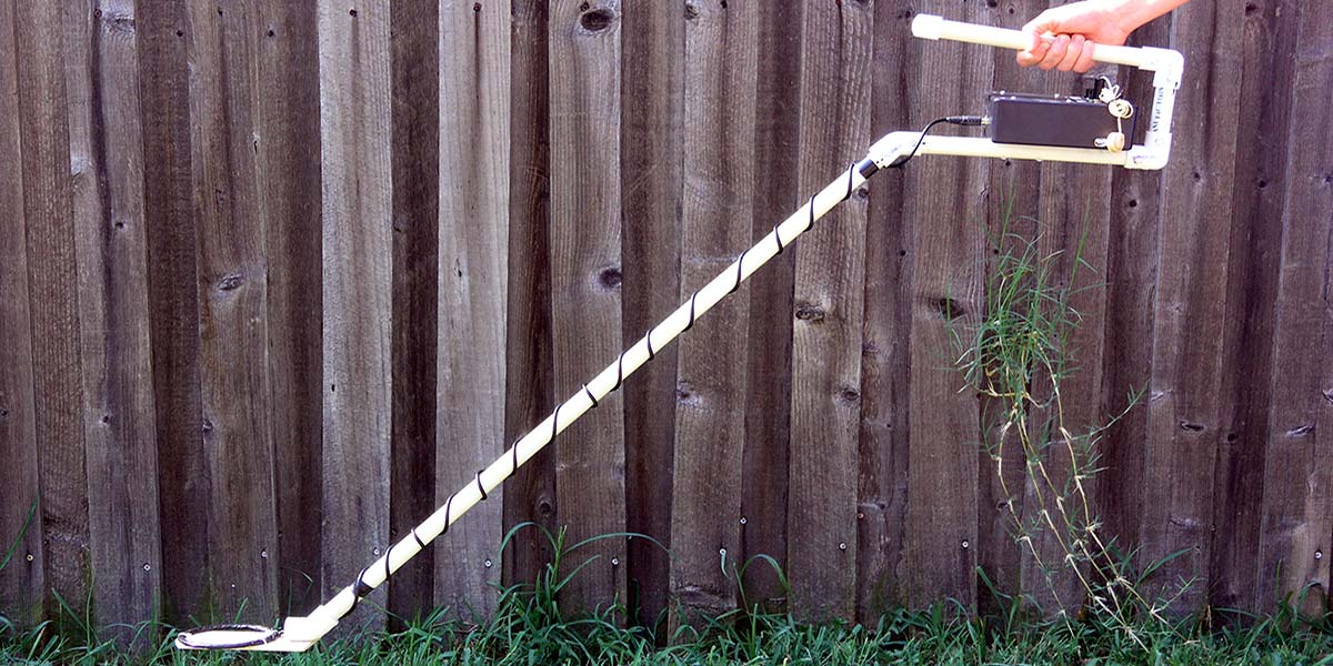
want to decrease the main shaft length to less than 33”. Photo 8 shows the
finished metal detector.
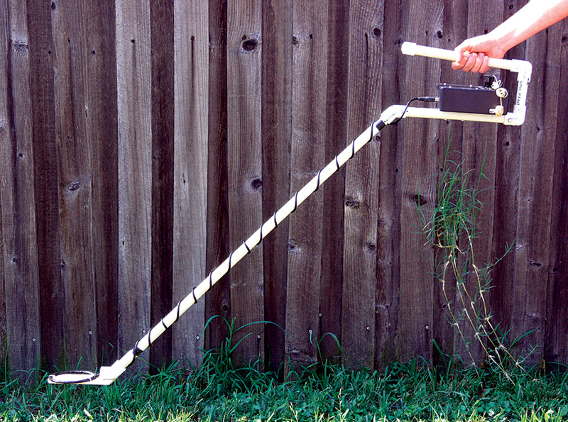 PHOTO 8. Completed metal detector.
After the unit has been tested and completely assembled, it’s time to look
for coins and jewelry! Good places to find coins at shallow depths are under
the swings at a playground and below bleachers. For very large metal objects
at close distances, the output pitch of the metal detector may be higher
than physically audible. Happy hunting with your four transistor metal
detector! NV
PHOTO 8. Completed metal detector.
After the unit has been tested and completely assembled, it’s time to look
for coins and jewelry! Good places to find coins at shallow depths are under
the swings at a playground and below bleachers. For very large metal objects
at close distances, the output pitch of the metal detector may be higher
than physically audible. Happy hunting with your four transistor metal
detector! NV
Reference
R. Dean Straw, N6BV, The ARRL Handbook, “Calculating Practical
Inductors,” 1999, p. 6-22, The American Radio Relay League.
| Parts List
|
| Item | DESCRIPTION
|
| R1, R4 | 15K 5% 1/4W | |
|
| R2, R5 | 33K 5% 1/4W | |
|
| R3, R6 | 1K 5% 1/4W | |
|
| R7, R11 | 100K 5% 1/4W | |
|
| R8, R13 | 4.7K 5% 1/4W | |
|
| R9, R10 | 47K 5% 1/4W | |
|
| R12 | 100 5% 1/W | |
|
| R14 | 1M 5% 1/4W | |
|
| R15 | 2.2K 5% 1/4W | |
|
| R16 | 5K audio taper pot | |
|
| C1, C7 | 100 nF 50V ±10% | |
|
| C4, C9 | 10 nF 50V ±10% | |
|
| C3, C10, C13 | 1 nF 50V ±10% | |
|
| C2 | 56 pF 100V ±20% | |
|
| C8 | 470 pF 100V ±20% | |
|
| C5, C11, C14-15 | 10 µF 50V ±20% | |
|
| C12 | 1 µF 50V ±20% | |
|
| C6 | 15-150 pF variable cap | |
|
| L1 | See text | |
|
| L2 | 100 µH ±5% | |
|
| Q1-Q4 | 2N3904 transistor | |
|
| J1 | RCA jack | |
|
| J2 | 3.5 mm phone jack | |
|
| S1 | SPST switch | |
|
| Aluminum sheet | K&S Metals | |
|
| Wood slats | Forster 6-Count Slats | |
|
| PVC pipe | 6’ 7/8” OD PVC Pipe | |
|
| Audio cable | 6 ft cable | |
|
| Case | 6 x 4 x 2 | |
|
| Battery snap | 9V snap (2) | |
|
| Earpiece | Ceramic earphone | |
|
| PCB | Prototype board | |
|
| Battery holder | 9V holder (2) | |
|
| Tape | Two-sided adhesive tape | |
|
| Batteries | 2 x 9 VDC
|