Arduino Metal Detector #1

From:   https://www.allaboutcircuits.com/projects/metal-detector-with-arduino/
github: https://github.com/evankale/ArduinoMetalDetector
Build Your Own Metal Detector with an Arduino
October 03, 2016 by Evan Kale
Building a metal detector using a Colpitts oscillator and an Arduino.
Learn how to build a metal detector using a Colpitts oscillator and an Arduino.
How Do Metal Detectors Work?
Tank circuit
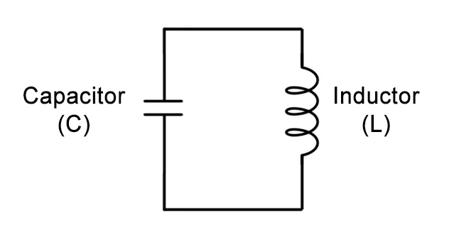 The tank circuit
In the above circuit, the series capacitor and inductor form a tank circuit.
In a tank circuit, energy is transferred repeatedly between a capacitor and
an inductor, resulting in oscillation. Current discharged from the capacitor
flows through the inductor; when the capacitor is completely discharged, the
inductor's decreasing magnetic field maintains the current flow. The
capacitor will then charge with the opposite polarity, and when the magnetic
field has completely collapsed, the capacitor will discharge, resulting in
current flow in the direction opposite to that of the original current.
This cycle continues.
The inductor of the above tank circuit forms the detector of the metal
detector( a large coil of wire). When metallic material approaches the
center of the inductor( the detector coil), it enters the magnetic field
created by the inductor. This changes the magnetic permeability of the
inductor’s core, causing the inductance to change. The change in
inductance, in turn, changes the oscillating frequency of the tank circuit.
If the components were ideal, the tank circuit would oscillate indefinitely
without an external power source. But, in practice, the components are non
-ideal. The unwanted resistance of the components will introduce energy
loss, causing the oscillating current to taper to a stop. To counter this, a
single stage BJT inverting amplifier is used to continuously add gain into
the tank circuit.
Colpitts oscillator
The tank circuit
In the above circuit, the series capacitor and inductor form a tank circuit.
In a tank circuit, energy is transferred repeatedly between a capacitor and
an inductor, resulting in oscillation. Current discharged from the capacitor
flows through the inductor; when the capacitor is completely discharged, the
inductor's decreasing magnetic field maintains the current flow. The
capacitor will then charge with the opposite polarity, and when the magnetic
field has completely collapsed, the capacitor will discharge, resulting in
current flow in the direction opposite to that of the original current.
This cycle continues.
The inductor of the above tank circuit forms the detector of the metal
detector( a large coil of wire). When metallic material approaches the
center of the inductor( the detector coil), it enters the magnetic field
created by the inductor. This changes the magnetic permeability of the
inductor’s core, causing the inductance to change. The change in
inductance, in turn, changes the oscillating frequency of the tank circuit.
If the components were ideal, the tank circuit would oscillate indefinitely
without an external power source. But, in practice, the components are non
-ideal. The unwanted resistance of the components will introduce energy
loss, causing the oscillating current to taper to a stop. To counter this, a
single stage BJT inverting amplifier is used to continuously add gain into
the tank circuit.
Colpitts oscillator
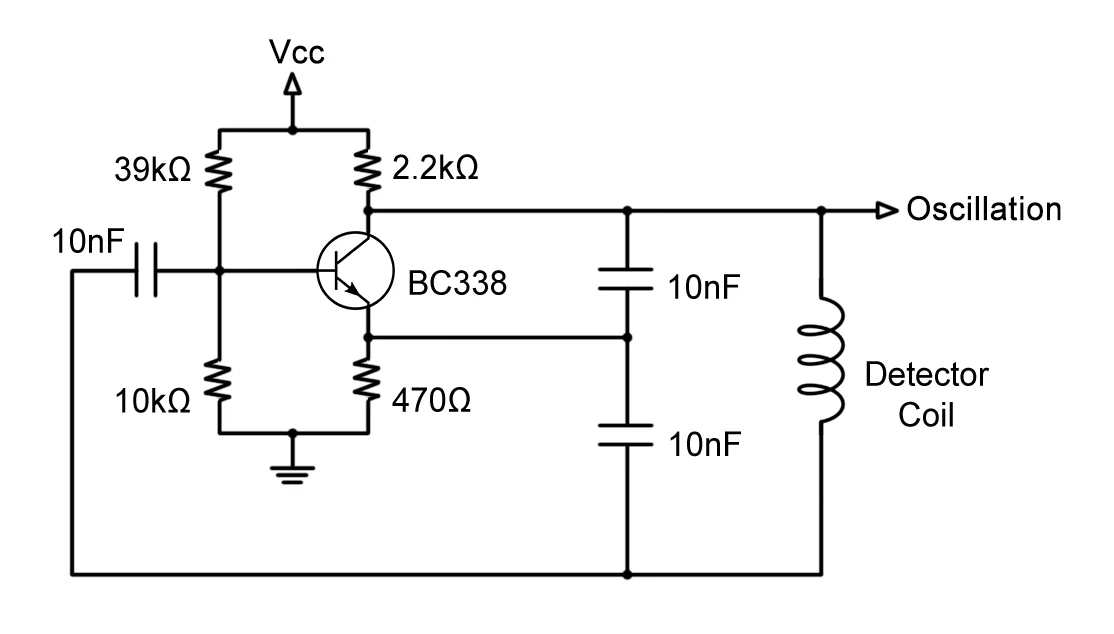 The Colpitts oscillator
Since the oscillation at the nodes before and after the inductor are 180°
out of phase of with each other, one of the nodes will supply the
oscillation to the transistor base, amplify and invert the signal at the
collector, then return it in phase to the other node of the tank circuit.
This entire circuit is called the Colpitts oscillator.
The Colpitts oscillator above provides a steady oscillation with a frequency
in the 100kHz range. Metals from household items changing the permeability
of the inductor core will fluctuate this frequency around 10kHz. Since this
frequency range is outside of the human audio spectrum( 20Hz to 20kHz), we
will need to translate the oscillation into an audible tone.
Traditional BFO( beat-frequency oscillator) metal detectors overcome this
problem by incorporating another tank circuit with a fixed frequency equal
to the frequency of the detector tank circuit without the influence of any
metals. Then, taking the difference between the two frequencies will isolate
the fluctuating frequencies of the detector circuit and bring it down to an
audible range.
For this metal detector project, we will be using an Arduino to process the
oscillation signal instead of offsetting the oscillation with a second tank
circuit. The Arduino will store the fixed frequency and continuously compare
the incoming frequency of the detector circuit with the stored frequency
(more on the Arduino program below).
The Colpitts oscillator
Since the oscillation at the nodes before and after the inductor are 180°
out of phase of with each other, one of the nodes will supply the
oscillation to the transistor base, amplify and invert the signal at the
collector, then return it in phase to the other node of the tank circuit.
This entire circuit is called the Colpitts oscillator.
The Colpitts oscillator above provides a steady oscillation with a frequency
in the 100kHz range. Metals from household items changing the permeability
of the inductor core will fluctuate this frequency around 10kHz. Since this
frequency range is outside of the human audio spectrum( 20Hz to 20kHz), we
will need to translate the oscillation into an audible tone.
Traditional BFO( beat-frequency oscillator) metal detectors overcome this
problem by incorporating another tank circuit with a fixed frequency equal
to the frequency of the detector tank circuit without the influence of any
metals. Then, taking the difference between the two frequencies will isolate
the fluctuating frequencies of the detector circuit and bring it down to an
audible range.
For this metal detector project, we will be using an Arduino to process the
oscillation signal instead of offsetting the oscillation with a second tank
circuit. The Arduino will store the fixed frequency and continuously compare
the incoming frequency of the detector circuit with the stored frequency
(more on the Arduino program below).
Materials for your DIY Metal Detector
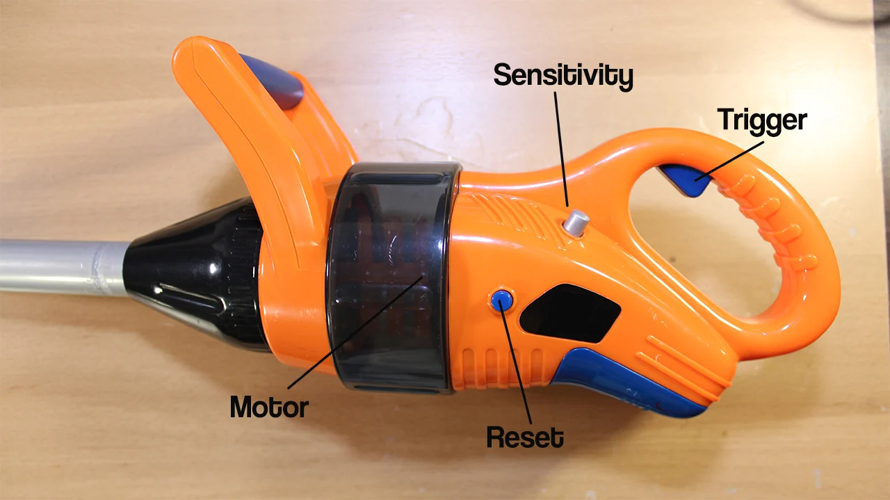 Weed-whacker toy
For this project, a toy weed-whacker was chosen to house all the components.
It includes the following features:
Weed-whacker toy
For this project, a toy weed-whacker was chosen to house all the components.
It includes the following features:
- a trigger button, which we will repurpose to trigger the speaker
- a side button, which we will use to set the fixed frequency
- a battery compartment( 3xAA batteries) with an ON/OFF switch
- a speaker, which we will play the tone through
- a motor with LEDs attached which we will be activated when the frequency
difference exceeds a certain threshold
- a circular head where we will fit a coil of wire into for the inductor of
the tank circuit
We will also add a potentiometer (silver) to make the sensitivity of the tone
changes adjustable.
 Detector coil
The inductor coil is made from approximately 50 wraps of 26 AWG wire around
a spool of 5.5 inches in diameter.
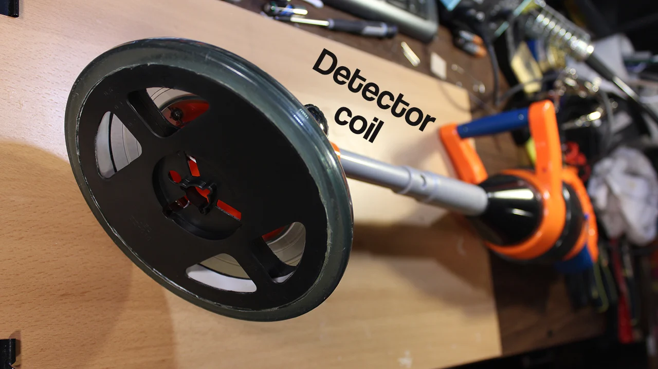
Detector coil
The inductor coil is made from approximately 50 wraps of 26 AWG wire around
a spool of 5.5 inches in diameter.
 Inside the housing
, we will replace the original circuit board with our own
circuit and attach all the peripherals to the circuit with pin headers.
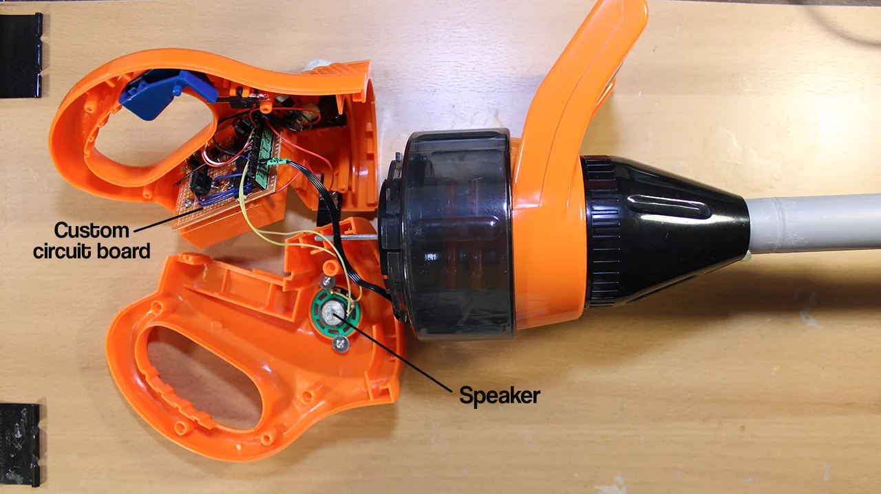
Inside the housing
Inside the housing, we will replace the original circuit board with our own
circuit and attach all the peripherals to the circuit with pin headers.
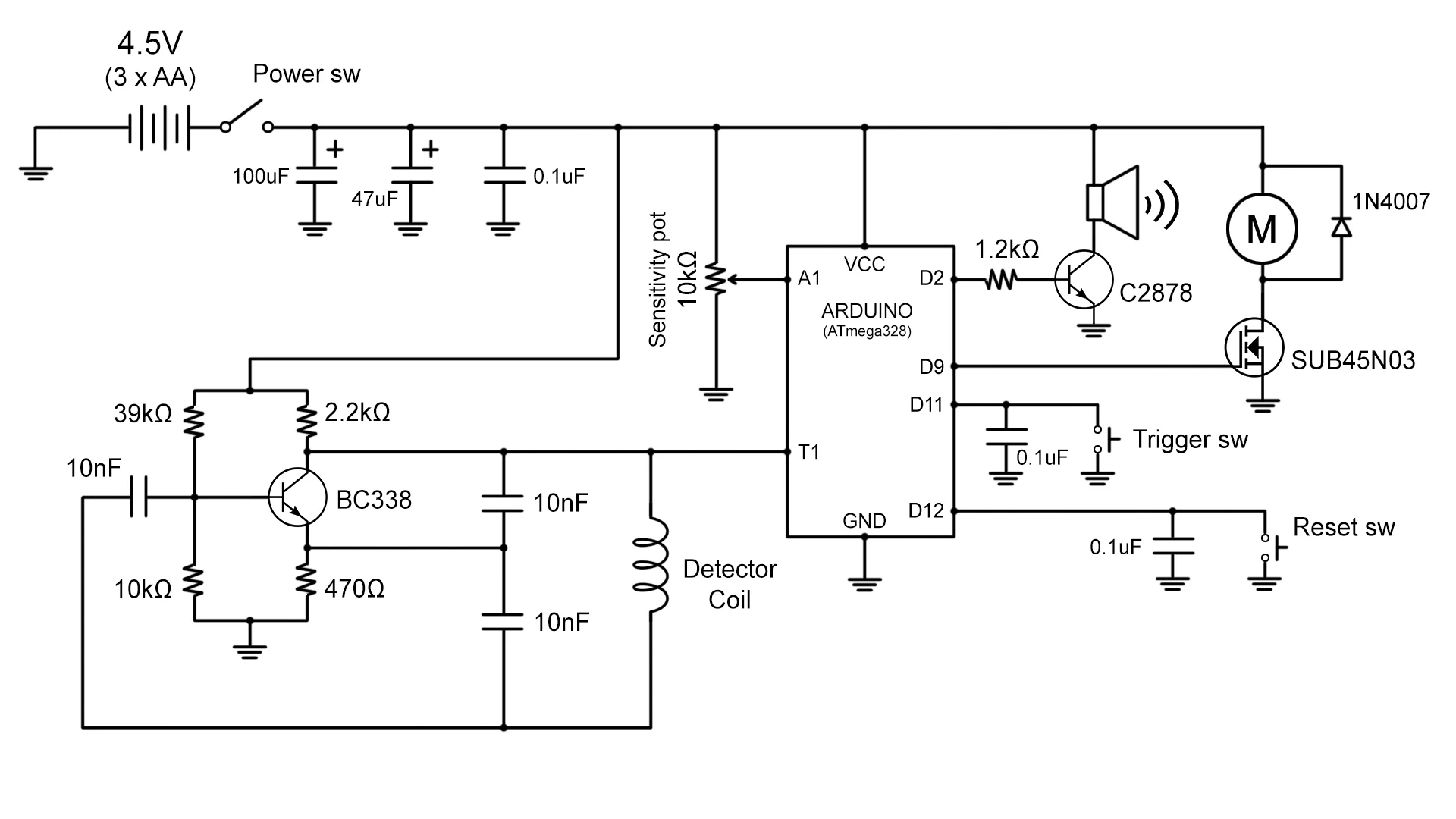
Metal Detection Circuit Schematics
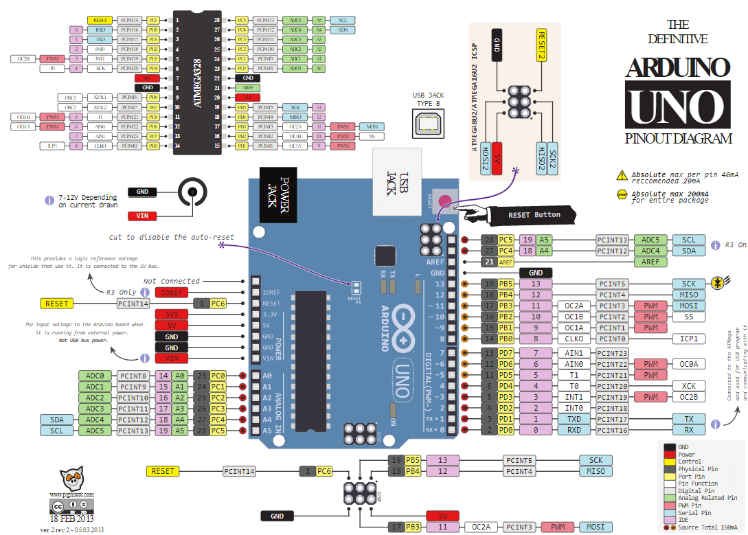
I used an Arduino UNO to program a DIP ATMega328. I then removed the
ATMega328 from the development board and embedded into a perfboard along
with the rest of the circuit.
The Colpitts oscillator, on the bottom left on the diagram, feeds the
oscillation into counter 1( pin T1) of the chip( marked as digital pin 5 on
the Arduino UNO), where it constantly counts the frequency of oscillation.
On the top level of the diagram, a power supply of 4.5V( 3xAA batteries,
with bypass capacitors) is used to power the ATmega328, oscillator, speaker,
and motor( with LEDs).
To keep the current draw of the microcontroller’s digital pins at a safe
level( 40 mA per pin maximum for the ATmega328), an NPN transistor( C2878)
is used to drive the speaker, and an N-channel MOSFET( SUB45N03) to drive
the motor.
Both the trigger and reset( sets fixed frequency) switches are wired to
digital pins using internal pull-up configuration. Small capacitors are
added in parallel to debounce the switches.
The sensitivity potentiometer is set up as a voltage divider, and the
division is read using an analog pin.
Code Walkthrough
The full source code for this project can be found here:
Below is a detailed walkthrough of the code.
Setup Function
To keep track of the detector oscillation frequency through timer counter 1,
we first need to configure the timer/counter controller registers (TCCR).
These TCCRs are accessed through the three integers: TTCR1A, TTCR1B, and TTCR1C.
TCCR1A = 0b00000000;
TCCR1B = 0b00000111;
We will need to set the waveform generation to normal mode by setting the
WGM flags of TCCR1A and TCCR1B to 0, and set the clock speed selection mode
to external clock source by setting CS flags of TCCR1B to mode 3 (external
clock on rising edge). In this configuration, the register OCR1A will
decrement by 1 every time a rising edge is detected from the oscillation.
TIMSK1 |= (1 << OCIE1A);
Next we'll need to enable timer/count interrupt A by setting the OCIE1A flag
in TIMSK1 register. This will enable the SIGNAL( TIMER1_COMPA_vect ) interrupt
function to be called whenever OCR1A register reaches 0.
OCR1A = 1;
Now initialize OCR1A to 1 so that the interrupt function is called as soon
as the first rising edge is detected.
Interrupt Function
This is the SIGNAL( TIMER1_COMPA_vect ) function. It's called when the OCR1A
register reaches 0. In this function, we want to keep track of the number of
microseconds elapsed since the last time the function was called. This time
delta is stored as signalTimeDelta.
storedTimeDelta is the “fixed frequency” time delta that signalTimeDelta
is compared to in the main loop. storedTimeDelta is set to signalTimeDelta
when storedTimeDelta is zeroed (on bootup and when the reset switch is pressed).
OCR1A += CYCLES_PER_SIGNAL;
After performing interrupt operations, OCR1A needs to be reset by
incrementing it with our predefined constant, CYCLES_PER_SIGNAL (number of
cycles before next interrupt occurs).
Loop Function
In the loop function, we check if the trigger is pressed. If so, then read
the analog value of the sensitivity potentiometer and linearly interpolate
the analog value (0 to 1023) to an easier to use scale (0.5 to 10.0).
int storedTimeDeltaDifference = (storedTimeDelta - signalTimeDelta) *sensitivity;
The difference between the fixed frequency (storedTimeDelta) and measured
frequency (signalTimeDelta) is calculated and multiplied by the sensitivity
value.
tone( SPEAKER_PIN, BASE_TONE_FREQUENCY + storedTimeDeltaDifference);
This value is then summed with an audible base tone frequency,
BASE_TONE_FREQUENCY, and played out the speaker using the Arduino tone() function.
If the difference exceeds the threshold defined by SPINNER_THRESHOLD, then
the motor is activated.
If the trigger is released, then the speaker tone is stopped (by calling
noTone() function) and the motor is deactivated.
If the reset button has been pressed, it will zero storedTimeDelta, allowing
the next interrupt call to set a new value.
Sketch
ArduinoMetalDetector-master.zip
===========================================================================
/********************************************************
* Copyright( c) 2016 Evan Kale
* Media: @EvanKale91
* Email: EvanKale91@gmail.com
* Website: www.ISeeDeadPixel.com www.evankale.blogspot.ca www.youtube.com/EvanKale91
* This file is part of ArduinoMetalDetector.
* ArduinoMetalDetector is free software: you can redistribute it and/or modify
* it under the terms of the GNU General Public License as published by
* the Free Software Foundation, either version 3 of the License, or
*( at your option) any later version.
* This program is distributed in the hope that it will be useful,
* but WITHOUT ANY WARRANTY; without even the implied warranty of
* MERCHANTABILITY or FITNESS FOR A PARTICULAR PURPOSE. See the
* GNU General Public License for more details.
* You should have received a copy of the GNU General Public License
* along with this program. If not, see .
********************************************************/
// **************** DEFINES ****************************
#define CYCLES_PER_SIGNAL 5000 // NMBR CYCLES TO GENERATE SIGNAL EVENT
#define BASE_TONE_FREQUENCY 280 // BASE TONE FREQUENCY(SPEAKER)
#define SPINNER_THRESHOLD 700 // FREQ DELTA THRESHOLD FOR SPINNER TO TRIGGER
#define SENSITIVITY_POT_APIN 1 // PIN DEFINITIONS
#define SPEAKER_PIN 2
#define SPINNER_PIN 9
#define TRIGGER_BTN_PIN 11
#define RESET_BTN_PIN 12
typedef unsigned long ulong;
// **************** PROTOTYPES *************************
SIGNAL( TIMER1_COMPA_vect );
float mapFloat( int input, int inMin, int inMax, float outMin, float outMax);
// **************** VARIABLES **************************
ulong lastSignalTime = 0;
ulong signalTimeDelta = 0;
boolean firstSignal = true;
ulong s toredTimeDelta = 0;
/*F*******************************************************
*
*********************************************************/
void
setup()
{
TCCR1A = 0b00000000; // SET WGM(Waveform Generation Mode) to 0( Normal)
// SET CSS(CLOCK SPEED SELECTION) TO 0b111( EXTERNAL CLOCK SOURCE ON T0 PIN
//( IE, PIN 5 ON UNO). CLOCK ON RISING EDGe.)
TCCR1B = 0b00000111;
TIMSK1 |= (1 << OCIE1A); // ENABLE TIMER COMPARE INTERRUPT A( ie, SIGNAL(TIMER1_COMPA_VECT))
OCR1A = 1; // SET OCR1A( TIMER A COUNTER) TO 1 TO TRIGGER INTERRUPT ON NEXT CYCLE
pinMode( SPEAKER_PIN, OUTPUT );
pinMode( SPINNER_PIN, OUTPUT );
pinMode( TRIGGER_BTN_PIN, INPUT_PULLUP );
pinMode( RESET_BTN_PIN, INPUT_PULLUP );
}
/*F*******************************************************
*
*********************************************************/
void
loop()
{
if( digitalRead( TRIGGER_BTN_PIN) == LOW)
{
float sensitivity = mapFloat( analogRead( SENSITIVITY_POT_APIN), 0
, 1023, 0.5, 10.0);
int storedTimeDeltaDifference = (storedTimeDelta - signalTimeDelta )
* sensitivity;
tone( SPEAKER_PIN, BASE_TONE_FREQUENCY + storedTimeDeltaDifference );
if( storedTimeDeltaDifference > SPINNER_THRESHOLD )
{
digitalWrite( SPINNER_PIN, HIGH);
}
else
{
digitalWrite( SPINNER_PIN, LOW);
}
}
else
{
noTone( SPEAKER_PIN );
digitalWrite( SPINNER_PIN, LOW );
}
if( digitalRead( RESET_BTN_PIN) == LOW)
{
storedTimeDelta = 0;
}
}
/*F*******************************************************
*
*********************************************************/
float
mapFloat( int input, int inMin, int inMax, float outMin, float outMax)
{
float scale = (float)(input - inMin) /( inMax - inMin);
return( (outMax - outMin) * scale) + outMin;
}
/*F*******************************************************
* THIS SIGNAL IS CALLED WHENEVER OCR1A REACHES 0
Note: OCR1A IS DECREMENTED ON EVERY EXTERNAL CLOCK CYCLE)
*********************************************************/
SIGNAL( TIMER1_COMPA_vect )
{
ulong currentTime = micros();
signalTimeDelta = currentTime - lastSignalTime;
lastSignalTime = currentTime;
if( firstSignal)
{
firstSignal = false;
}
else if( storedTimeDelta == 0)
{
storedTimeDelta = signalTimeDelta;
}
// Reset OCR1A
OCR1A += CYCLES_PER_SIGNAL;
}
===========================================================================
How Functional is Our Arduino-Based Metal Detector?
With the lowest sensitivity setting, the metal detector can pick up large
items like soda cans, cell phones, and iron tools within a few inches away
from the coil. On the highest sensitivity setting, smaller items like steel
rings, screws, and coins within the same proximity can also be detected. See
the video at the top of the article for a demonstration!
To extend the range of the detector, we can increase the magnetic field area
created by the inductor. This can be achieved by increasing the current flow
through the inductor( by increasing voltage input to the oscillator,
allowing a greater gain in the amplifier), or by increasing the number of
wire wraps in the inductor coil.
With an Arduino-based metal detector, we can do other interesting things
that cannot be done with traditional BFO metal detectors. Stay tuned for
future projects on how we can take advantage of this metal detecting
mechanism for other purposes!
Give this project a try for yourself! Get the BOM.
Content From Partners
Renesas’ RealityCheck™ Motor Software Toolbox
Content from Renesas Electronics
Related Content