TV Remote
From: https://www.hackster.io/sainisagar7294/arduino-based-universal-tv-remote-09af2d
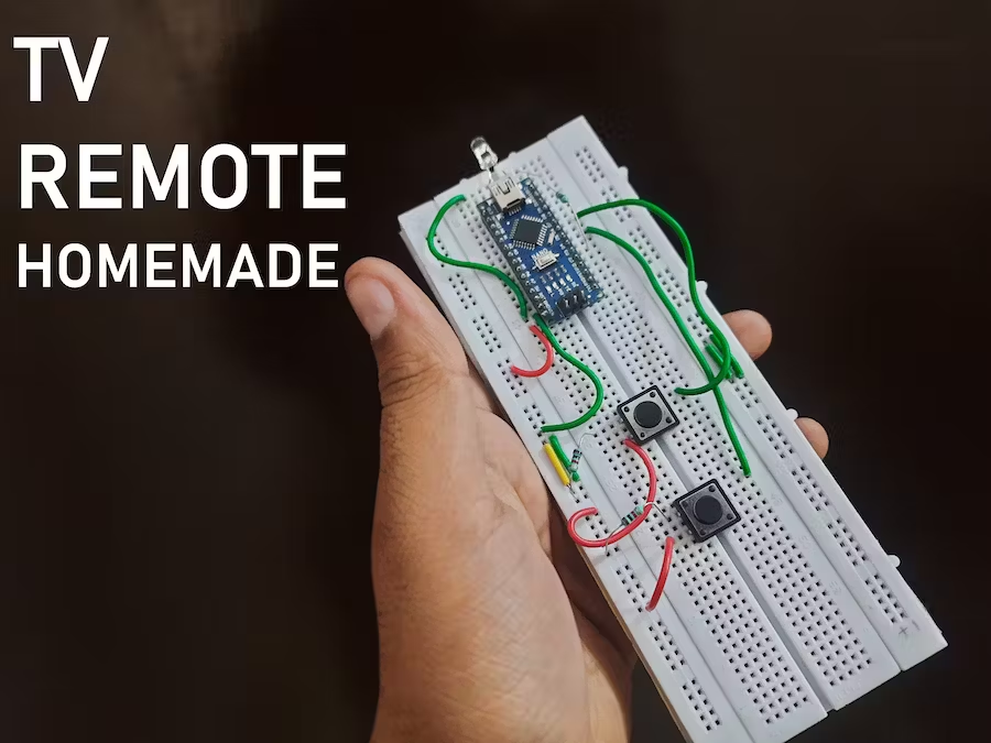
Arduino based universal TV Remote
We can control Tv or any IR system using this, Arduino made this very simple
to program and run different instructions


Things used in this project


Hardware components
- Arduino Nano R3 × 1
- IR transmitter (generic) × 1
- Tactile Switch, Top Actuated × 1
Software apps and online services
- EasyEDA
- JLCPCB EasyEDA
- Arduino IDE
Hand tools and fabrication machines
Soldering iron (generic)
Solder Wire, Lead Free
Breadboard, 400 Pin
Story
Hello guys, today in this tutorial we will learn, how to make a Universal Tv
(IR) Remote. Though this we can control appliances that have IR receiver.
Any of IR remote control device can be controlled using this. Suppose you
have a Tv, if someone is watching and you don’t have control over remote.
But you want to change channel in this condition you can use this remote.
This condition is quite popular in Indian homes in our time. Or you can just
learn, how to make your own one Universal all in one remote control. In last
we will make a working pcb and order it from our sponsor JLCPCB.
JLCPCB is China’s No.1 pcb manufacturer and provide 2-layer pcb in just
$2.
Features:
- Made using Arduino (programmable).
- Can be used with any appliances (TV/ Ac/ home theater/ radio/ Home automation).
- Have 11 buttons for different actions to be performed.
- Small size
- Rechargeable
- DIY project
Working concept:
To make a universal remote, first we should know some important concepts of
Infrared remote and receiver. let's understand this with a simple example.
Example:
To change a channel in Tv, IR remote will transmit a code and this code is
received by TV then decoded by TV’s microcontroller and processed /
channel got changed. So, to make our one we have to first know the code that
is transmitted by remote. This process is called decoding, we have to make
our own remote decoding system. Then we write down all the decoded values of
buttons like, CH+, CH-, VOL+, VOL-, POWER, Settings.
We will feed these values in our Arduino control universal remote and
complete this project.
See these tutorials first:
- How to decode IR Remote using Arduino.
- How to make a remote-control electric board.
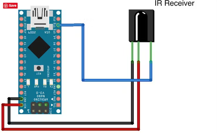 Before going deep in this lecture, please complete these 2 tutorials so that
terms like- (Decoding, IR receiver and transmitting, etc.) be more cleared
to you.
Before going deep in this lecture, please complete these 2 tutorials so that
terms like- (Decoding, IR receiver and transmitting, etc.) be more cleared
to you.
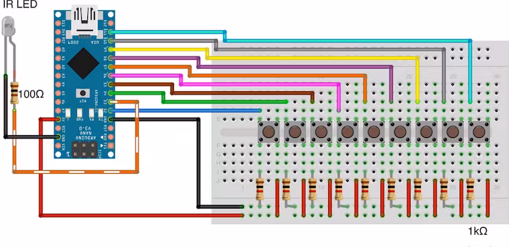
Breadboard Circuit diagram:
Components used:
- Arduino
- IR led
- Tactile buttons
- 1k resistor x11
- 220 ohms resistor
- PCB and wires
- Battery (3.7v)
Circuit diagram:
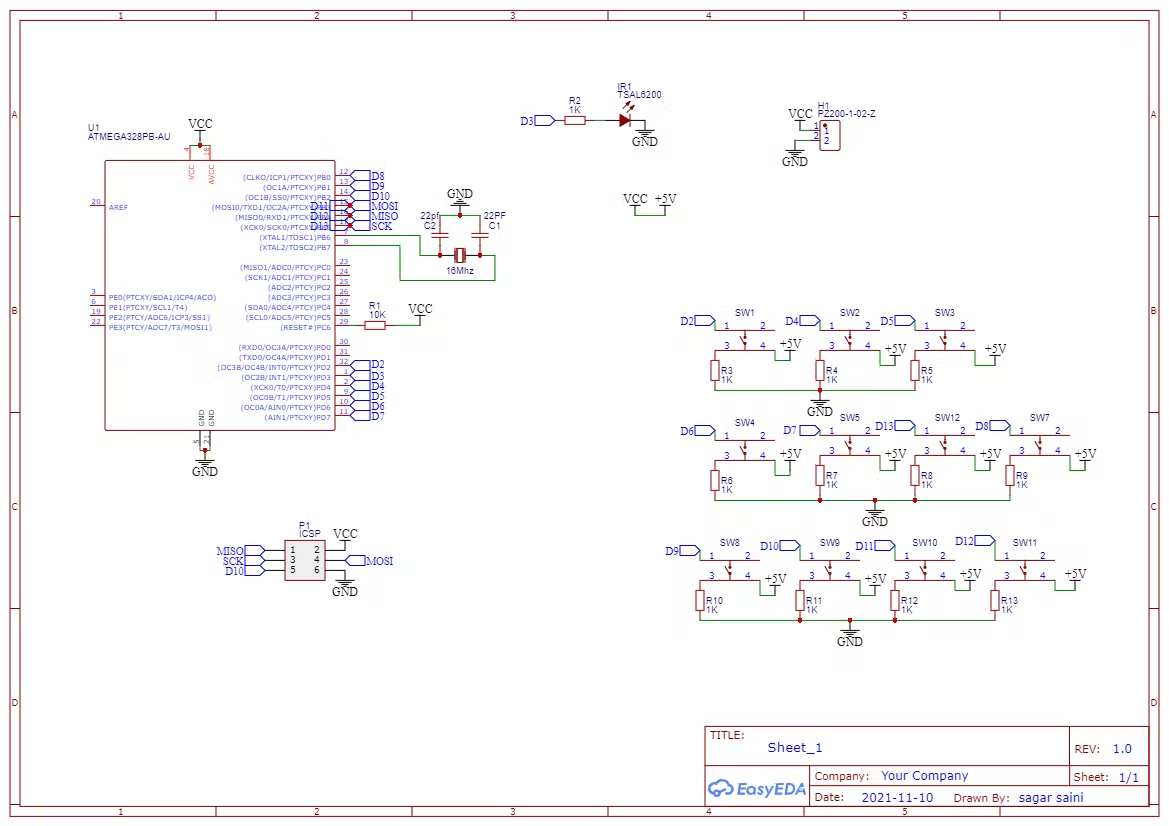
Circuit explanation:
Making this circuit with Arduino is very simple, but if you are using
Arduino’s Atmega328p chip then, you have to make general connection for
clock and reset as shown in circuit diagram. Also, the ICSP (programming
serial pins) are given in the schematics to upload the sketch/ change the
control signals.
IR led positive terminal is connected with D3(digital pin 3) using 1k/220
ohms resistor and negative terminal is grounded. 11 Tactile switch buttons
are used in this project for 11 different instructions to be processed. Each
one is connected to different digital pins from D2 to D13. One terminal of
each is connected with ground with 1k resistor. 2 pin headers is to supply
power to the circuit and Arduino.
Code:
/*H*******************************************************
* sagar saini : hackster saini_sagar_7294 follow us on instagram, hackaday
profile link:https://hackaday.io/project/182316-arduino-based-ir-remote-decoder
Universal IR Remote Controller
*********************************************************/
#include <IRremote.h>
#include "LowPower.h"
// **************** DEFINES ****************************
const int b1 = 2;
const int b2 = 4;
const int b3 = 5;
const int b4 = 6;
const int b5 = 7;
const int b6 = 8;
const int b7 = 9;
const int b8 = 10;
const int b9 = 11;
const int b10 = 12;
// **************** PROTOTYPES *************************
void wakeUp();
// **************** VARIABLES **************************
IRsend irsend;
int timer;
int modeCounter = 0;
/*F*******************************************************
*
*********************************************************/
void
setup()
{
pinMode( b1, INPUT);
pinMode( b2, INPUT);
pinMode( b3, INPUT);
pinMode( b4, INPUT);
pinMode( b5, INPUT);
pinMode( b6, INPUT);
pinMode( b7, INPUT);
pinMode( b8, INPUT);
pinMode( b9, INPUT);
pinMode( b10, INPUT);
}
/*F*******************************************************
*
*********************************************************/
void
loop()
{
attachInterrupt( 0, wakeUp, HIGH );
while( timer < 10000)
{
if( digitalRead( b1 ) == HIGH )
{
timer = 0;
delay( 50 );
irsend.sendNEC( 0x0000, 32 ); // Enter Remote Hex Value
}
if( digitalRead( b2 ) == HIGH )
{
timer = 0;
delay( 50 );
irsend.sendNEC( 0x0000, 32 ); // Enter Remote Hex Value
}
if( digitalRead( b3 ) == HIGH)
{
timer = 0;
delay( 50 );
irsend.sendNEC( 0x0000, 32 ); // Enter Remote Hex Value
}
if( digitalRead( b4 ) == HIGH)
{
timer = 0;
delay( 50 );
irsend.sendNEC( 0x0000, 32 ); // Enter Remote Hex Value
}
if( digitalRead( b5 ) == HIGH)
{
timer = 0;
delay( 50 );
irsend.sendNEC( 0x0000, 32); // Enter Remote Hex Value
}
if( digitalRead( b6 ) == HIGH)
{
timer = 0;
delay( 50 );
irsend.sendNEC( 0x0000, 32); // Enter Remote Hex Value
}
if( digitalRead( b7 ) == HIGH)
{
timer = 0;
delay( 50 );
irsend.sendNEC( 0x0000, 32); // Enter Remote Hex Value
}
if( digitalRead(b8) == HIGH)
{
timer = 0;
delay( 50 );
irsend.sendNEC( 0x0000, 32); // Enter Remote Hex Value
}
if( digitalRead(b9) == HIGH)
{
timer = 0;
delay( 50 );
irsend.sendNEC( 0x0000, 32); // Enter Remote Hex Value
}
if( digitalRead(b10) == HIGH)
{
timer = 0;
delay( 50 );
irsend.sendNEC( 0x0000, 32); // Enter Remote Hex Value
}
delay( 1 );
timer = timer + 1;
}
LowPower.powerDown( SLEEP_FOREVER, ADC_OFF, BOD_OFF);
}
/*F*******************************************************
*
*********************************************************/
void
wakeUp()
{
timer = 0;
}
In this code low power library is used to increase the battery life, in this
way a single battery withstand up to 3-4 months after a single charge. All the
library files are given below.
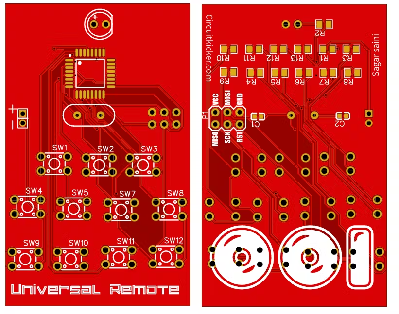
About JLCPCB:
JLCPCB is the one of the most popular PCB makers. Price is just $2 for 2, 4 and 6 layer PCB. They just launched new purple solder mask, aluminum Pcb and 3d printing service in very low cost. Pcb quality is not compromised at any cost. Check them out right now from Here.https://jlcpcb.com/IAT
Sign up using this link and get $30 worth PCB coupon free, Order PCB and enjoy the service of JLCPCB.