methods
- Using a Resistor to Determine Inductance
- Measuring with an LCR Meter
- Calculating Inductance on a Voltage-Current Slope
Method 1
Using a Resistor to Determine Inductance
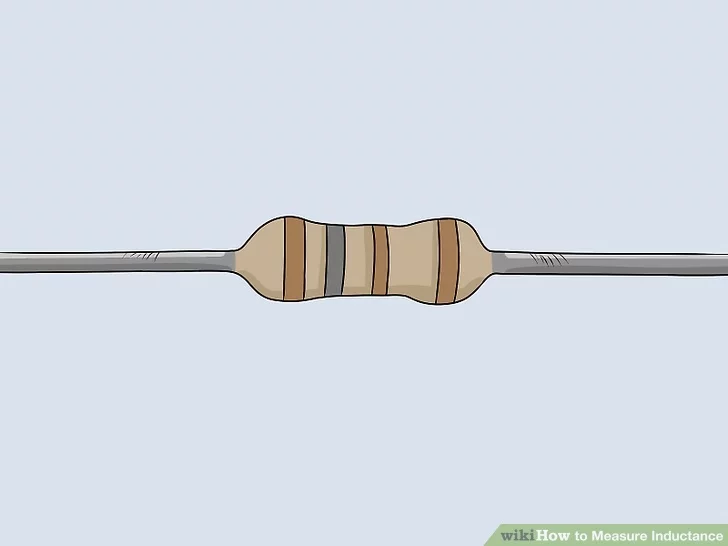 Image titled Measure Inductance Step 1
 - Choose a 100-ohm resistor with 1% tolerance. Resistors have colored bands
that can help you tell them apart. A 100-ohm resistor will have a brown,
black, and brown band. The final band at the far end will also be brown to
represent 1% resistance. If you have a bunch of resistors to choose from,
pick one with a known resistance value.[1]
Resistors are labeled when they are new, but they can be easy to
mistake once they are out of the packaging. Always test inductance using a
resistor you are familiar with to ensure you get an accurate result.
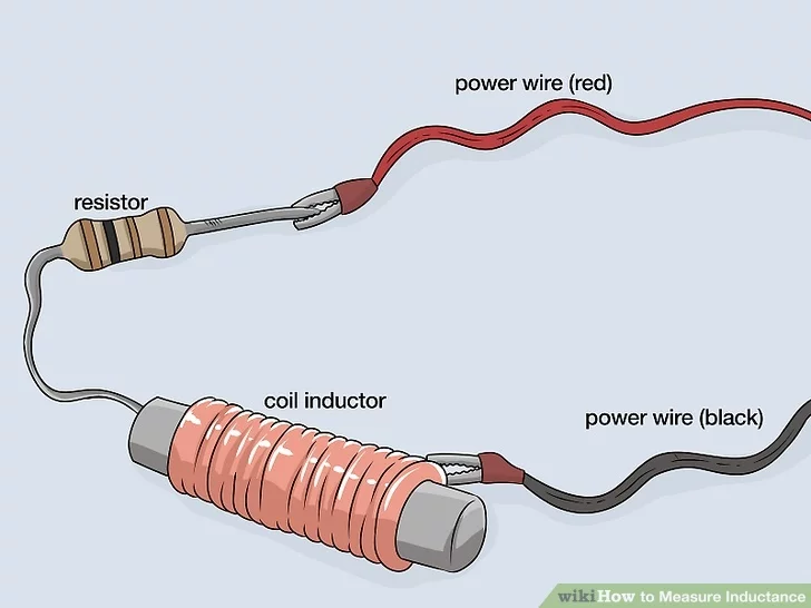 Image titled Measure Inductance Step 2
-
Connect the inductor coil in series with the resistor. In series means
the current passes through the coil one after the other. Start setting up a
circuit by placing the coil and resistor next to each other. Make sure they
have 1 terminal touching. To finish the circuit, you will also need to touch
power wires to the exposed ends of the resistor and inductor.[2]
- Purchase power wires online or at a hardware store. They will usually be red and black so you can easily tell them apart. Touch the red wire to the exposed end of the resistor and the black wire to the opposite end of the inductor.
- If you don’t already have one, consider getting a breadboard. The holes in the board help a lot with connecting the wires and components.
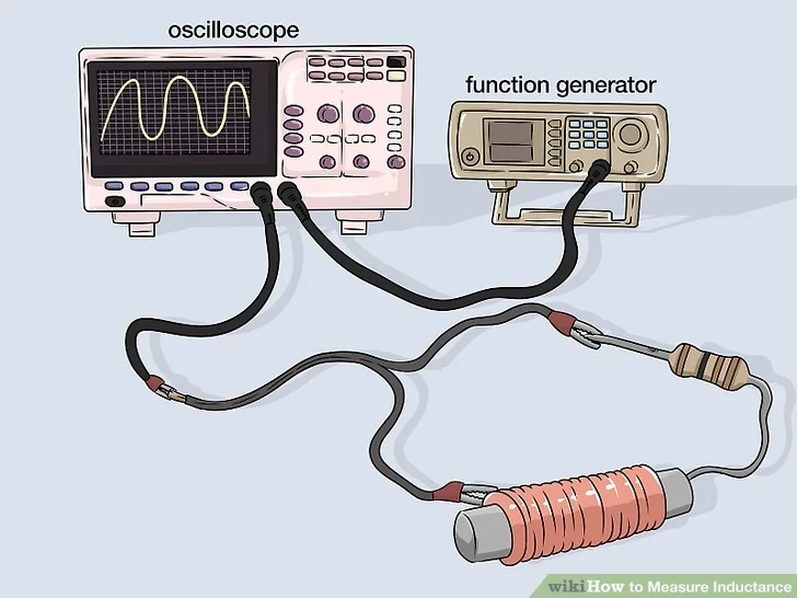 Image titled Measure Inductance Step 3
-
Wire a function generator and an oscilloscope into the circuit. Take the
output leads from the function generator and plug them into the
oscilloscope. Then, turn on both devices to make sure they are working. Once
they are both on, take the function generator’s red output lead and
connect it to the red power wire in your circuit. Connect the
oscilloscope’s black input lead to the black wire in your circuit.[3]
- A function generator is a piece of electrical testing equipment that sends electrical waves through the circuit. It allows you to control the signal moving through the coil so you can accurately calculate the inductance.
- The oscilloscope is used to detect and display the signal voltage running through the circuit. You need it to visualize the signal you’re setting up with the function generator.
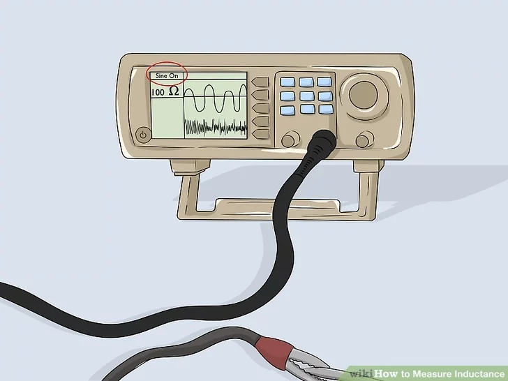 Image titled Measure Inductance Step 4
-
Run a current through the circuit with the function generator. The
function generator simulates currents the inductor and resistor would
receive if they were actually being used. Use the control knob on the device
to start the current. Try setting the function generator to something like
100 or 50 ohms. Make sure the generator is set to sine waves so you see big,
curving waves flowing steadily across the screen.[4]
- Access the generator’s settings to change the wave type. Function generators can make square waves, triangular waves, and other varieties that aren’t useful for calculating inductance.
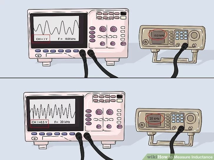 Image titled Measure Inductance Step 5
- Monitor the input voltage and resistor voltage on the screen. Look to
the oscilloscope screen for a pair of sine waves. One will be controllable
through the function generator. The other, smaller wave comes from where the
inductor and resistor meet. Adjust the function generator’s frequency so
the junction voltage listed on the screen is half of the original input
voltage.[5]
- For example, set the generator frequency so the voltage between the peaks of both waves is listed as 1 V, which you will see on the oscilloscope. Then, change it until the voltage is 0.5 V.
- The junction voltage is the difference between the sine waves on the oscilloscope. You need it to be half of the signal generator’s original voltage.
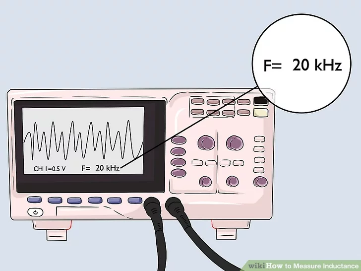 Image titled Measure Inductance Step 6
- Find the frequency of the functional generator current. This will be
displayed on the oscilloscope. Check the numbers on the bottom of the
readout to find one in kilohertz, or kHz. Note this number, since you will
need to use it in a calculation to find the inductance.[6]
- If you need to convert hertz (Hz) to kilohertz, remember that: 1 kHz = 1,000 Hz. For instance, 1 Hz / (1,000 Hz/kHz) = 0.001 kHz.
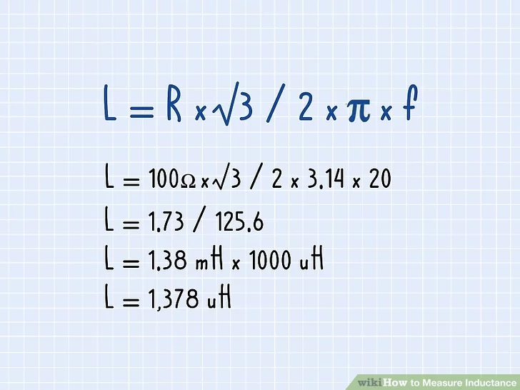 Image titled Measure Inductance Step 7
- Calculate the inductance using a mathematical formula. Use the formula
L = R * sqrt(3) / (2 * pi * f).
L is the inductance, so you need the resistance (R) and the frequency (f) you
figured out earlier. Another option is to type your measurements into an
inductance calculator, such as at:
https://daycounter.com/Articles/How-To-Measure-Inductance.phtml.[7]
- Start by multiplying the resistance of the resistor by the square root of 3. For instance, 100 ohms x 1.73 = 173. (R * √3)
- Next, multiply 2, pi, and the frequency. For example, if the resistance was 20 kHz: 2 * 3.14 * 20 = 125.6. (2λ * π * 20)
- Finish by dividing the first number by the second number. In this case, 173 / 125.6 = 1.38 millihenries (mH).
- To convert millihenries into microhenries (uH), multiply by 1,000: 1.38
x 1,000 = 1378 uH.
Method 2: Measuring with an LCR Meter
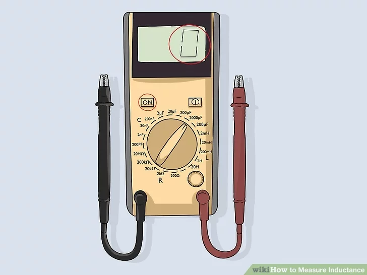 Image titled Measure Inductance Step 8
- Power the LCR meter and wait for it to turn on. A basic LCR meter is
very similar to a multimeter normally used to measure things like voltage
and current. Most meters are handheld with a readout screen that will
display 0 after you press the power button. If it doesn’t display 0, press
the reset button to set the meter at 0.[8]
- There are also larger electronic machines that make the testing process even easier than normal. They often have room for you to plug in the inductor coil for a more accurate result.
- Multimeters cannot be used to measure inductance. They don’t have the ability, but fortunately, inexpensive handheld LCR meters are available online.
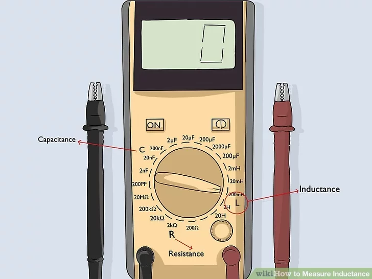 Image titled Measure Inductance Step 9
- Set the LCR to measure L, or inductance. An LCR meter can take several
measurements, which will be listed on the dial. L means inductance, so it is
the one you need. For handheld meters, turn the dial to point to the L. If
you’re using an electronic device, press the buttons on the screen to set
the machine to L.[9]
- LCR meters have multiple settings, so make sure you’re using the correct one. The C setting is for capacitance and the R is for resistance.
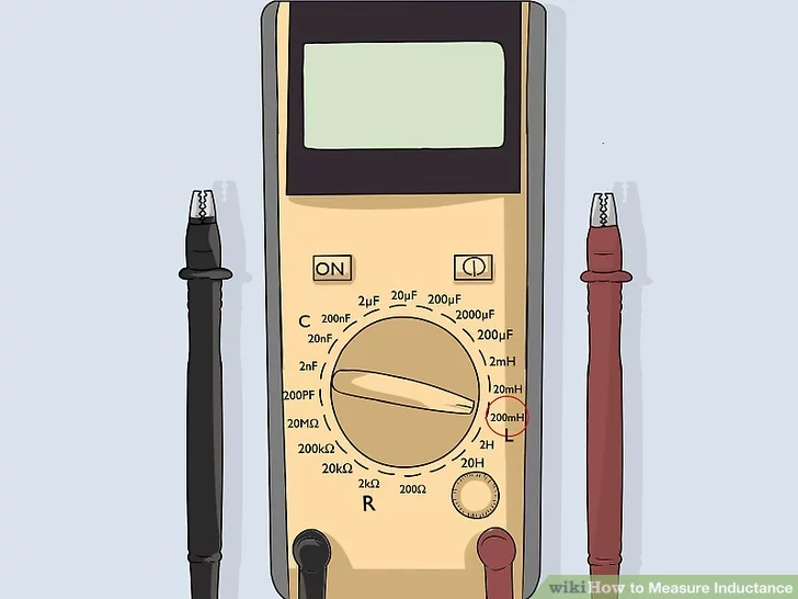 Image titled Measure Inductance Step 10
- Set the meter to 100 kHz at 1 volt. LCR meters generally offer several
different test settings. The lowest inductance test is usually something
like 200 uH. If you’re setting a tabletop meter, 100 kHz at 1 volt is
perfect for most devices.[10]
-
Using the wrong setting makes the test more inaccurate. Most LCR
meters are meant to test at a low current, but you should still avoid making
the current stronger than what the inductor coil can handle.
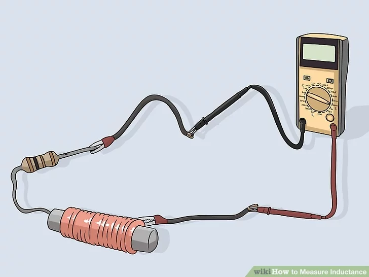 Image titled Measure Inductance Step 11
- Connect the leads to the LCR meter. The meter will have a black and red
lead just like a multimeter. The red lead fits in the plug marked as
positive, while the black one fits in the plug marked as negative. Touch the
leads to the terminal ends of the device you are testing to begin sending a
current through it.[11]
-
Some LCR meters have a slot where you can plug in testing objects
like capacitors and coils. Fit the device’s terminals into the sockets to
test it.
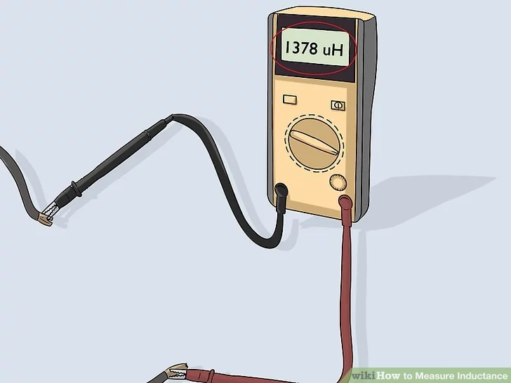 Image titled Measure Inductance Step 12
- Check the display screen to figure out the inductance. LCR devices perform inductance tests almost instantaneously. You should notice the readout on the screen change right away. It will show you a number in microhenries (uH). Once you have the number, you can shut off the meter and remove the device.
Method 3
Calculating Inductance on a Voltage-Current Slope
- Connect the inductor coil to a pulsed voltage source. The easiest way to
get a pulsed current is by purchasing a pulse generator. It works similar to
a regular function generator and hooks up to a circuit the same way. Hook
the output lead from the generator to a red power wire you will need to
connect to a sense resistor.[12]
- Another way to get a pulse is by building the circuit to make your own. It can damage nearby electronics, so be careful when using it.
- Pulse generators give you more control over the current than a custom-built circuit, so rely on a generator if you have one available.
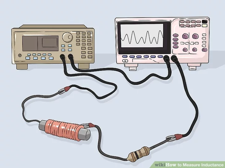 Image titled Measure Inductance Step 14
- Set up the current monitors with a sense resistor and oscilloscope. You
will need a current sense resistor to put into the circuit. Set it behind
the inductor, making sure the terminals touch before connecting a red power
wire to the opposite end. Add the oscilloscope next by connecting its black
input lead to a black power wire attached to the end of the inductor.[13]
- Test the monitors after wiring everything into place. If everything works, you will see movement on the oscillator screen when the pulsed current activates.
- A current sense resistor is a special kind of resistor that takes up a minimal amount of power. It’s also called a shunt resistor and it’s necessary for getting an accurate voltage reading.
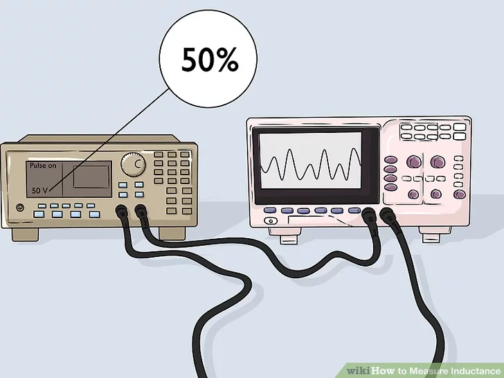
- Set the cycle of the pulse to 50% or less. Watch the pulse as it moves
across the oscilloscope screen. The high points of the wave indicate when
the pulse is active. Those high points need to be about the same length as
the low points. The pulse cycle is the length of one complete wave on the
oscilloscope.[14]
- For example, the pulse could be active 1 second, then off 1 second. The wave pattern on the display would look very consistent since the pulse is only active for half the time.
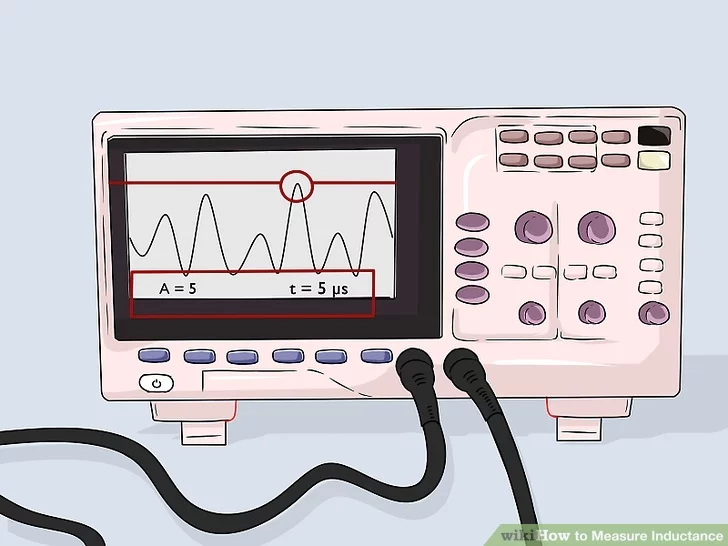
- Read the peak current and the amount of time between voltage pulses.
Check the oscilloscope for these measurements. The peak current is the crest
of the tallest wave you see on the screen and will be measured in amperes.
The time between these crests will be shown in microseconds. Once you have
both measurements, you can calculate the inductance.[15]
- There are 1,000,000 microseconds in a second. If you need to convert to seconds, divide the microseconds by 1,000,000.
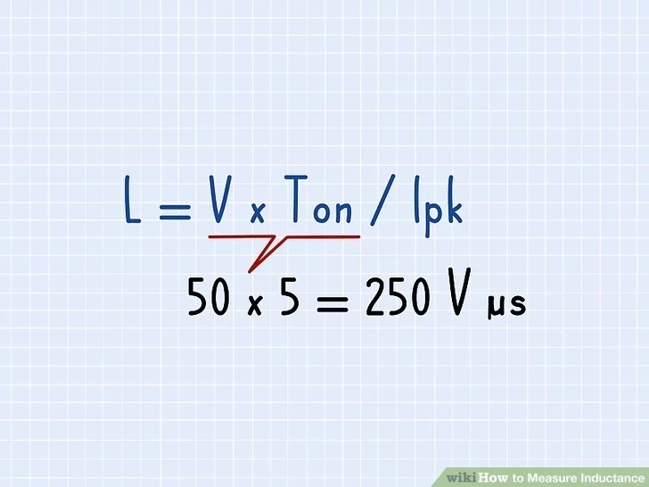 Image titled Measure Inductance Step 17
- Multiply the voltage and the length of the pulses. Use the formula L =
V*Ton/Ipk to calculate the inductance. All of the numbers needed should be
right there on the oscilloscope. V stands for the voltage delivered by the
pulses, Ton stands for the time between each pulse, and lpk means the peak
current you measured earlier.[16]
For example, if a pulse of 50 volts is delivered every 5
microseconds: 50 x 5 = 250 volt-microseconds.
Another option is to type the numbers into a calculator, such as the
one at https://daycounter.com/Articles/How-To-Measure-Inductance.phtml.
Image titled Measure Inductance Step 18
6
Divide the product by the peak current to get the inductance. Refer to
the oscilloscope readout to determine the peak current. Plug it into the
formula to successfully finish the calculation!
For example, 250 volt-microseconds / 5 amperes = 50 microhenries
(mH).
Although the math seems pretty simple, setting up the measurement is
more complex than other methods. Once you have everything working, figuring
out the inductance is a snap!
Community Q&A
Question
How can method 1 be correct if Z=2*PI*f*L?
Community Answer
Community Answer
He adjusts frequency so the voltage drop due to the impedance = V drop
of resistance. This then becomes, Z = 2piFL = R so L = R/(2piF).
Not Helpful 10
Helpful 36
Question
Can I measure inductance using an LCR meter?
Community Answer
Community Answer
Of course you can; that's what an LCR meter is for. Keep in mind that
because the method for evaluating inductance and capacitance may vary from
one meter to another, the results will be different. There is no need to
spend a lot of money on a top quality one. If this is just for your hobby,
then a low end one will be just fine as you won't need the extra precision a
professional would.
Not Helpful 0
Helpful 10
Question
Where does the formula of the second method (point n4) come from?
Community Answer
Community Answer
It is based on the equation used to evaluate the gain at a given
frequency vs. the cutoff frequency. The equation is
1/(sqrt(1+(R/(2*pi*f*L))^2)). By re-arranging the terms to find L when we
have a gain of 1/2 as per the example above, you will end up with that
equation. Don't forget that there is a note below the picture indicating
that the formula isn't correct; the one below the picture, mentioned in a
warning note, is the correct
one. The picture and explanation underneath it will need to be updated to
reflect the correct information.
Not Helpful 2
Helpful 5
See more answers
Ask a Question
Submit
Video
Tips
When a group of inductors are wired in a series, their total inductance
is the sum of each inductor.
Longer coils tend to have lower inductance than shorter coils because
of
their shape.
If you wire a group of inductors parallel to one another, the total
inductance is much less than usual. You will need to divide 1 by each
inductance, add up the total, then divide 1 by that number.
Show More Tips
Warning
Quality inductance meters can be costly and uncommon. In addition,
affordable LCR meters typically measure at a low current, so they aren’t
useful for testing large inductors.
Things You'll Need
Using a Resistor to Determine Inductance Pulsed voltage generator Oscilloscope Induction coil Connecting wires Calculator Measuring with an LCR Meter LCR meter Inductor or another device Black and red leads Calculating Inductance on a Voltage Current Slope Pulsed voltage generator Oscilloscope Current sense resistor Induction coil Connecting wires Calculator You Might Also Like Calculate Wattage How to Calculate Wattage Measure Amperage How to Measure Amperage How to Test a Relay How to Interpret Your Residential Electrical Meter Read a Capacitor How to Read a Capacitor Determine Amperage of Circuit Breaker How to Determine Amperage of Circuit Breaker Test a Capacitor How to Test a Capacitor Measure Capacitance How to Measure Capacitance Calculate Kilowatt Hours How to Calculate Kilowatt Hours Test a Potentiometer How to Test a Potentiometer How to Use an Ohmmeter Test a Four Terminal Relay How to Test a Four Terminal Relay Read a Digital Ohm Meter How to Read a Digital Ohm Meter Test Voltage with a Multimeter How to Test Voltage with a Multimeter Expert Interview Thanks for reading our article! If you’d like to learn more about electrical maintenance, check out our in-depth interview with Martin Hennum. References ↑ https://meettechniek.info/passive/inductance.html ↑ https://www.testandmeasurementtips.com/how-to-measure-inductance/ ↑ https://meettechniek.info/passive/inductance.html ↑ https://www.youtube.com/watch?v=iQQe8uSZ8xc ↑ https://www.youtube.com/watch?v=iQQe8uSZ8xc ↑ https://www.allaboutcircuits.com/textbook/alternating-current/chpt -3/series-resistor-inductor-circuits/ ↑ https://doc.modelica.org/Modelica%203.2.3/Resour ces/helpMapleSim/Electrical/QuasiStationary/MultiPhase/Examples/index.html ↑ https://www.youtube.com/watch?v=BYjNkWE2v2E&feature=youtu.be&t=26 ↑ https://www.electronics-notes.com/articles/test-methods/lcr-meter -bridge/primer-basics.php
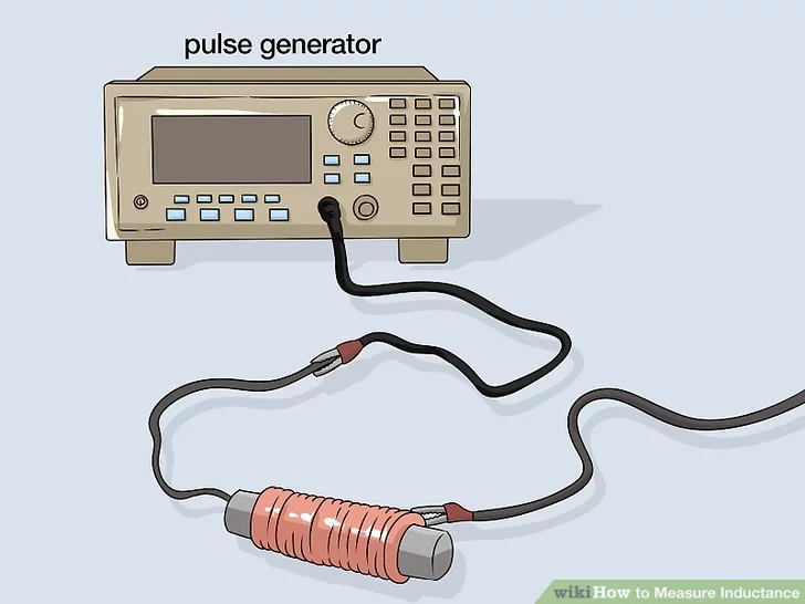 Image titled Measure Inductance Step 13