 Active Band Pass Filter
The principal characteristic of a Band Pass Filter or any filter for that
matter, is its ability to pass frequencies relatively unattenuated over a
specified band or spread of frequencies called the “Pass Band”.
For a low pass filter this pass band starts from 0Hz or DC and continues up
to the specified cut-off frequency point at -3dB down from the maximum pass
band gain. Equally, for a high pass filter the pass band starts from this
-3dB cut-off frequency and continues up to infinity or the maximum open loop
gain for an active filter.
However, the Active Band Pass Filter is slightly different in that it is a
frequency selective filter circuit used in electronic systems to separate a
signal at one particular frequency, or a range of signals that lie within a
certain “band” of frequencies from signals at all other frequencies.
This band or range of frequencies is set between two cut-off or corner
frequency points labelled the “lower frequency” ( ƒL ) and the
“higher frequency” ( ƒH ) while attenuating any signals outside of
these two points.
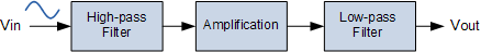
Simple Active Band Pass Filter can be easily made by cascading together a
single Low Pass Filter with a single High Pass Filter as shown.
Active Band Pass Filter
The principal characteristic of a Band Pass Filter or any filter for that
matter, is its ability to pass frequencies relatively unattenuated over a
specified band or spread of frequencies called the “Pass Band”.
For a low pass filter this pass band starts from 0Hz or DC and continues up
to the specified cut-off frequency point at -3dB down from the maximum pass
band gain. Equally, for a high pass filter the pass band starts from this
-3dB cut-off frequency and continues up to infinity or the maximum open loop
gain for an active filter.
However, the Active Band Pass Filter is slightly different in that it is a
frequency selective filter circuit used in electronic systems to separate a
signal at one particular frequency, or a range of signals that lie within a
certain “band” of frequencies from signals at all other frequencies.
This band or range of frequencies is set between two cut-off or corner
frequency points labelled the “lower frequency” ( ƒL ) and the
“higher frequency” ( ƒH ) while attenuating any signals outside of
these two points.
Simple Active Band Pass Filter can be easily made by cascading together a
single Low Pass Filter with a single High Pass Filter as shown.
 band pass filter design
The cut-off or corner frequency of the low pass filter (LPF) is higher than
the cut-off frequency of the high pass filter (HPF) and the difference
between the frequencies at the -3dB point will determine the “bandwidth”
of the band pass filter while attenuating any signals outside of these
points. One way of making a very simple Active Band Pass Filter is to
connect the basic passive high and low pass filters we look at previously to
an amplifying op-amp circuit as shown.
band pass filter design
The cut-off or corner frequency of the low pass filter (LPF) is higher than
the cut-off frequency of the high pass filter (HPF) and the difference
between the frequencies at the -3dB point will determine the “bandwidth”
of the band pass filter while attenuating any signals outside of these
points. One way of making a very simple Active Band Pass Filter is to
connect the basic passive high and low pass filters we look at previously to
an amplifying op-amp circuit as shown.
Active Band Pass Filter Circuit
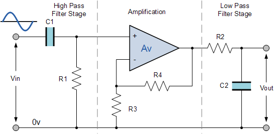 active band pass filter
This cascading together of the individual low and high pass passive filters
produces a low “Q-factor” type filter circuit which has a wide pass
band. The first stage of the filter will be the high pass stage that uses
the capacitor to block any DC biasing from the source.
This design has the advantage of producing a relatively flat asymmetrical
pass band frequency response with one half representing the low pass
response and the other half representing high pass response as shown.
active band pass filter
This cascading together of the individual low and high pass passive filters
produces a low “Q-factor” type filter circuit which has a wide pass
band. The first stage of the filter will be the high pass stage that uses
the capacitor to block any DC biasing from the source.
This design has the advantage of producing a relatively flat asymmetrical
pass band frequency response with one half representing the low pass
response and the other half representing high pass response as shown.
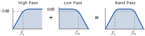 cascading of filters
The higher corner point ( ƒH ) as well as the lower corner frequency cut-off
point ( ƒL ) are calculated the same as before in the standard first-order
low and high pass filter circuits.
Obviously, a reasonable separation is required between the two cut-off
points to prevent any interaction between the low pass and high pass stages.
The amplifier also provides isolation between the two stages and defines the
overall voltage gain of the circuit.
The bandwidth of the filter is therefore the difference between these upper
and lower -3dB points. For example, suppose we have a band pass filter whose
-3dB cut-off points are set at 200Hz and 600Hz. Then the bandwidth of the
filter would be given as: Bandwidth (BW) = 600 – 200 = 400Hz.
The normalised frequency response and phase shift for an active band pass
filter will be as follows.
cascading of filters
The higher corner point ( ƒH ) as well as the lower corner frequency cut-off
point ( ƒL ) are calculated the same as before in the standard first-order
low and high pass filter circuits.
Obviously, a reasonable separation is required between the two cut-off
points to prevent any interaction between the low pass and high pass stages.
The amplifier also provides isolation between the two stages and defines the
overall voltage gain of the circuit.
The bandwidth of the filter is therefore the difference between these upper
and lower -3dB points. For example, suppose we have a band pass filter whose
-3dB cut-off points are set at 200Hz and 600Hz. Then the bandwidth of the
filter would be given as: Bandwidth (BW) = 600 – 200 = 400Hz.
The normalised frequency response and phase shift for an active band pass
filter will be as follows.
Active Band Pass Frequency Response
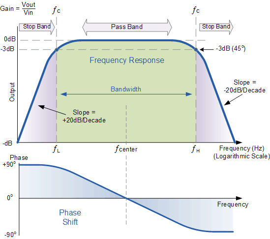 active band pass filter frequency response
While the above passive tuned filter circuit will work as a band pass
filter, the pass band (bandwidth) can be quite wide and this may be a
problem if we want to isolate a small band of frequencies. Active band pass
filter can also be made using inverting operational amplifier.
So by rearranging the positions of the resistors and capacitors within the
filter we can produce a much better filter circuit as shown below. For an
active band pass filter, the lower cut-off -3dB point is given by ƒC1 while
the upper cut-off -3dB point is given by ƒC2.
active band pass filter frequency response
While the above passive tuned filter circuit will work as a band pass
filter, the pass band (bandwidth) can be quite wide and this may be a
problem if we want to isolate a small band of frequencies. Active band pass
filter can also be made using inverting operational amplifier.
So by rearranging the positions of the resistors and capacitors within the
filter we can produce a much better filter circuit as shown below. For an
active band pass filter, the lower cut-off -3dB point is given by ƒC1 while
the upper cut-off -3dB point is given by ƒC2.
Inverting Band Pass Filter Circuit
 inverting amplifier band pass filter
 active filter cut-off frequency
This type of band pass filter is designed to have a much narrower pass band.
The centre frequency and bandwidth of the filter is related to the values of
R1, R2, C1 and C2. The output of the filter is again taken from the output
of the op-amp.
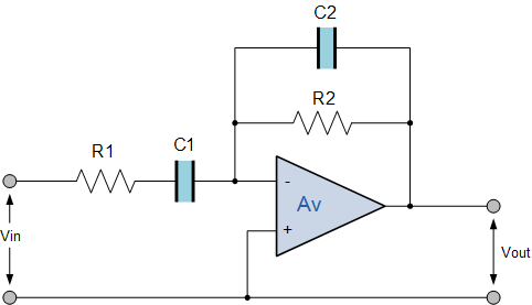
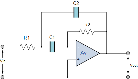
Multiple Feedback Band Pass Active Filter
We can improve the band pass response of the above circuit by rearranging
the components again to produce an infinite-gain multiple-feedback (IGMF)
band pass filter. This type of active band pass design produces a
“tuned” circuit based around a negative feedback active filter giving it
a high “Q-factor” (up to 25) amplitude response and steep roll-off on
either side of its centre frequency. Because the frequency response of the
circuit is similar to a resonance circuit, this center frequency is referred
to as the resonant frequency, ( ƒr ). Consider the circuit below.
active filter cut-off frequency
This type of band pass filter is designed to have a much narrower pass band.
The centre frequency and bandwidth of the filter is related to the values of
R1, R2, C1 and C2. The output of the filter is again taken from the output
of the op-amp.
Multiple Feedback Band Pass Active Filter
We can improve the band pass response of the above circuit by rearranging
the components again to produce an infinite-gain multiple-feedback (IGMF)
band pass filter. This type of active band pass design produces a
“tuned” circuit based around a negative feedback active filter giving it
a high “Q-factor” (up to 25) amplitude response and steep roll-off on
either side of its centre frequency. Because the frequency response of the
circuit is similar to a resonance circuit, this center frequency is referred
to as the resonant frequency, ( ƒr ). Consider the circuit below.
Infinite Gain Multiple Feedback Active Filter
 infinite gain multiple feedback active filter
This active band pass filter circuit uses the full gain of the operational
amplifier, with multiple negative feedback applied via resistor, R2 and
capacitor C2. Then we can define the characteristics of the IGMF filter as
follows:
infinite gain multiple feedback active filter
This active band pass filter circuit uses the full gain of the operational
amplifier, with multiple negative feedback applied via resistor, R2 and
capacitor C2. Then we can define the characteristics of the IGMF filter as
follows:
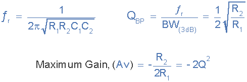 igmf filter characteristics
We can see then that the relationship between resistors, R1 and R2
determines the band pass “Q-factor” and the frequency at which the
maximum amplitude occurs, the gain of the circuit will be equal to -2Q2.
Then as the gain increases so to does the selectivity. In other words, high
gain – high selectivity.
igmf filter characteristics
We can see then that the relationship between resistors, R1 and R2
determines the band pass “Q-factor” and the frequency at which the
maximum amplitude occurs, the gain of the circuit will be equal to -2Q2.
Then as the gain increases so to does the selectivity. In other words, high
gain – high selectivity.
Active Band Pass Filter Example No1 An active band pass filter that has a voltage gain Av of one (1) and a resonant frequency, ƒr of 1kHz is constructed using an infinite gain multiple feedback filter circuit. Calculate the values of the components required to implement the circuit. Firstly, we can determine the values of the two resistors, R1 and R2 required for the active filter using the gain of the circuit to find Q as follows.
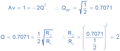 value of Q
Then we can see that a value of Q = 0.7071 gives a relationship of resistor,
R2 being twice the value of resistor R1. Then we can choose any suitable
value of resistances to give the required ratio of two. Then resistor R1 =
10kΩ and R2 = 20kΩ.
The center or resonant frequency is given as 1kHz. Using the new resistor
values obtained, we can determine the value of the capacitors required
assuming that C = C1 = C2.
value of Q
Then we can see that a value of Q = 0.7071 gives a relationship of resistor,
R2 being twice the value of resistor R1. Then we can choose any suitable
value of resistances to give the required ratio of two. Then resistor R1 =
10kΩ and R2 = 20kΩ.
The center or resonant frequency is given as 1kHz. Using the new resistor
values obtained, we can determine the value of the capacitors required
assuming that C = C1 = C2.
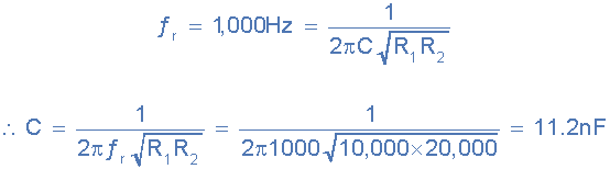 capacitor value
The closest standard value is 10nF.
capacitor value
The closest standard value is 10nF.
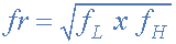
Resonant Frequency Point The actual shape of the frequency response curve for any passive or active band pass filter will depend upon the characteristics of the filter circuit with the curve above being defined as an “ideal” band pass response. An active band pass filter is a 2nd Order type filter because it has “two” reactive components (two capacitors) within its circuit design. As a result of these two reactive components, the filter will have a peak response or Resonant Frequency ( ƒr ) at its “center frequency”, ƒc. The center frequency is generally calculated as being the geometric mean of the two -3dB frequencies between the upper and the lower cut-off points with the resonant frequency (point of oscillation) being given as:
 resonant frequency
Where:
ƒr is the resonant or Center Frequency
ƒL is the lower -3dB cut-off frequency point
ƒH is the upper -3db cut-off frequency point
and in our simple example in the text above of a filters lower and upper
-3dB cut-off points being at 200Hz and 600Hz respectively, then the resonant
center frequency of the active band pass filter would be:
resonant frequency
Where:
ƒr is the resonant or Center Frequency
ƒL is the lower -3dB cut-off frequency point
ƒH is the upper -3db cut-off frequency point
and in our simple example in the text above of a filters lower and upper
-3dB cut-off points being at 200Hz and 600Hz respectively, then the resonant
center frequency of the active band pass filter would be:
 Resonant Frequency example
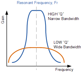
The “Q” or Quality Factor In a Band Pass Filter circuit, the overall width of the actual pass band between the upper and lower -3dB corner points of the filter determines the Quality Factor or Q-point of the circuit. This Q Factor is a measure of how “Selective” or “Un-selective” the band pass filter is towards a given spread of frequencies. The lower the value of the Q factor the wider is the bandwidth of the filter and consequently the higher the Q factor the narrower and more “selective” is the filter. The Quality Factor, Q of the filter is sometimes given the Greek symbol of Alpha, ( α ) and is known as the alpha-peak frequency where:
 quality factor alpha symbol
As the quality factor of an active band pass filter (Second-order System)
relates to the “sharpness” of the filters response around its centre
resonant frequency ( ƒr ) it can also be thought of as the “Damping
Factor” or “Damping Coefficient” because the more damping the filter
has the flatter is its response and likewise, the less damping the filter
has the sharper is its response.
The damping ratio is given the Greek symbol of Xi, ( ξ ) where:
quality factor alpha symbol
As the quality factor of an active band pass filter (Second-order System)
relates to the “sharpness” of the filters response around its centre
resonant frequency ( ƒr ) it can also be thought of as the “Damping
Factor” or “Damping Coefficient” because the more damping the filter
has the flatter is its response and likewise, the less damping the filter
has the sharper is its response.
The damping ratio is given the Greek symbol of Xi, ( ξ ) where:
 filters damping factor
The “Q” of a band pass filter is the ratio of the Resonant Frequency, (
ƒr ) to the Bandwidth, ( BW ) between the upper and lower -3dB frequencies
and is given as:
filters damping factor
The “Q” of a band pass filter is the ratio of the Resonant Frequency, (
ƒr ) to the Bandwidth, ( BW ) between the upper and lower -3dB frequencies
and is given as:
 filters quality factor quality factor equation
So for our simple example above, if the bandwidth (BW) is 400Hz, that is ƒH
– ƒL, and the center resonant frequency, ƒr is 346Hz. Then the quality
factor “Q” of the band pass filter will be given as:
346Hz / 400Hz = 0.865. Note that Q is a ratio, it has no units.
When analysing active filters, generally a normalised circuit is considered
which produces an “ideal” frequency response having a rectangular shape,
and a transition between the pass band and the stop band that has an abrupt
or very steep roll-off slope. However, these ideal responses are not
possible in the real world so we use approximations to give us the best
frequency response possible for the type of filter we are trying to design.
Probably the best known filter approximation for doing this is the
Butterworth or maximally-flat response filter. In the next tutorial we will
look at higher order filters and use Butterworth approximations to produce
filters that have a frequency response which is as flat as mathematically
possible in the pass band and a smooth transition or roll-off rate.
previousPrevious
Active High Pass Filter
Next
Second Order Filters
next
Read more Tutorials inFilters
filters quality factor quality factor equation
So for our simple example above, if the bandwidth (BW) is 400Hz, that is ƒH
– ƒL, and the center resonant frequency, ƒr is 346Hz. Then the quality
factor “Q” of the band pass filter will be given as:
346Hz / 400Hz = 0.865. Note that Q is a ratio, it has no units.
When analysing active filters, generally a normalised circuit is considered
which produces an “ideal” frequency response having a rectangular shape,
and a transition between the pass band and the stop band that has an abrupt
or very steep roll-off slope. However, these ideal responses are not
possible in the real world so we use approximations to give us the best
frequency response possible for the type of filter we are trying to design.
Probably the best known filter approximation for doing this is the
Butterworth or maximally-flat response filter. In the next tutorial we will
look at higher order filters and use Butterworth approximations to produce
filters that have a frequency response which is as flat as mathematically
possible in the pass band and a smooth transition or roll-off rate.
previousPrevious
Active High Pass Filter
Next
Second Order Filters
next
Read more Tutorials inFilters