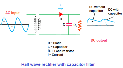
 When AC voltage is applied, during the positive half cycle, the diode D is
forward biased and allows electric current through it.
As we already know that, the capacitor provides high resistive path to dc
components (low-frequency signal) and low resistive path to ac components
(high-frequency signal).
Electric current always prefers to flow through a low resistance path. So
when the electric current reaches the filter, the dc components experience a
high resistance from the capacitor and ac components experience a low
resistance from the capacitor.
The DC Components does not like to flow
through the capacitor (high resistance path). So they find an
alternative path (low resistance path) and flows to the load resistor (RL)
through that path.
When AC voltage is applied, during the positive half cycle, the diode D is
forward biased and allows electric current through it.
As we already know that, the capacitor provides high resistive path to dc
components (low-frequency signal) and low resistive path to ac components
(high-frequency signal).
Electric current always prefers to flow through a low resistance path. So
when the electric current reaches the filter, the dc components experience a
high resistance from the capacitor and ac components experience a low
resistance from the capacitor.
The DC Components does not like to flow
through the capacitor (high resistance path). So they find an
alternative path (low resistance path) and flows to the load resistor (RL)
through that path.
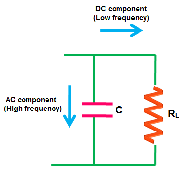 On the other hand, the ac components experience a low resistance from the
capacitor. So the ac components easily passes through the capacitor. Only a
small part of the ac components passes through the load resistor (RL)
producing a small ripple voltage at the output.
The passage of ac components through the capacitor is nothing but charging
of the capacitor.
In simple words, the ac components is nothing but an excess current that
flows through the capacitor and charges it. This prevents any sudden change
in the voltage at the output.
On the other hand, the ac components experience a low resistance from the
capacitor. So the ac components easily passes through the capacitor. Only a
small part of the ac components passes through the load resistor (RL)
producing a small ripple voltage at the output.
The passage of ac components through the capacitor is nothing but charging
of the capacitor.
In simple words, the ac components is nothing but an excess current that
flows through the capacitor and charges it. This prevents any sudden change
in the voltage at the output.
Half Wave Rectifier with Filter O/P Waveforms During the conduction period, the capacitor charges to the maximum value of the supply voltage. When the voltage between the plates of the capacitor is equal to the supply voltage, the capacitor is said to be fully charged.
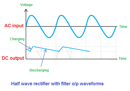 When the capacitor is fully charged, it holds the charge until the input AC
supply to the rectifier reaches the negative half cycle.
When the negative half cycle is reached, the diode D gets reverse biased and
stops allowing electric current through it. During this non-conduction
period, the input voltage is less than that of the capacitor voltage. So the
capacitor discharges all the stored charges through the load resistor RL.
This prevents the output load voltage from falling to zero.
The capacitor discharges until the input supply voltage is less than the
capacitor voltage. When the input supply voltage is greater than the
capacitor voltage, the capacitor again starts charging.
When the positive half cycle is reached again, the diode D is forward biased
and allows electric current. This makes capacitor to charge again.
The capacitor filter with a large discharge time constant will produce a
very smooth DC voltage.
Thus, a smooth and steady DC voltage is obtained by using the filter.
When the capacitor is fully charged, it holds the charge until the input AC
supply to the rectifier reaches the negative half cycle.
When the negative half cycle is reached, the diode D gets reverse biased and
stops allowing electric current through it. During this non-conduction
period, the input voltage is less than that of the capacitor voltage. So the
capacitor discharges all the stored charges through the load resistor RL.
This prevents the output load voltage from falling to zero.
The capacitor discharges until the input supply voltage is less than the
capacitor voltage. When the input supply voltage is greater than the
capacitor voltage, the capacitor again starts charging.
When the positive half cycle is reached again, the diode D is forward biased
and allows electric current. This makes capacitor to charge again.
The capacitor filter with a large discharge time constant will produce a
very smooth DC voltage.
Thus, a smooth and steady DC voltage is obtained by using the filter.