Full Wave Rectifier with Filter
From: https://www.physics-and-radio-electronics.com/electronic-devices-and
-circuits/rectifier/fullwaverectifierwithfilter.html
Full wave rectifier with filter
"This article is about center tapped full wave rectifier with filter. If you
want to read only about center tapped full wave rectifier visit: center tapped
full wave rectifier"
The device that converts Alternating Current (AC) into Direct Current (DC)
is referred to as rectifier.
In half wave rectifier, the conversion of Alternating Current (AC) into
Direct Current (DC) is not efficient. Half wave rectifier allows either
positive half cycle or negative half cycle of the input AC signal and the
remaining half cycle is blocked. As a result, a large power is wasted. Also,
the output Direct Current (DC) produced by the half wave rectifier contains
large ripples. This ripple voltage fluctuates with respect to time. So it is
not suitable for practical applications.
To overcome these problems, we use filters at the output. Even though we use
filters at the output, the DC signal obtained at the output is not a pure
DC. Furthermore, the power loss is high in half wave rectifier. Therefore,
to reduce the power loss and reduce the ripples at the output, we go for
another type of rectifier known as full wave rectifier.
As the name suggests, the full wave rectifier rectifies both positive and
negative half cycles of the input AC signal.
Even though the full wave rectifier rectify both positive and negative half
cycles, the DC signal obtained at the output still contains some ripples. To
reduce these ripples at the output, we use a filter.
The filter is an electronic device that converts the pulsating Direct
Current into pure Direct Current.
The filter is made up of a combination of electronic components such as
resistors, capacitors, and inductors. The property of inductor is that it
allows the DC components and blocks the AC components. The property of a
capacitor is that it allows the AC components and blocks the DC components.
In this tutorial, a center tapped full wave rectifier with a filter made up
of capacitor and resistor is explained. The filter made up of capacitor and
resistor is known as capacitor filter.
In the circuit diagram, the capacitor C is placed across the load resistor
RL.
The working of the full wave rectifier with filter is almost similar to that
of the half wave rectifier with filter. The only difference is that in the
half wave rectifier only one half cycle (either positive or negative) of the
input AC current will charge the capacitor but the remaining half cycle will
not charge the capacitor. But in full wave rectifier, both positive and
negative half cycles of the input AC current will charge the capacitor.
The main duty of the capacitor filter is to short the ripples to the ground
and blocks the pure DC (DC components), so that it flows through the
alternate path and reaches output load resistor RL.
When input AC voltage is applied, during the positive half cycle, the diode
D1 is forward biased and allows electric current whereas the diode D2 is
reverse biased and blocks electric current. On the other hand, during the
negative half cycle the diode D2 is forward biased (allows electric current)
and the diode D1 is reverse biased (blocks electric current).
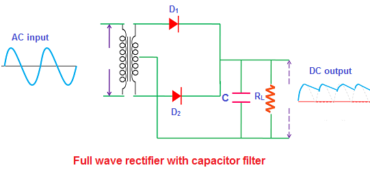 During the positive half cycle, the diode (D1) current reaches the filter
and charges the capacitor. However, the charging of the capacitor happens
only when the applied AC voltage is greater than the capacitor voltage.
Initially, the capacitor is uncharged. That means no voltage exists between
the plates of the capacitor. So when the voltage is turned on, the charging
of the capacitor happens immediately.
During this conduction period, the capacitor charges to the maximum value of
the input supply voltage. The capacitor stores a maximum charge exactly at
the quarter positive half cycle in the waveform. At this point, the supply
voltage is equal to the capacitor voltage.
During the positive half cycle, the diode (D1) current reaches the filter
and charges the capacitor. However, the charging of the capacitor happens
only when the applied AC voltage is greater than the capacitor voltage.
Initially, the capacitor is uncharged. That means no voltage exists between
the plates of the capacitor. So when the voltage is turned on, the charging
of the capacitor happens immediately.
During this conduction period, the capacitor charges to the maximum value of
the input supply voltage. The capacitor stores a maximum charge exactly at
the quarter positive half cycle in the waveform. At this point, the supply
voltage is equal to the capacitor voltage.
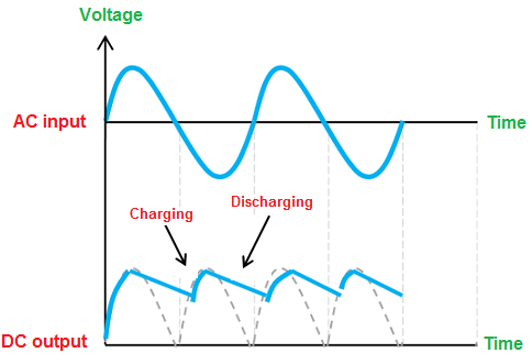 When the AC voltage starts decreasing and becomes less than the capacitor
voltage, then the capacitor starts slowly discharging.
The discharging of the capacitor is very slow as compared to the charging of
the capacitor. So the capacitor does not get enough time to completely
discharged. Before the complete discharge of the capacitor happens, the
charging again takes place. So only half or more than half of the capacitor
charge get discharged.
When the input AC supply voltage reaches the negative half cycle, the diode
D1 is reverse biased (blocks electric current) whereas the diode D2 is
forward biased (allows electric current).
During the negative half cycle, the diode (D2) current reaches the filter
and charges the capacitor. However, the charging of the capacitor happens
only when the applied AC voltage is greater than the capacitor voltage.
The capacitor is not completely uncharged, so the charging of the capacitor
does not happens immediately. When the supply voltage becomes greater than
the capacitor voltage, the capacitor again starts charging.
In both positive and negative half cycles, the current flows in the same
direction across the load resistor RL. So we get either complete positive
half cycles or negative half cycles. In our case, they are complete positive
half cycles.
When the AC voltage starts decreasing and becomes less than the capacitor
voltage, then the capacitor starts slowly discharging.
The discharging of the capacitor is very slow as compared to the charging of
the capacitor. So the capacitor does not get enough time to completely
discharged. Before the complete discharge of the capacitor happens, the
charging again takes place. So only half or more than half of the capacitor
charge get discharged.
When the input AC supply voltage reaches the negative half cycle, the diode
D1 is reverse biased (blocks electric current) whereas the diode D2 is
forward biased (allows electric current).
During the negative half cycle, the diode (D2) current reaches the filter
and charges the capacitor. However, the charging of the capacitor happens
only when the applied AC voltage is greater than the capacitor voltage.
The capacitor is not completely uncharged, so the charging of the capacitor
does not happens immediately. When the supply voltage becomes greater than
the capacitor voltage, the capacitor again starts charging.
In both positive and negative half cycles, the current flows in the same
direction across the load resistor RL. So we get either complete positive
half cycles or negative half cycles. In our case, they are complete positive
half cycles.
How exactly the capacitor filter removes the ripples in the signal
The pulsating Direct Current (DC) produced by the full wave rectifier contains
both AC and DC components.
We know that the capacitor allows the AC components and blocks the DC components
of the current. When the DC current that contains both DC components and AC
components reaches the filter, the DC components experience a high resistance
from the capacitor whereas the AC components experience a low resistance from
the capacitor.
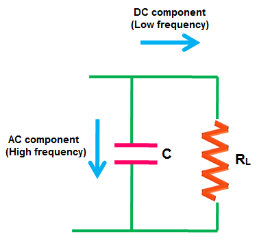 Electric current always prefers to flow through a low resistance path. So the AC
components will flow through the capacitor whereas the DC components are blocked
by the capacitor. Therefore, they find an alternate path and reach the output
load resistor RL. The flow of AC components through the capacitor is nothing but
the charging of a capacitor.
Thus, the filter converts the pulsating DC into pure DC
Electric current always prefers to flow through a low resistance path. So the AC
components will flow through the capacitor whereas the DC components are blocked
by the capacitor. Therefore, they find an alternate path and reach the output
load resistor RL. The flow of AC components through the capacitor is nothing but
the charging of a capacitor.
Thus, the filter converts the pulsating DC into pure DC