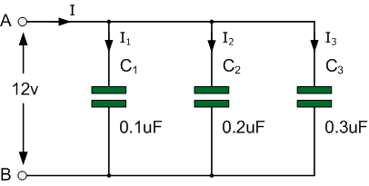
Capacitors are connected together in parallel when both of its terminals are connected to each terminal of another capacitor
| Intro | Parallel Caps Equation | Example 1 | Example 2 |
Capacitors in Parallel

|
Capacitors in Parallel
Capacitors are connected together in parallel when both of its terminals are connected to each terminal of another capacitor |
 When capacitors are connected together in parallel the total or equivalent
capacitance, CT in the circuit is equal to the sum of all the individual
capacitors added together. This is because the top plate of capacitor, C1 is
connected to the top plate of C2 which is connected to the top plate of C3
and so on.
The same is also true of the capacitors bottom plates. Then it is the same
as if the three sets of plates were touching each other and equal to one
large single plate thereby increasing the effective plate area in m2.
Since capacitance, C is related to plate area ( C = ε(A/d) ) the
capacitance value of the combination will also increase. Then the total
capacitance value of the capacitors connected together in parallel is
actually calculated by adding the plate area together. In other words, the
total capacitance is equal to the sum of all the individual capacitance’s
in parallel. You may have noticed that the total capacitance of parallel
capacitors is found in the same way as the total resistance of series
resistors.
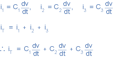
The currents flowing through each capacitor and as we saw in the previous
tutorial are related to the voltage. Then by applying Kirchoff’s Current
Law, ( KCL ) to the above circuit, we have
 Total Circuit Current
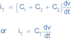
and this can be re-written as:
 total circuit capacitance
Then we can define the total or equivalent circuit capacitance, CT as being
the sum of all the individual capacitance’s add together giving us the
generalized equation of:
 capacitors in parallel equation
When adding together capacitors in parallel, they must all be converted to
the same capacitance units, whether it is μF, nF or pF. Also, we can see
that the current flowing through the total capacitance value, CT is the same
as the total circuit current, iT
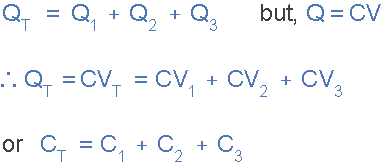
We can also define the total capacitance of the parallel circuit from the
total stored coulomb charge using the Q = CV equation for charge on a
capacitors plates. The total charge QT stored on all the plates equals the
sum of the individual stored charges on each capacitor therefore,
Equivalent Capacitance in Parallel
As the voltage, ( V ) is common for parallel connected capacitors, we can
divide both sides of the above equation through by the voltage leaving just
the capacitance and by simply adding together the value of the individual
capacitances gives the total capacitance, CT. Also, this equation is not
dependent upon the number of Capacitors in Parallel in the branch, and can
therefore be generalized for any number of N parallel capacitors connected
together.
 capacitors connected in parallel
One important point to remember about parallel connected capacitor circuits,
the total capacitance ( CT ) of any two or more capacitors connected
together in parallel will always be GREATER than the value of the largest
capacitor in the group as we are adding together values. So in our example
above CT = 0.6μF whereas the largest value capacitor is only 0.3μF.
When 4, 5, 6 or even more capacitors are connected together the total
capacitance of the circuit CT would still be the sum of all the individual
capacitors added together and as we know now, the total capacitance of a
parallel circuit is always greater than the highest value capacitor.
This is because we have effectively increased the total surface area of the
plates. If we do this with two identical capacitors, we have doubled the
surface area of the plates which in turn doubles the capacitance of the
combination and so on.