Modbus
From: https://www.ni.com/en/shop/seamlessly-connect-to-third-party-devices-and-supervisory-system/the-modbus-protocol-in-depth.html#section-134204970
Modbus Protocol & How Does It Work?
Updated Mar 31, 2023
Overview
Modbus is an industrial protocol that was developed in 1979 to make
communication possible between automation devices. Originally implemented as
an application-level protocol intended to transfer data over a serial layer,
Modbus has expanded to include implementations over serial, TCP/IP, and the
user datagram protocol (UDP). This document provides an in-depth view of the
protocol implementation.
What Is the Modbus Protocol?
Modbus is a request-response protocol implemented using a master-slave
relationship. In a master-slave relationship, communication always occurs in
pairs—one device must initiate a request and then wait for a response—and the
initiating device (the master) is responsible for initiating every interaction.
Typically, the master is a human machine interface (HMI) or Supervisory Control
and Data Acquisition (SCADA) system and the slave is a sensor, programmable
logic controller (PLC), or programmable automation controller (PAC). The
content of these requests and responses, and the network layers across which
these messages are sent, are defined by the different layers of the protocol.
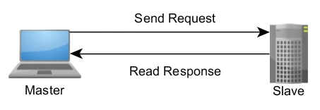 Figure 1. A Master-Slave Networking Relationship
Layers of the Modbus Protocol
In the initial implementation, Modbus was a single protocol built on top of
serial, so it could not be divided into multiple layers. Over time,
different application data units were introduced to either change the
packet format used over serial or to allow the use of TCP/IP and user
datagram protocol (UDP) networks. This led to a separation of the core
protocol, which defines the protocol data unit (PDU), and the network
layer, which defines the application data unit (ADU).
Back to top
Protocol Data Unit
The PDU and the code that handles it comprise the core of the Modbus
Application Protocol Specification. This specification defines the format
of the PDU, the various data concepts used by the protocol, the use of
function codes to access that data, and the specific implementation and
restrictions of each function code.
The Modbus PDU format is defined as a function code followed by an
associated set of data. The size and contents of this data are defined by
the function code, and the entire PDU (function code and data) cannot
exceed 253 bytes in size. Every function code has a specific behavior that
slaves can flexibly implement based on their desired application behavior.
The PDU specification defines core concepts for data access and
manipulation; however, a slave may handle data in a way that is not
explicitly defined in the specification.
Accessing Data in Modbus and the Modbus Data Model
Modbus-accessible data is stored, in general, in one of four data banks or
address ranges: coils, discrete inputs, holding registers, and input
registers. As with much of the specification, the names may vary depending
on the industry or application. For example, holding registers may be
referred to as output registers, and coils may be referred to as digital
or discrete outputs. These data banks define the type and access rights of
the contained data. Slave devices have direct access to this data, which
is hosted locally on the devices. The Modbus-accessible data is generally
a subset of the device’s main memory. In contrast, Modbus masters must
request access to this data through various function codes. The behavior
of each block is described in Table 1.
| Memory Block | Data Type | Master Access | Slave Access
|
| Coils | Boolean | Read/Write | Read/Write
|
| Discrete Inputs | Boolean | Read-only | Read/Write
|
| Holding Registers | Unsigned Word | Read/Write | Read/Write
|
| Input Registers | Unsigned Word | Read-only | Read/Write
|
Table 1. Modbus Data Model Blocks
These blocks give you the ability to restrict or permit access to different
data elements and also to provide simplified mechanisms at the application
layer to access different data types.
The blocks are completely conceptual. They may exist as separate memory
addresses in a given system, but they may also overlap. For example, coil
one may exist in the same location in memory as the first bit of the word
represented by holding register one. The addressing scheme is entirely
defined by the slave device, and its interpretation of each memory block
is an important part of the device’s data model.
Data Model Addressing
The specification defines each block as containing an address space of as
many as 65,536 (216) elements. Within the definition of the PDU, Modbus
defines the address of each data element as ranging from 0 to 65,535.
However, each data element is numbered from 1 to n, where n has a maximum
value of 65,536. That is, coil 1 is in the coil block at address 0, while
holding register 54 is at address 53 in the section of memory that the
slave has defined as holding registers.
The full ranges allowed by the specification are not required to be
implemented by a given device. For example, a device may choose not to
implement coils, discrete inputs, or input registers and instead only use
holding registers 150 through 175 and 200 through 225. This is perfectly
acceptable, and invalid access attempts would be handled through
exceptions.
Data Addressing Ranges
Although the specification defines different data types as existing in
different blocks and assigns a local address range to each type, this does
not necessarily translate into an intuitive addressing scheme for the
purposes of documentation or understanding a given device’s
Modbus-accessible memory. To simplify the discussion of memory block
locations, a numbering scheme was introduced, which added prefixes to the
address of the data in question.
For example, rather than referring to an item as holding register 14 at
address 13, a device manual would refer to a data item at address 4,014,
40,014, or 400,014. In each case, the first number specified is 4 to
represent holding registers, and the address is specified using the
remaining numbers. The difference between 4XXX, 4XXXX, and 4XXXXX depends
on the address space used by the device. If all 65,536 registers are in
use, 4XXXXX notation should be used, as it allows for a range from 400,001
to 465,536. If only a few registers are used, a common practice is to use
the range 4,001 through 4,999.
In this addressing scheme, each data type is assigned a prefix as shown in
Table 2.
| Data Block | Prefix
|
| Coils | 0
|
| Discrete Inputs | 1
|
| Input Registers | 3
|
| Holding Registers | 4
|
Table 2. Data Range Prefixes
Coils exist with a prefix of 0. This means that a reference of 4001 could
refer to either holding register one or coil 4001. For this reason, all
new implementations are recommended to use 6-digit addressing with leading
zeros, and to note this in the documentation. Thus, holding register one
is referenced as 400,001 and coil 4001 is referenced as 004,001.
Data Address Start Values
The difference between memory addresses and reference numbers is further
complicated by the indexing selected by a given application. As mentioned
previously, holding register one is at address zero. Typically, reference
numbers are one-indexed, meaning that the start value of a given range is
one. Thus, 400,001 translates literally to holding register 00001, which
is at address 0. Some implementations choose to start their ranges at
zero, meaning that 400,000 translates to the holding register at address
zero. Table 3 demonstrates this concept.
Address Register Number Number (1-indexing, standard) Number (0-indexing,
alternative)
| Address | Register No. | Number(1-indexing,sandard) | Number(0-indexing,
alternate)
|
| 0 | 1 | 400001 | 400000
|
| 1 | 2 | 400002 | 400001
|
| 2 | 3 | 400003 | 400002
|
Table 3. Register Indexing Schemes
One-indexed ranges are common and strongly recommended. In either case, the
start value for each range should be noted in documentation.
Large Data Types
The Modbus standard supplies a relatively simplistic data model that does
not include additional data types outside of an unsigned word and bit
value. Although this is sufficient for some systems, where the bit values
correspond to solenoids and relays and the word values correspond to
unscaled ADC values, it is insufficient for more advanced systems. As a
result, many Modbus implementations include data types that cross register
boundaries. The NI LabVIEW Datalogging and Supervisory Control (DSC)
Module and KEPServerEX both define a number of reference types. For
example, strings stored in a holding register follow the standard form
(400,001) but are followed by a decimal, the length, and the byte ordering
of the string (400,001.2H, a two character string in holding register 1
where the high byte corresponds to the first character of the string).
This is required because each request has finite size, and so a Modbus
master must know the exact bounds of the string rather than searching for
a length or delimiter like NULL.
Bit Access
In addition to allowing access to data that crosses a register boundary,
some Modbus masters support references to individual bits within a
register. This is beneficial as is allows devices to combine data of every
type in the same memory range without having to split binary data into the
coil and discrete input ranges. This is usually referenced using a decimal
point and the bit index or number, depending on the implementation. That
is, the first bit in the first register may be 400,001.00 or 400,001.01.
It is recommended that any documentation specify the indexing scheme used.
Data Endianness
Multiregister data, like single-precision floating point value, can be
easily transferred in Modbus by splitting the data across two registers.
Because this is not defined by the standard, the endianness (or byte
order) of this split is not defined. Although each unsigned word must be
sent in network (big-endian) byte order to satisfy the standard, many
devices reverse the byte order for multibyte data. Figure 2 shows an
unusual but valid example of this.
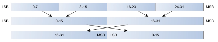 Figure 2. Byte Order Swap for Multiword Data
It is up to the master to understand how the slave is storing information
in memory and to decode it properly. It is recommended that documentation
reflect the word order used by the system. Endianness can also be added as
a system configuration option, with underlying encode and decode
functions, if flexibility in implementation is required.
Figure 2. Byte Order Swap for Multiword Data
It is up to the master to understand how the slave is storing information
in memory and to decode it properly. It is recommended that documentation
reflect the word order used by the system. Endianness can also be added as
a system configuration option, with underlying encode and decode
functions, if flexibility in implementation is required.
Strings
Strings can be easily stored in Modbus registers. For simplicity, some
implementations require that string lengths be multiples of two, with any
additional space filled with null values. Byte order is also a variable in
string interactions. String format may or may not include a NULL as the
final value. As an example of this variability, some devices may store
data as shown in Figure 3.
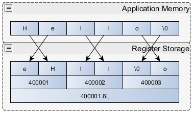 Figure 3. Byte Order Reversal in Modbus Strings
Understanding Function Codes
In contrast to the data model that can vary significantly from device to
device, function codes and their data are defined explicitly by the
standard. Each function follows a pattern. First, the slave validates
inputs like function code, data address, and data range. Then, it executes
the requested action and sends a response appropriate to the code. If any
step in this process fails, an exception is returned to the requestor. The
data transport for these requests is the PDU.
The Modbus PDU
The PDU consists of a one-byte function code followed by up to 252 bytes of
function-specific data.
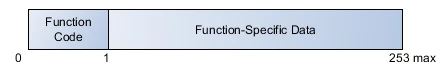 Figure 4. The Modbus PDU
The function code is the first item to be validated. If the function code
is not recognized by the device receiving the request, it responds with an
exception. Should the function code be accepted, the slave device begins
decomposing the data according to the function definition.
Because the packet size is limited to 253 bytes, devices are constrained on
the amount of data that can be transferred. The most common function codes
can transfer between 240 and 250 bytes of actual data from the slave data
model, depending on the code.
Figure 4. The Modbus PDU
The function code is the first item to be validated. If the function code
is not recognized by the device receiving the request, it responds with an
exception. Should the function code be accepted, the slave device begins
decomposing the data according to the function definition.
Because the packet size is limited to 253 bytes, devices are constrained on
the amount of data that can be transferred. The most common function codes
can transfer between 240 and 250 bytes of actual data from the slave data
model, depending on the code.
Slave Function Execution
As defined by the data model, different functions are defined to access
different conceptual blocks of data. A common implementation is to have
codes access static memory locations, but other behaviors are available.
For example, function code 1 (read coils) and 3 (read holding registers)
may access the same physical location in memory. In contrast, function
code 3 (read holding registers) and 16 (write holding registers) may
access completely different locations in memory. Thus, the execution of
each function code is best considered as part of the slave data model
definition.
Regardless of the actual behavior performed, all slave devices are expected
to follow a simple state diagram for each request. Figure 5 shows an
example of this for code 1, read coils.
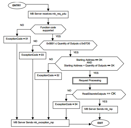 Figure 5. Read Coils State Diagram From the Modbus Protocol Specification
Each slave must validate the function code, the number of inputs, the
starting address, the total range, and the execution of the slave-defined
function that actually performs the read.
Although static address ranges are shown in the state diagram above, the
needs of real-world systems can cause these to vary somewhat from the
defined numbers. In some cases, slave devices cannot transfer the maximum
number of bytes defined by the protocol. That is, rather than allowing a
master to request 0x07D0 inputs, it can only respond with 0x0400.
Similarly, a slave data model may define the range of acceptable coil
values as address 0 through 500. If a master makes a request for 125
starting at address 0, this is OK, but if a master makes the same request
starting at address 400, the final coil will be at address 525, which is
out of range for this device and would result in exception 02 as defined
by the state diagram.
Figure 5. Read Coils State Diagram From the Modbus Protocol Specification
Each slave must validate the function code, the number of inputs, the
starting address, the total range, and the execution of the slave-defined
function that actually performs the read.
Although static address ranges are shown in the state diagram above, the
needs of real-world systems can cause these to vary somewhat from the
defined numbers. In some cases, slave devices cannot transfer the maximum
number of bytes defined by the protocol. That is, rather than allowing a
master to request 0x07D0 inputs, it can only respond with 0x0400.
Similarly, a slave data model may define the range of acceptable coil
values as address 0 through 500. If a master makes a request for 125
starting at address 0, this is OK, but if a master makes the same request
starting at address 400, the final coil will be at address 525, which is
out of range for this device and would result in exception 02 as defined
by the state diagram.
Standard Function Codes
The definition of each standard function code is in the specification. Even
for the most common function codes, there are inevitable mismatches
between the functions enabled on the master and what the slave can handle.
To address this, early versions of the Modbus TCP specification defined
three conformance classes. The official Modbus Conformance Test
Specification does not reference these classes and instead defines
conformance on a per-function basis; however, they can still be convenient
for understanding. It is recommended that any documentation follow the
test specification and define their conformance by which codes they
support, rather than by the legacy classifications.
Class 0 Codes
Class 0 codes are generally considered the bare minimum for a useful Modbus
device, as they give a master the ability to read from or write to the
data model.
| Code | Description
|
| g3 | Read Multiple Registers
|
| g16 | Write Multiple Registers
|
Table 4. Conformance Class 0 Codes
Class 1 Codes
Class 1 function codes consist of the other codes necessary to access all
of the types of the data model. In the original definition, this list
included function code 7 (read exception). However, this code is defined
by the current specification as a serial-only code.
| Code | Description
|
| 1 | Read Coils
|
| 2 | Read Discrete Inputs
|
| 4 | Read Input Registers
|
| 5 | Write Single Coil
|
| 6 | Write Single Register
|
| 7 | Read Exception Status (serial-only)
|
Table 5. Conformance Class 1 Codes
Class 2 Codes
Class 2 function codes are more specialized functions that are less
commonly implemented. For example, Read/Write Multiple Registers may help
reduce the total number of request-response cycles, but the behavior can
still be implemented with class 0 codes.
| Code | Description
|
| 15 | Write Multiple Coils
|
| 20 | Read File Record
|
| 21 | Write File Record
|
| 22 | Mask Write Register
|
| 23 | Read/Write Multiple Registers
|
| 24 | Read FIFO
|
Table 6. Conformance Class 2 Codes
Modbus Encapsulated Interface
The Modbus encapsulated interface (MEI) code, function 43, is used to
encapsulate other data within a Modbus packet. At present, two MEI numbers
are available, 13 (CANopen) and 14 (Device Identification).
Function 43/14 (Device Identification) is useful in that it allows for the
transfer of up to 256 unique objects. Some of these objects are predefined
and reserved, such as vendor name and product code, but applications can
define other objects to transfer as generic data sets.
This code is not commonly implemented.
Exceptions
Slaves use exceptions to indicate a number of bad conditions, from a
malformed request to incorrect inputs. However, exceptions can also be
generated as an application-level response to an invalid request. Slaves
do not respond to requests issued with an exception. Instead, the slave
ignores incomplete or corrupted requests and begins waiting for a new
incoming message.
Exceptions are reported in a defined packet format. First, a function code
is returned to the requesting master equal to the original function code,
except with its most significant bit set. This is equivalent to adding
0x80 to the value of the original function code. In lieu of the normal
data associated with a given function response, exception responses
include a single exception code.
Within the standard, the four most common exception codes are 01, 02, 03,
and 04. These are shown in Table 7 with standard meanings by each
function.
| Exception Code | Meaning
|
| 01 | The received function code is not supported. To confirm the original
function code, subtract 0x80 from the returned value.
|
| 02 | The request attempted to access an invalid address. In the standard,
this can happen only if the starting address and the requested number of
values exceeds 216. However, some devices may restrict this address space
in their data model.
|
| 03 | The request had incorrect data. In some cases, this means that there
was a parameter mismatch, for example between the number of registers sent
and the “byte count” field. More commonly, the master requested more
data than either the slave or protocol allows. For example, a master may
read only 125 holding registers at a time, and resource-limited devices
may restrict this value to even fewer registers.
|
| 04 | An unrecoverable error occurred while attempting to process the
request. This is a catchall exception code that indicates the request was
valid, but the slave could not execute it.
|
Table 7. Common Modbus Exception Codes
The state diagram for every function code should cover at least exception
code 01 and usually includes exception code 04, 02, 03, and any other
defined exception codes are optional.
Application Data Unit
In addition to the functionality defined at the PDU core of the Modbus
protocol, you can use multiple network protocols. The most common
protocols are serial and TCP/IP, but you can use others like UDP as well.
To transmit data necessary for Modbus across these layers, Modbus includes
a set of ADU variants that are tailored to each network protocol.
Common Features
Modbus requires certain features to provide reliable communication. The
Unit ID or Address is used in each ADU format to provide routing
information to the application layer. Each ADU comes with a full PDU,
which includes the function code and associated data for a given request.
For reliability, each message includes error-checking information.
Finally, all ADUs provide a mechanism for determining the beginning and
end of a request frame, but implements these differently.
Standard Formats
The three standard ADU formats are TCP, remote terminal unit (RTU), and
ASCII. RTU and ASCII ADUs are traditionally used over a serial line, while
TCP is used over modern TCP/IP or UDP/IP networks.
TCP/IP
The TCP ADUs consists of the Modbus Application Protocol (MBAP) Header
concatenated with the Modbus PDU. The MBAP is a general-purpose header
that depends on a reliable networking layer. The format of this ADU,
including the header, is shown in Figure 6.
 Figure 6. The TCP/IP ADU
The data fields of the header indicate its use. First, it includes a
transaction identifier. This is valuable on a network where multiple
requests can be outstanding simultaneously. That is, a master can send
requests 1, 2, and 3. At some later point, a slave can respond in the
order 2, 1, 3, and the master can match the requests to the responses and
parse data accurately. This is useful for Ethernet networks.
The protocol identifier is normally zero, but you can use it to expand the
behavior of the protocol. The length field is used by the protocol to
delineate the length of the rest of the packet. The location of this
element also indicates the dependency of this header format on a reliable
networking layer. Because TCP packets have built-in error checking and
ensure data coherency and delivery, packet length can be located anywhere
in the header. On a less inherently reliable network such as a serial
network, a packet could be lost, having the effect that even if the stream
of data read by the application included valid transaction and protocol
information, corrupted length information would make the header invalid.
TCP provides a reasonable amount of protection against this situation.
The Unit ID is typically unused for TCP/IP devices. However, Modbus is such
a common protocol that many gateways are developed, which convert the
Modbus protocol into another protocol. In the original intended use case,
a Modbus TCP/IP to serial gateway could be used to allow connection
between new TCP/IP networks and older serial networks. In such an
environment, the Unit ID is used to determine the address of the slave
device that the PDU is actually intended for.
Finally, the ADU includes a PDU. The length of this PDU is still limited to
253 bytes for the standard protocol.
Figure 6. The TCP/IP ADU
The data fields of the header indicate its use. First, it includes a
transaction identifier. This is valuable on a network where multiple
requests can be outstanding simultaneously. That is, a master can send
requests 1, 2, and 3. At some later point, a slave can respond in the
order 2, 1, 3, and the master can match the requests to the responses and
parse data accurately. This is useful for Ethernet networks.
The protocol identifier is normally zero, but you can use it to expand the
behavior of the protocol. The length field is used by the protocol to
delineate the length of the rest of the packet. The location of this
element also indicates the dependency of this header format on a reliable
networking layer. Because TCP packets have built-in error checking and
ensure data coherency and delivery, packet length can be located anywhere
in the header. On a less inherently reliable network such as a serial
network, a packet could be lost, having the effect that even if the stream
of data read by the application included valid transaction and protocol
information, corrupted length information would make the header invalid.
TCP provides a reasonable amount of protection against this situation.
The Unit ID is typically unused for TCP/IP devices. However, Modbus is such
a common protocol that many gateways are developed, which convert the
Modbus protocol into another protocol. In the original intended use case,
a Modbus TCP/IP to serial gateway could be used to allow connection
between new TCP/IP networks and older serial networks. In such an
environment, the Unit ID is used to determine the address of the slave
device that the PDU is actually intended for.
Finally, the ADU includes a PDU. The length of this PDU is still limited to
253 bytes for the standard protocol.
RTU
The RTU ADU appears to be much simpler, as shown in Figure 7.
 Figure 7. The RTU ADU
Unlike the more complex TCP/IP ADU, this ADU includes only two pieces of
information in addition to the core PDU. First, an address is used to
define which slave a PDU is intended for. On most networks, an address of
0 defines the “broadcast” address. That is, a master may send an
output command to address 0 and all slaves should process the request but
no slave should respond. Besides this address, a CRC is used to ensure the
integrity of the data.
However, the reality of the situation in more modern implementations is far
from simple. Bracketing the packet is a pair of silent times—that is,
periods where there is no communication on the bus. For a baud rate of
9,600, this rate is around 4 ms. The standard defines a minimum silence
length, regardless of baud rate, of just under 2 ms.
First, this has a performance drawback as the device must wait for the idle
time to complete before the packet can be processed. More dangerous,
however, is the introduction of different technologies used for serial
transfer and much faster baud rates than when the standard was introduced.
With a USB-to-serial converter cable, for example, you have no control
over the packetization and transfer of data. Testing shows that using a
USB-to-serial cable with the NI-VISA driver introduces large, variably
sized gaps in the data stream, and these gaps—periods of silence—trick
specification-compliant code into believing that a message is complete.
Because the message is not complete, this usually leads to an invalid CRC
and to the device interpreting the ADU as being corrupted.
In addition to issues with transmission, modern driver technologies
abstract serial communication significantly and typically require a
polling mechanism from the application code. For example, neither the .NET
Framework 4.5 SerialPort Class nor the NI-VISA driver provide a mechanism
for detecting silence on a serial line except by polling the bytes on the
port. This results in a sliding scale of poor performance (if polling is
performed too slowly) or high CPU usage (if polling is performed too
quickly).
A common method for addressing these issues is to break the layer of
abstraction between the Modbus PDU and the networking layer. That is, the
serial code interrogates the Modbus PDU packet to determine the function
code. Combined with other data in the packet, the length of the remaining
packet can be discovered and used to determine the end of the packet. With
this information, a much longer time-out can be used, allowing for
transmission gaps, and application-level polling can occur much more
slowly. This mechanism is recommended for new development. Code that does
not employ this may experience a larger than expected number of
“corrupted” packets.
Figure 7. The RTU ADU
Unlike the more complex TCP/IP ADU, this ADU includes only two pieces of
information in addition to the core PDU. First, an address is used to
define which slave a PDU is intended for. On most networks, an address of
0 defines the “broadcast” address. That is, a master may send an
output command to address 0 and all slaves should process the request but
no slave should respond. Besides this address, a CRC is used to ensure the
integrity of the data.
However, the reality of the situation in more modern implementations is far
from simple. Bracketing the packet is a pair of silent times—that is,
periods where there is no communication on the bus. For a baud rate of
9,600, this rate is around 4 ms. The standard defines a minimum silence
length, regardless of baud rate, of just under 2 ms.
First, this has a performance drawback as the device must wait for the idle
time to complete before the packet can be processed. More dangerous,
however, is the introduction of different technologies used for serial
transfer and much faster baud rates than when the standard was introduced.
With a USB-to-serial converter cable, for example, you have no control
over the packetization and transfer of data. Testing shows that using a
USB-to-serial cable with the NI-VISA driver introduces large, variably
sized gaps in the data stream, and these gaps—periods of silence—trick
specification-compliant code into believing that a message is complete.
Because the message is not complete, this usually leads to an invalid CRC
and to the device interpreting the ADU as being corrupted.
In addition to issues with transmission, modern driver technologies
abstract serial communication significantly and typically require a
polling mechanism from the application code. For example, neither the .NET
Framework 4.5 SerialPort Class nor the NI-VISA driver provide a mechanism
for detecting silence on a serial line except by polling the bytes on the
port. This results in a sliding scale of poor performance (if polling is
performed too slowly) or high CPU usage (if polling is performed too
quickly).
A common method for addressing these issues is to break the layer of
abstraction between the Modbus PDU and the networking layer. That is, the
serial code interrogates the Modbus PDU packet to determine the function
code. Combined with other data in the packet, the length of the remaining
packet can be discovered and used to determine the end of the packet. With
this information, a much longer time-out can be used, allowing for
transmission gaps, and application-level polling can occur much more
slowly. This mechanism is recommended for new development. Code that does
not employ this may experience a larger than expected number of
“corrupted” packets.
ASCII
The ASCII ADU is more complex than RTU as shown in Figure 8, but also
avoids
many of the issues of the RTU packet. However, it has some of its own
disadvantages.
 Figure 8. The ASCII ADU
Resolving the issue of determining packet size, the ASCII ADU has a
well-defined and unique start and end for each packet. That is, each
packet begins with “:” and ends with a carriage return (CR) and line
feed (LF). In addition, serial APIs like NI-VISA and the .NET Framework
SerialPort Class can easily read data in a buffer until a specific
character—like CR/LF—is received. These features make it easy to
process the stream of data on the serial line efficiently in modern
application code.
The downside of the ASCII ADU is that all data is transferred as
hexadecimal characters encoded in ASCII. That is, rather than sending a
single byte for the function code 3, 0x03, it sends the ASCII characters
“0” and “3,” or 0x30/0x33. This makes the protocol more
human-readable, but also means that twice as much data must be transferred
across the serial network and that the sending and receiving applications
must be capable of parsing the ASCII values.
Figure 8. The ASCII ADU
Resolving the issue of determining packet size, the ASCII ADU has a
well-defined and unique start and end for each packet. That is, each
packet begins with “:” and ends with a carriage return (CR) and line
feed (LF). In addition, serial APIs like NI-VISA and the .NET Framework
SerialPort Class can easily read data in a buffer until a specific
character—like CR/LF—is received. These features make it easy to
process the stream of data on the serial line efficiently in modern
application code.
The downside of the ASCII ADU is that all data is transferred as
hexadecimal characters encoded in ASCII. That is, rather than sending a
single byte for the function code 3, 0x03, it sends the ASCII characters
“0” and “3,” or 0x30/0x33. This makes the protocol more
human-readable, but also means that twice as much data must be transferred
across the serial network and that the sending and receiving applications
must be capable of parsing the ASCII values.
Extending Modbus
Modbus, a relatively simple and open standard, can be modified to suit the
needs of a given application. This is most common for communication
between an HMI and PLC or PAC, as this is a situation in which a single
organization has control over both endpoints of the protocol. Developers
of sensors, for example, are more likely to adhere to the written standard
because they typically only control the implementation of their slave, and
interoperability is desirable.
In general, modifying the protocol is not recommended. This section is
merely provided as an acknowledgment of the mechanisms that others have
used to adjust the behavior of the protocol.
New Function Codes
Some function codes are defined, but the Modbus standard does allow you to
develop additional function codes. Specifically, function codes 1 through
64, 73 through 99, and 111 through 127 are public codes that are reserved
and guaranteed to be unique. The remaining codes, 65 through 72 and 100
through 110, are for user-defined use. With these user-defined codes, you
can use any data structure. Data can even exceed the standard 253 byte
limit for the Modbus PDU, but the entire application should be validated
to ensure that other layers work as expected when the PDU exceeds the
standard limit. Function codes above 127 are reserved for exception
responses.
Network Layers
Modbus can run on many network layers besides serial and TCP. A potential
implementation is UDP because it is suited to the Modbus communication
style. Modbus is a message-based protocol at its core, so UDP’s ability
to send a well-defined packet of information without any additional
application-level information, like a start character or length, makes
Modbus extremely simple to implement. Rather than require an additional
ADU or reuse an existing ADU, Modbus PDU packets can be sent using a
standard UDP API and be received fully formed on the other end. Although
TCP is advantageous for some protocols because of the built-in
acknowledgement system, Modbus performs acknowledgement at the application
layer. However, using UDP in this way does eliminate the transaction
identifier field in the TCP ADU, which rids the possibility of multiple
simultaneous outstanding transactions. Therefore, the master must be a
synchronous master or the UDP packet must have an identifier to help the
master organize requests and responses. A suggested implementation would
be to use the TCP/IP ADU on a UDP network layer.
ADU Modifications
Finally, an application could choose to modify an ADU, or use unutilized
portions of an existing ADU like TCP. For example, TCP defines a 16-bit
length field, a 16-bit protocol, and an 8-bit unit ID. Given that the
largest Modbus PDU is 253 bytes, the high byte of the length field is
always zero. For Modbus/TCP, the protocol field and unit ID are always
zero. A simple extension of the protocol might send three packets
simultaneously by changing the protocol field to a non-zero number and
using the two unused bytes (unit ID and the high byte of the length field)
to send the lengths of two additional PDUs (see Figure 9).
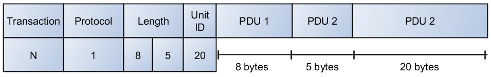 Figure 9. Sample Modification of the TCP ADU
Additional Resources