Push button with ESP32 – GPIO pins as digital input
Push button with ESP32 – GPIO pins as digital input, In this fifth tutorial on a
series of ESP32 tutorials, we will teach you how to use GPIO pins of ESP32 as
digital input pins and how to interface a push button with the ESP32 development
board. The push button is used to control device like turning on and off a light
emitting diode when the push button is pressed or not. Similarly, we can use
push button to increase or decrease speed of dc motor. When you use push button
with ESP32, we have to use GPIO pins as digital input pins. Because we will read
the state of the push button. The push button will give two logical states
either high or low.
In the last tutorial, we have learned how to use GPIO pins of ESP32 as digital
output pins by creating an LED blinking example:
GPIO pins of ESP32 – LED Blinking example
We have a similar guide with MicroPython:
ESP32 and ESP8266 GPIO Programming with MicroPython – LED Blinking Example
Push Button Interfacing Configurations
There are two configuration modes to interface a push button with ESP32 board.
Let’s discuss both these modes one by one.
Pull-Up Mode
In Pull-up mode, when a push button is not pressed, a logic high input appears
on the ESP32 GPIO pin. Because a 5V signal appears on the input terminal through
an R1 resistor. On the contrary, when the push button is pressed, metallic
contacts of the push button make contact with the ground terminal and the input
terminal. Therefore, a logic low input reflects on the digital input pin of the
ESP32 board. In short, by reading this state of the push button with a digital
input pin of a microcontroller, we can identify whether a push button is pressed
or not. The following schematic diagram shows the connection of a push button
with a pull-up resistor.
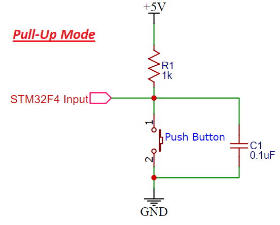 Schematic Pullup resistor STM32F4
Pull-Down Mode
In Pull-down mode, when a push button is not pressed, a logic low input appears
on the ESP32 GPIO pin. Because a ground reference signal appears on the input
terminal through an R1 resistor. On the contrary, when the push button is
pressed, metallic contacts of the push button make contact with the +5V signal
and the input terminal. Therefore, a logic high input reflects on the digital
input pin of ESP32 board. The following schematic diagram shows the connection
of a push button with a pull-up resistor.
Schematic Pullup resistor STM32F4
Pull-Down Mode
In Pull-down mode, when a push button is not pressed, a logic low input appears
on the ESP32 GPIO pin. Because a ground reference signal appears on the input
terminal through an R1 resistor. On the contrary, when the push button is
pressed, metallic contacts of the push button make contact with the +5V signal
and the input terminal. Therefore, a logic high input reflects on the digital
input pin of ESP32 board. The following schematic diagram shows the connection
of a push button with a pull-up resistor.
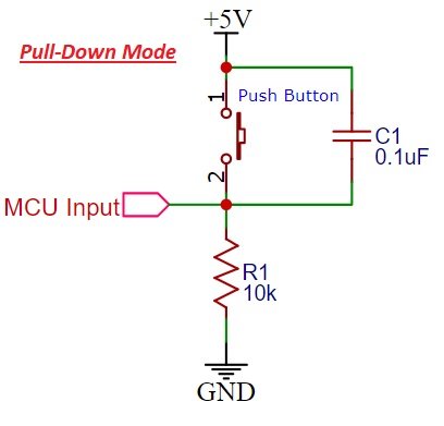 Pull down resistor with Push button Schematic
Push button interfacing with ESP32
The push button can be interfaced with ESP32 either through pull up resistor
or pull-down resistor. In Pull up resistor mode, when the push button is not
pressed, input to GPIO pin will be logical high or vice versa.
In pull-down resistor mode, when the push button is pressed, input to GPIO
pin will be logic low state and otherwise logic high state.
So We will use digital input pin of ESP32 development board to read this logical
and logical low state using pinMode function of Arduino IDE. So now let’s start
with a circuit diagram of push button interfacing with esp32 and after that I
will explain the programming part.
If you are a beginner and do not have an idea about ESP32 development board, you
can check this guide:
Getting started with the ESP32 development board
Arduino IDE is used to program ESP32 in these series of tutorial and we can
install ESP32 board in Arduino IDE. You can check this tutorial:
How to install ESP32 library in Arduino IDE
Pull down resistor with Push button Schematic
Push button interfacing with ESP32
The push button can be interfaced with ESP32 either through pull up resistor
or pull-down resistor. In Pull up resistor mode, when the push button is not
pressed, input to GPIO pin will be logical high or vice versa.
In pull-down resistor mode, when the push button is pressed, input to GPIO
pin will be logic low state and otherwise logic high state.
So We will use digital input pin of ESP32 development board to read this logical
and logical low state using pinMode function of Arduino IDE. So now let’s start
with a circuit diagram of push button interfacing with esp32 and after that I
will explain the programming part.
If you are a beginner and do not have an idea about ESP32 development board, you
can check this guide:
Getting started with the ESP32 development board
Arduino IDE is used to program ESP32 in these series of tutorial and we can
install ESP32 board in Arduino IDE. You can check this tutorial:
How to install ESP32 library in Arduino IDE
 Push button and LED ESP32
So now let’s perform a simple example to connect a push button with any GPIO pin
and turn on an LED connected to another digital pin.
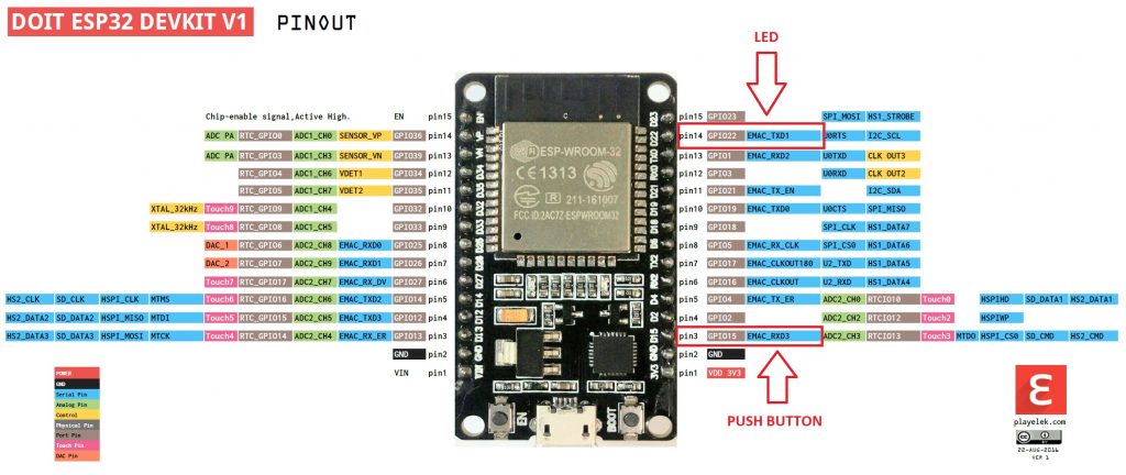
As shown in the above pinout, we will be using GPIO15 to connect the push button
and GPIO22 to connect a push button. We can use any GPIO pin either as digital
input or digital output pins except few GPIO pins which can be used only as
digital input pins for more information about it check ESP32 pin out the
tutorial.
Circuit diagram of Push button with ESP32
Schematic is for push button interfacing is shown below:
Push button and LED ESP32
So now let’s perform a simple example to connect a push button with any GPIO pin
and turn on an LED connected to another digital pin.
As shown in the above pinout, we will be using GPIO15 to connect the push button
and GPIO22 to connect a push button. We can use any GPIO pin either as digital
input or digital output pins except few GPIO pins which can be used only as
digital input pins for more information about it check ESP32 pin out the
tutorial.
Circuit diagram of Push button with ESP32
Schematic is for push button interfacing is shown below:
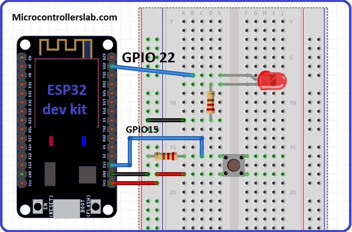 Push button interfacing with ESP32
In the above circuit diagram, GPIO22 is connected with anode pin of LED and
another pin of LED is connected with ground through 330ohm resistor. you can
check LED blinking tutorial for more information about it.
Next push button one terminal is connected with 3.3 volts of ESP32 and other
terminals of a push button is common with GPIO15 and resistor.
Another end of the resistor is connected with a ground. When pushbutton is
not pressed, logic low will appear on GPIO15 or push button state will be low
and when the push button is pressed, a logic high will be on GPIO15.
So we will read these two states of the push button and turn on and turn off
LED accordingly.
Code
Code for push button interfacing is given below. All the functions used in this
code the same as used in the last tutorial on LED blinking except one function
digitalRead function. So I will explain digital read function now:
digitalRead(Pin_number): Digital read function is used to read the state of the
input pin. This digitalRead function returns either logical HIGH or logical LOW
input. If input state of the pin is HIGH, it will return HIGH and otherwise low.
You only need to pass pin number as a augment to this function. For example in
this tutorial, we are using pin number 15 as a digital input, so we will use
this function like this digitalRead(22) or we can define 22 with any name and
use name instead of pin number as we did in the example code below:
/*H********************************************************************
*
**********************************************************************/
// We assigned a name LED pin to pin number 22
const int LEDPIN = 22;
// this will assign the name PushButton to pin numer 15
const int PushButton
// This Setup function is used to initialize everything
/*F********************************************************************
*
**********************************************************************/
void
setup()
{
// This statement will declare pin 22 as digital output
pinMode( LEDPIN, OUTPUT);
// This statement will declare pin 15 as digital input
pinMode( PushButton, INPUT);
}
/*F********************************************************************
*
**********************************************************************/
void
loop()
{
// digitalRead function stores the Push button state
// in variable push_button_state
int Push_button_state = digitalRead(PushButton);
// if condition checks if push button is pressed
// if pressed LED will turn on otherwise remain off
if ( Push_button_state == HIGH )
digitalWrite(LEDPIN, HIGH);
else
digitalWrite(LEDPIN, LOW);
}
So this is the simple code used to read the state of push button or any switch.
So let’s see how the code works?
In code first 2 lines give a name to input pin 15 as PushButton and output
pin 22 as LEDPIN. So now inside the code, we can use these name instead of pin
numbers.
In setup() function, we use pinMode() function to initialize PushButton pin
as an INPUT and LEDPIN as an INPUT.
In loop() function, digitalRead function read the state of the push button
and stores its value in variable Push_button_state.
After that, if condition is used to check the state of variable
Push_button_state.
If Push_button_state gives output HIGH, LEDPIN will be turned on and
otherwise, it will remain off.
After going through this guide, you will surely able to use GPIO pins of ESP32
as a digital input pins. You can also check other ESP32 tutorials:
Analog to digital converter channels of ESP32 and measuring voltage
tutorial
Push button interfacing with ESP32
In the above circuit diagram, GPIO22 is connected with anode pin of LED and
another pin of LED is connected with ground through 330ohm resistor. you can
check LED blinking tutorial for more information about it.
Next push button one terminal is connected with 3.3 volts of ESP32 and other
terminals of a push button is common with GPIO15 and resistor.
Another end of the resistor is connected with a ground. When pushbutton is
not pressed, logic low will appear on GPIO15 or push button state will be low
and when the push button is pressed, a logic high will be on GPIO15.
So we will read these two states of the push button and turn on and turn off
LED accordingly.
Code
Code for push button interfacing is given below. All the functions used in this
code the same as used in the last tutorial on LED blinking except one function
digitalRead function. So I will explain digital read function now:
digitalRead(Pin_number): Digital read function is used to read the state of the
input pin. This digitalRead function returns either logical HIGH or logical LOW
input. If input state of the pin is HIGH, it will return HIGH and otherwise low.
You only need to pass pin number as a augment to this function. For example in
this tutorial, we are using pin number 15 as a digital input, so we will use
this function like this digitalRead(22) or we can define 22 with any name and
use name instead of pin number as we did in the example code below:
/*H********************************************************************
*
**********************************************************************/
// We assigned a name LED pin to pin number 22
const int LEDPIN = 22;
// this will assign the name PushButton to pin numer 15
const int PushButton
// This Setup function is used to initialize everything
/*F********************************************************************
*
**********************************************************************/
void
setup()
{
// This statement will declare pin 22 as digital output
pinMode( LEDPIN, OUTPUT);
// This statement will declare pin 15 as digital input
pinMode( PushButton, INPUT);
}
/*F********************************************************************
*
**********************************************************************/
void
loop()
{
// digitalRead function stores the Push button state
// in variable push_button_state
int Push_button_state = digitalRead(PushButton);
// if condition checks if push button is pressed
// if pressed LED will turn on otherwise remain off
if ( Push_button_state == HIGH )
digitalWrite(LEDPIN, HIGH);
else
digitalWrite(LEDPIN, LOW);
}
So this is the simple code used to read the state of push button or any switch.
So let’s see how the code works?
In code first 2 lines give a name to input pin 15 as PushButton and output
pin 22 as LEDPIN. So now inside the code, we can use these name instead of pin
numbers.
In setup() function, we use pinMode() function to initialize PushButton pin
as an INPUT and LEDPIN as an INPUT.
In loop() function, digitalRead function read the state of the push button
and stores its value in variable Push_button_state.
After that, if condition is used to check the state of variable
Push_button_state.
If Push_button_state gives output HIGH, LEDPIN will be turned on and
otherwise, it will remain off.
After going through this guide, you will surely able to use GPIO pins of ESP32
as a digital input pins. You can also check other ESP32 tutorials:
Analog to digital converter channels of ESP32 and measuring voltage
tutorial