|
|
| 15 ADC channels | 15 channels of 12-bit SAR ADC with selectable ranges of 0
-1V, 0-1.4V, 0-2V, or 0-4V
|
| 2 UART interfaces | 2 UART interfaces with flow control and IrDA support
|
| 25 PWM outputs | 25 PWM pins to control things like motor speed or LED
brightness
|
| 2 DAC channels | Two 8-bit DACs to generate true analog voltages
|
| SPI, I2C and I2S interface | Three SPI and one I2C interfaces for
connecting
various sensors and peripherals, as well as two I2S interfaces for adding
sound to your project
|
| 9 Touch Pads | 9 GPIOs with capacitive touch sensing
|
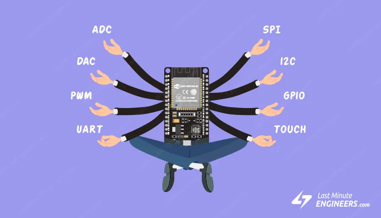
Thanks to the ESP32’s pin multiplexing feature, which allows multiple
peripherals to share a single GPIO pin. For example, a single GPIO pin can
act as an ADC input, DAC output, or touch pad.
For extensive information about the ESP32, please refer to the datasheet.
| Label | GPIO | Safe to use? | Reason
|
| D0 | 0 | | must be HIGH during boot and LOW for programming
|
| TX0 | 1 | | Tx pin, used for flashing and debugging
|
| D2 | 2 | | must be LOW during boot and also connected to the on-board LED
|
| RX0 | 3 | | Rx pin, used for flashing and debugging
|
| D4 | 4 | |
|
| D5 | 5 | | must be HIGH during boot
|
| D6 | 6 | | Connected to Flash memory
|
| D7 | 7 | | Connected to Flash memory
|
| D8 | 8 | | Connected to Flash memory
|
| D9 | 9 | | Connected to Flash memory
|
| D10 | 10 | | Connected to Flash memory
|
| D11 | 11 | | Connected to Flash memory
|
| D12 | 12 | | must be LOW during boot
|
| D13 | 13 | |
|
| D14 | 14 | |
|
| D15 | 15 | | must be HIGH during boot, prevents startup log if pulled LOW
|
| RX2 | 16 | |
|
| TX2 | 17 | |
|
| D18 | 18 | |
|
| D19 | 19 | |
|
| D21 | 21 | |
|
| D22 | 22 | |
|
| D23 | 23 | |
|
| D25 | 25 | |
|
| D26 | 26 | |
|
| D27 | 27 | |
|
| D32 | 32 | |
|
| D33 | 33 | |
|
| D34 | 34 | | Input only GPIO, cannot be configured as output
|
| D35 | 35 | | Input only GPIO, cannot be configured as output
|
| VP | 36 | | Input only GPIO, cannot be configured as output
|
| VN | 39 | | Input only GPIO, cannot be configured as output
|
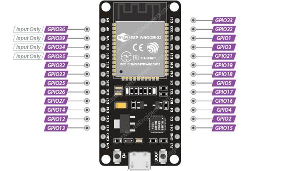
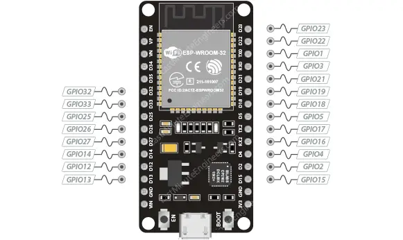
The image below shows which GPIO pins can be used safely.
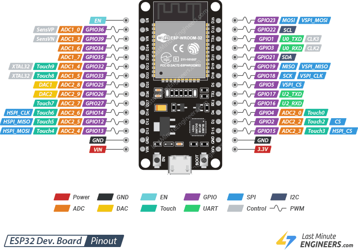
 One of the advantages of the ESP32 is that it has a lot more GPIOs than the
ESP8266. You won’t have to juggle or multiplex your IO pins. However,
there are a few things to keep in mind, so please read the pinout
carefully.
Note:
Please note that the following pinout reference is for the popular 30-pin
ESP32 devkit v1 development board.
One of the advantages of the ESP32 is that it has a lot more GPIOs than the
ESP8266. You won’t have to juggle or multiplex your IO pins. However,
there are a few things to keep in mind, so please read the pinout
carefully.
Note:
Please note that the following pinout reference is for the popular 30-pin
ESP32 devkit v1 development board.
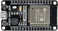 30pin esp32 dev board
Not every ESP32 development board exposes every pin, but each pin works
exactly the same no matter which development board you use.
30pin esp32 dev board
Not every ESP32 development board exposes every pin, but each pin works
exactly the same no matter which development board you use.
 ESP32 GPIO Pins
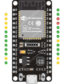 ESP32 GPIO Pins that are Safe to Use
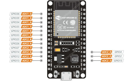 The ESP32’s ADC is a 12-bit ADC, which means it can detect 4096 (2^12) discrete
analog levels. In other words, it will convert input voltages ranging from 0 to
3.3V (operating voltage) into integer values ranging from 0 to 4095. This
results in a resolution of 3.3 volts / 4096 units, or 0.0008 volts (0.8 mV) per
unit.
Moreover, the ADC resolution and channel range can be set programmatically.
The ESP32’s ADC is a 12-bit ADC, which means it can detect 4096 (2^12) discrete
analog levels. In other words, it will convert input voltages ranging from 0 to
3.3V (operating voltage) into integer values ranging from 0 to 4095. This
results in a resolution of 3.3 volts / 4096 units, or 0.0008 volts (0.8 mV) per
unit.
Moreover, the ADC resolution and channel range can be set programmatically.
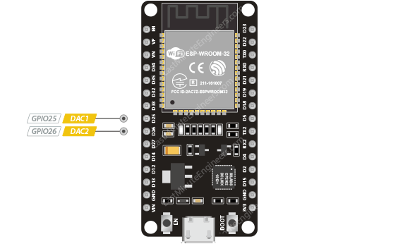 ESP32 DAC Pins
These DACs have an 8-bit resolution, which means that values ranging from 0 to
256 will be converted to an analog voltage ranging from 0 to 3.3V.
The DAC’s 8-bit resolution may be insufficient for use in audio applications, in
which case an external DAC with a higher resolution (12-24 bits) is preferable.
ESP32 DAC Pins
These DACs have an 8-bit resolution, which means that values ranging from 0 to
256 will be converted to an analog voltage ranging from 0 to 3.3V.
The DAC’s 8-bit resolution may be insufficient for use in audio applications, in
which case an external DAC with a higher resolution (12-24 bits) is preferable.
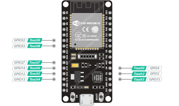 ESP32 Touch Pins
You can make a touch pad by attaching any conductive object to these pins, such
as aluminum foil, conductive cloth, conductive paint, and so on. Because of the
low-noise design and high sensitivity of the circuit, relatively small pads can
be made.
Additionally, these capacitive touch pins can be used to wake the ESP32 from
deep sleep.
ESP32 Touch Pins
You can make a touch pad by attaching any conductive object to these pins, such
as aluminum foil, conductive cloth, conductive paint, and so on. Because of the
low-noise design and high sensitivity of the circuit, relatively small pads can
be made.
Additionally, these capacitive touch pins can be used to wake the ESP32 from
deep sleep.
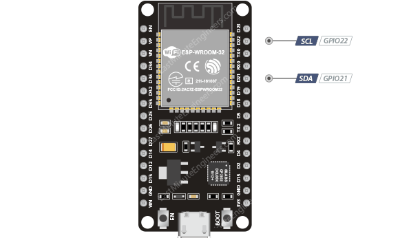 ESP32 I2C Pins
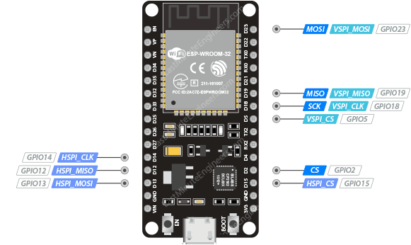 ESP32 SPI Pins
Only VSPI and HSPI are usable SPI interfaces, and the third SPI bus is used by
the integrated flash memory chip. VSPI pins are commonly used in standard
libraries.
ESP32 SPI Pins
Only VSPI and HSPI are usable SPI interfaces, and the third SPI bus is used by
the integrated flash memory chip. VSPI pins are commonly used in standard
libraries.
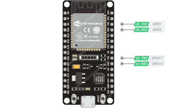 ESP32 UART Pins
In addition, UART provides hardware management of the CTS and RTS signals
and software flow control (XON and XOFF) as well.
ESP32 UART Pins
In addition, UART provides hardware management of the CTS and RTS signals
and software flow control (XON and XOFF) as well.
 ESP32 PWM Pins
The PWM controller consists of PWM timers, the PWM operator and a dedicated
capture sub-module. Each timer provides timing in synchronous or independent
form, and each PWM operator generates a waveform for one PWM channel. The
dedicated capture sub-module can accurately capture events with external timing.
ESP32 PWM Pins
The PWM controller consists of PWM timers, the PWM operator and a dedicated
capture sub-module. Each timer provides timing in synchronous or independent
form, and each PWM operator generates a waveform for one PWM channel. The
dedicated capture sub-module can accurately capture events with external timing.
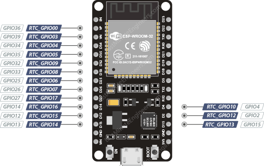 ESP32 RTC GPIO Pins
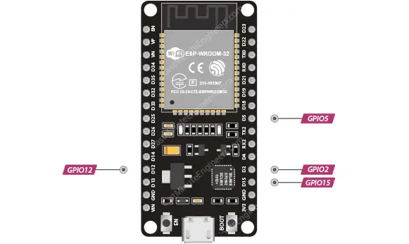 esp32 strapping pins
These pins are used to put the ESP32 into BOOT mode (to run the program
stored in the flash memory) or FLASH mode (to upload the program to the
flash memory). Depending on the state of these pins, the ESP32 will enter
BOOT mode or FLASH mode at power on.
On most development boards with built-in USB/Serial, you don’t need to
worry about the state of these pins, as the board puts them in the correct
state for flashing or boot mode.
However, if peripherals are connected to these pins, you may encounter
issues when attempting to upload new code or flash the ESP32 with new
firmware, as these peripherals prevent the ESP32 from entering the correct
mode.
The strapping pins function normally after reset release, but they should
still be used with caution.
esp32 strapping pins
These pins are used to put the ESP32 into BOOT mode (to run the program
stored in the flash memory) or FLASH mode (to upload the program to the
flash memory). Depending on the state of these pins, the ESP32 will enter
BOOT mode or FLASH mode at power on.
On most development boards with built-in USB/Serial, you don’t need to
worry about the state of these pins, as the board puts them in the correct
state for flashing or boot mode.
However, if peripherals are connected to these pins, you may encounter
issues when attempting to upload new code or flash the ESP32 with new
firmware, as these peripherals prevent the ESP32 from entering the correct
mode.
The strapping pins function normally after reset release, but they should
still be used with caution.
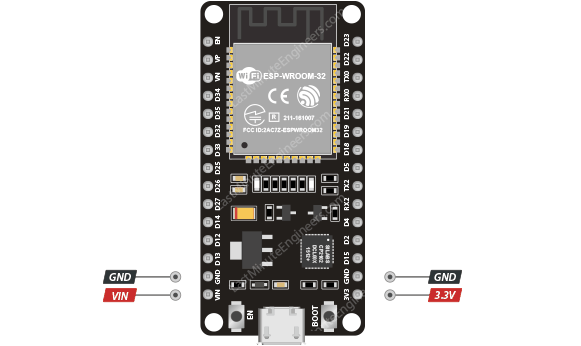 ESP32 Power Pins
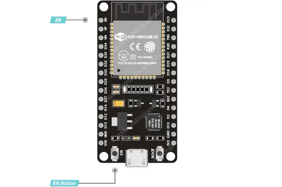 esp32 enable pin