 Custom Output from Alarm Clock Ceiling Projector © LGPL
My process for figuring out how to make the LED/LCD projector from an alarm
clock output whatever I want.
Custom Output from Alarm Clock Ceiling Projector © LGPL
My process for figuring out how to make the LED/LCD projector from an alarm
clock output whatever I want.
Components and supplies
Arduino Mega 2560 × 1
MS-CR1001 Alarm Clock × 1
Jumper wires (generic) × 5
Necessary tools and machines
Soldering iron (generic)
Or another way of joining two wires.
Multimeter
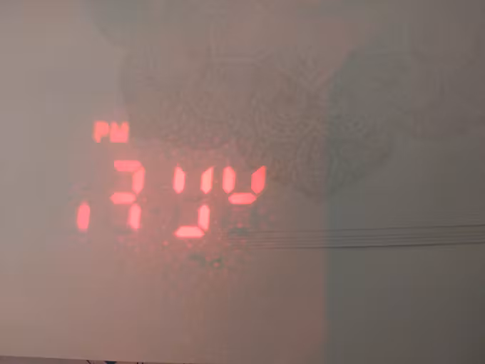
About this project In my quest to understand electronics better, I look for cheap or broken items to take apart. I found an alarm clock (model MS-CR1001) that projects the time onto the ceiling at a thrift store for seven bucks. I opened it up, saw that it was quite complicated, but thought I might be able to do something with the large LCD, the speaker, or the ceiling projector.
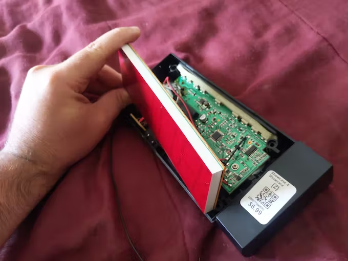 I thought being able to project custom data on the ceiling was the coolest
option, so I got started trying to figure it out.
I thought being able to project custom data on the ceiling was the coolest
option, so I got started trying to figure it out.

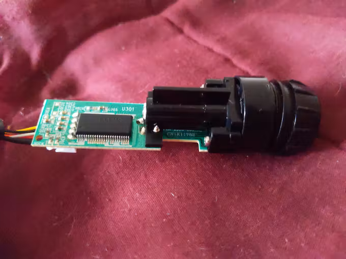 The projector is connected to the rest of the clock by five wires. I took off
the lens in front of the LED so that I could see the identifiers on the circuit
board more clearly. I tried searching the web for any of those identifiers, but
the only one I could find was a Chinese language datasheet for the big black
chip on the board (ET6621S).
The projector is connected to the rest of the clock by five wires. I took off
the lens in front of the LED so that I could see the identifiers on the circuit
board more clearly. I tried searching the web for any of those identifiers, but
the only one I could find was a Chinese language datasheet for the big black
chip on the board (ET6621S).
 I'm not really familiar with this kind of chip or how it works, and having the
datasheet in Chinese did not help things.
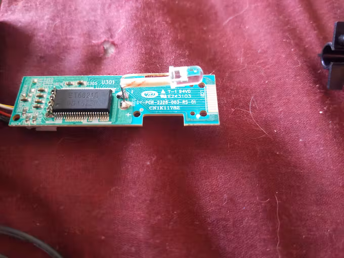
I was confused as well about how that LED projected anything at all. It's just
got two wires, like a normal LED. How is it making numbers?? I asked that
question on Reddit, and someone pointed out that what I thought was just a lens
in front of the LED was actually a lens *and* an LCD. It allows light through in
some parts and not others, depending on what needs to be projected. I hadn't
noticed that there are 12 little contacts at the end of the circuit board that
connect to that LCD.
After some time trying to figure it out and not really getting anywhere, I put
it aside for a while. A few weeks later, I asked for tips on how to use it on
the Arduino Device Hacking forum. Someone suggested that an oscilloscope or
logic analyzer would be very helpful in reading the signals going between the
clock and the projector circuit to understand how data is transmitted. I didn't
really have plans to buy those things for this little project.
Someone else went through the Chinese datasheet and tried to find hints as to
how the LCD driver chip works. That was helpful in pointing me in some of the
correct directions.
I had thought originally that this projected lots of little pixels so that I
could output anything I want, but after inspecting the LCD up close with it
still hooked up to the clock, I could see the time in tiny characters in the
middle, plus the faint image of the rest of the digit segments. So this LCD just
has four 7-segment digits, plus a colon in the middle and two PM's (the clock
allows you to flip the time upside down, so it needed a PM on top and one on
bottom).
I used a multimeter's continuity mode to determine which pins the five wires
connect to, by touching a wire terminal with one lead and touching each of the
many tiny pins on the chip with the other lead until I heard a beep.
I'm not really familiar with this kind of chip or how it works, and having the
datasheet in Chinese did not help things.
I was confused as well about how that LED projected anything at all. It's just
got two wires, like a normal LED. How is it making numbers?? I asked that
question on Reddit, and someone pointed out that what I thought was just a lens
in front of the LED was actually a lens *and* an LCD. It allows light through in
some parts and not others, depending on what needs to be projected. I hadn't
noticed that there are 12 little contacts at the end of the circuit board that
connect to that LCD.
After some time trying to figure it out and not really getting anywhere, I put
it aside for a while. A few weeks later, I asked for tips on how to use it on
the Arduino Device Hacking forum. Someone suggested that an oscilloscope or
logic analyzer would be very helpful in reading the signals going between the
clock and the projector circuit to understand how data is transmitted. I didn't
really have plans to buy those things for this little project.
Someone else went through the Chinese datasheet and tried to find hints as to
how the LCD driver chip works. That was helpful in pointing me in some of the
correct directions.
I had thought originally that this projected lots of little pixels so that I
could output anything I want, but after inspecting the LCD up close with it
still hooked up to the clock, I could see the time in tiny characters in the
middle, plus the faint image of the rest of the digit segments. So this LCD just
has four 7-segment digits, plus a colon in the middle and two PM's (the clock
allows you to flip the time upside down, so it needed a PM on top and one on
bottom).
I used a multimeter's continuity mode to determine which pins the five wires
connect to, by touching a wire terminal with one lead and touching each of the
many tiny pins on the chip with the other lead until I heard a beep.
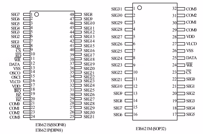 I used the datasheet to determine what the pins were called. I found that the
five wires were connected to VSS, VDD, CS, WR, and DATA. Someone else on the
Arduino forum posted a schematic they had found online that used this chip, and
the same five pins were being used.
Now, I know how to use a shift register, and after looking at the slightly more
understandable Google translated English version of the datasheet, I saw that
there was language I recognized, i.e. "latch", "clock", "data". Could it be that
it works the same way? Voltage, ground, latch, clock, and data pins?
I used the datasheet to determine what the pins were called. I found that the
five wires were connected to VSS, VDD, CS, WR, and DATA. Someone else on the
Arduino forum posted a schematic they had found online that used this chip, and
the same five pins were being used.
Now, I know how to use a shift register, and after looking at the slightly more
understandable Google translated English version of the datasheet, I saw that
there was language I recognized, i.e. "latch", "clock", "data". Could it be that
it works the same way? Voltage, ground, latch, clock, and data pins?
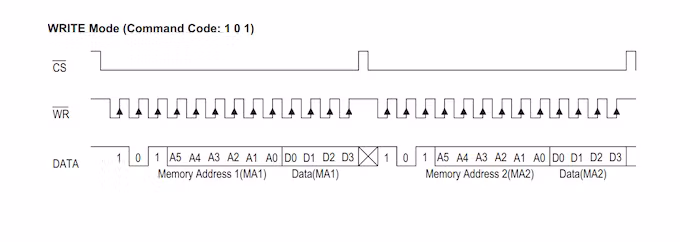
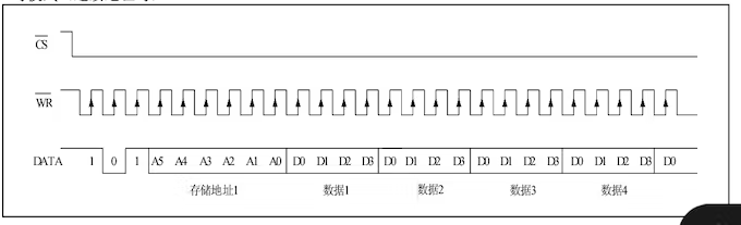 There were some timing diagrams, and this one looked promising. It looks like CS
is the latch pin, WR is the clock pin, and DATA is the data pin.
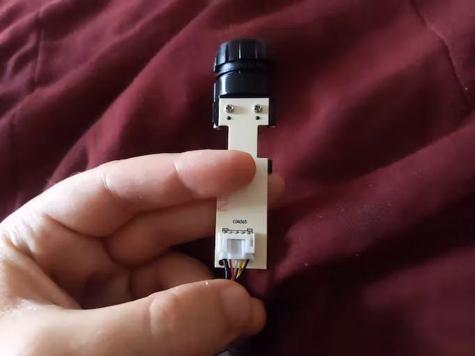
Before I started experimenting with sending it data, I had to figure out a way
to connect it to my Arduino. There's a little connector port on the projector
circuit, but I couldn't fit five Dupont wire connectors in there. So,
reluctantly, I cut the wires coming from the alarm clock to solder my own onto
them, so that I could still use the port connector.
There were some timing diagrams, and this one looked promising. It looks like CS
is the latch pin, WR is the clock pin, and DATA is the data pin.
Before I started experimenting with sending it data, I had to figure out a way
to connect it to my Arduino. There's a little connector port on the projector
circuit, but I couldn't fit five Dupont wire connectors in there. So,
reluctantly, I cut the wires coming from the alarm clock to solder my own onto
them, so that I could still use the port connector.
 Then I hooked up the five wires to the Arduino, and started the coding process.
I pulled up some basic shift register code, then edited it a bit to allow it to
send a custom number of bits, instead of the normal 8 bits, since the timing
diagram shows 26 bits.
/*F********************************************************************
*
**********************************************************************/
void
lcdShift( unsigned long data)
{ // ACCEPTS A BINARY NUMBER
int i; // DETERMINES LENGTH OF BINARY NUMBER
int len = (int)( log( data ) / log( 2 ) ) + 1;
// CREATES BINARY NMBR SAME LENGTH AS DATA, STARTING WITH 1
// FOLLOWED BY ALL 0'S. USED IN FOR LOOP
unsigned long bit = 1;
unsigned long chck = bit << (len -1 );
digitalWrite( latchPin, LOW );
// THIS LOOP GOES THROUGH BINARY NUMBER ONE BY ONE AND WRITES HIGH
//IF BIT IS 1 AND LOW IF BIT IS 0
for( i = 0; i < len; i++ )
{
digitalWrite( clkPin, LOW );
digitalWrite( dataPin, ((chck&(data << i)) == chck) ? HIGH : LOW);
// JUST FOR ME TO SEE THAT IT WAS SENDING RIGHT DATA TO CHIP
Serial.print( ((chck & (data << i)) == chck) ? HIGH : LOW);
delayMicroseconds( 10 );
digitalWrite( clkPin, HIGH );
delayMicroseconds( 10 );
}
digitalWrite( latchPin, HIGH );
Serial.println();
}
The datasheet also has a section with all sorts of commands, like LCD ON, LCD
OFF, BIAS 1/3, TONE 4k.
Then I hooked up the five wires to the Arduino, and started the coding process.
I pulled up some basic shift register code, then edited it a bit to allow it to
send a custom number of bits, instead of the normal 8 bits, since the timing
diagram shows 26 bits.
/*F********************************************************************
*
**********************************************************************/
void
lcdShift( unsigned long data)
{ // ACCEPTS A BINARY NUMBER
int i; // DETERMINES LENGTH OF BINARY NUMBER
int len = (int)( log( data ) / log( 2 ) ) + 1;
// CREATES BINARY NMBR SAME LENGTH AS DATA, STARTING WITH 1
// FOLLOWED BY ALL 0'S. USED IN FOR LOOP
unsigned long bit = 1;
unsigned long chck = bit << (len -1 );
digitalWrite( latchPin, LOW );
// THIS LOOP GOES THROUGH BINARY NUMBER ONE BY ONE AND WRITES HIGH
//IF BIT IS 1 AND LOW IF BIT IS 0
for( i = 0; i < len; i++ )
{
digitalWrite( clkPin, LOW );
digitalWrite( dataPin, ((chck&(data << i)) == chck) ? HIGH : LOW);
// JUST FOR ME TO SEE THAT IT WAS SENDING RIGHT DATA TO CHIP
Serial.print( ((chck & (data << i)) == chck) ? HIGH : LOW);
delayMicroseconds( 10 );
digitalWrite( clkPin, HIGH );
delayMicroseconds( 10 );
}
digitalWrite( latchPin, HIGH );
Serial.println();
}
The datasheet also has a section with all sorts of commands, like LCD ON, LCD
OFF, BIAS 1/3, TONE 4k.
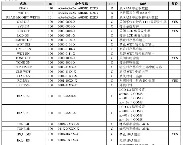 madmark2150, on the Arduino forum, deduced that those numbers after the words
are the binary commands that would be sent on the data line. The X's can be a 1
or a 0, it doesn't matter. He suggested I try the LCD ON/LCD OFF commands, as
well as all 1's, or alternating 1's and 0's in the "D" section of the Write
command, to see if anything happens. At this point, I was still using the 26
bits for the write command in the timing diagram, not realizing that it wasn't
exactly what I needed.
I wasn't getting any results from the Write command, but I found that if I sent
the LCD ON and LCD OFF commands, a single segment would flash on for a moment,
and I could see the faint outline of the rest of the segments.
Looking slightly promising...
It only flashed the segment if I alternated between LCD ON and LCD OFF, though.
Repeating the same command more than once did nothing. So it must actually be
getting the commands! Or it could at least tell that the 12 bits of data I was
sending differed by a single bit.
This really motivated me to keep trying to figure it out. I stayed up probably
way too late trying to decipher its secrets.
I copied all the commands from the datasheet into my code, so that I could
easily pass them into the lcdShift() function to send them to the chip.
unsigned long lcdOn = 0b100000000110;
unsigned long lcdOff = 0b100000000100;
unsigned long toneOn = 0b100000010010;
unsigned long toneOff = 0b100000010000;
unsigned long tone4k = 0b100010000000;
unsigned long tone2k = 0b100011000000;
unsigned long sysDis = 0b100000000000;
unsigned long sysEn = 0b100000000010;
unsigned long timerDis = 0b100000001000;
unsigned long timerEn = 0b100000001100;
unsigned long wdtDis = 0b100000001010;
unsigned long wdtEn = 0b100000001110;
unsigned long clrTimer = 0b100000011000;
unsigned long clrWdt = 0b100000011100;
unsigned long xtal32k = 0b100000101000;
unsigned long rc256k = 0b100000110000;
unsigned long ext256k = 0b100000111000;
unsigned long bias12x2 = 0b100001000000;
unsigned long bias12x3 = 0b100001001000;
unsigned long bias12x4 = 0b100001010000;
unsigned long bias13x2 = 0b100001000010;
unsigned long bias13x3 = 0b100001001010;
unsigned long bias13x4 = 0b100001010010;
unsigned long irqDis = 0b100100000000;
unsigned long irqEn = 0b100100010000;
unsigned long f1 = 0b100101000000;
unsigned long f2 = 0b100101000010;
unsigned long f4 = 0b100101000100;
unsigned long f8 = 0b100101000110;
unsigned long f16 = 0b100101001000;
unsigned long f32 = 0b100101001010;
unsigned long f64 = 0b100101001100;
unsigned long f128 = 0b100101001110;
unsigned long test = 0b100111000000;
unsigned long normal = 0b100111000110;
Then I just started trying random commands to see what did what. After some
trial and error, I found that if I used LCD ON, SYS EN, and XTAL32k (or RC256k),
then I would get some segments actually staying permanently lit! They weren't
numbers, it just looked like random segments.
madmark2150, on the Arduino forum, deduced that those numbers after the words
are the binary commands that would be sent on the data line. The X's can be a 1
or a 0, it doesn't matter. He suggested I try the LCD ON/LCD OFF commands, as
well as all 1's, or alternating 1's and 0's in the "D" section of the Write
command, to see if anything happens. At this point, I was still using the 26
bits for the write command in the timing diagram, not realizing that it wasn't
exactly what I needed.
I wasn't getting any results from the Write command, but I found that if I sent
the LCD ON and LCD OFF commands, a single segment would flash on for a moment,
and I could see the faint outline of the rest of the segments.
Looking slightly promising...
It only flashed the segment if I alternated between LCD ON and LCD OFF, though.
Repeating the same command more than once did nothing. So it must actually be
getting the commands! Or it could at least tell that the 12 bits of data I was
sending differed by a single bit.
This really motivated me to keep trying to figure it out. I stayed up probably
way too late trying to decipher its secrets.
I copied all the commands from the datasheet into my code, so that I could
easily pass them into the lcdShift() function to send them to the chip.
unsigned long lcdOn = 0b100000000110;
unsigned long lcdOff = 0b100000000100;
unsigned long toneOn = 0b100000010010;
unsigned long toneOff = 0b100000010000;
unsigned long tone4k = 0b100010000000;
unsigned long tone2k = 0b100011000000;
unsigned long sysDis = 0b100000000000;
unsigned long sysEn = 0b100000000010;
unsigned long timerDis = 0b100000001000;
unsigned long timerEn = 0b100000001100;
unsigned long wdtDis = 0b100000001010;
unsigned long wdtEn = 0b100000001110;
unsigned long clrTimer = 0b100000011000;
unsigned long clrWdt = 0b100000011100;
unsigned long xtal32k = 0b100000101000;
unsigned long rc256k = 0b100000110000;
unsigned long ext256k = 0b100000111000;
unsigned long bias12x2 = 0b100001000000;
unsigned long bias12x3 = 0b100001001000;
unsigned long bias12x4 = 0b100001010000;
unsigned long bias13x2 = 0b100001000010;
unsigned long bias13x3 = 0b100001001010;
unsigned long bias13x4 = 0b100001010010;
unsigned long irqDis = 0b100100000000;
unsigned long irqEn = 0b100100010000;
unsigned long f1 = 0b100101000000;
unsigned long f2 = 0b100101000010;
unsigned long f4 = 0b100101000100;
unsigned long f8 = 0b100101000110;
unsigned long f16 = 0b100101001000;
unsigned long f32 = 0b100101001010;
unsigned long f64 = 0b100101001100;
unsigned long f128 = 0b100101001110;
unsigned long test = 0b100111000000;
unsigned long normal = 0b100111000110;
Then I just started trying random commands to see what did what. After some
trial and error, I found that if I used LCD ON, SYS EN, and XTAL32k (or RC256k),
then I would get some segments actually staying permanently lit! They weren't
numbers, it just looked like random segments.
 Then I found that some of the "BIAS" commands seemed to change which segments
were lit up. Some of the "BIAS" commands would make some of the segments bright,
and the rest of them about half as bright, and none of them fully off. So I knew
that probably wasn't the right "BIAS".
I settled on the command for BIAS 1/3 with 4 COMS as working pretty well, even
though I didn't really know what it meant.
I started searching for similar chips ("LCD driver 32x4") that have datasheets
in English, to see if I could figure out how this Chinese one works. I found
some seemingly similar ones, and one that seemed almost identical in its
commands and pin structures (HT1620).
I also tried researching how LCD drivers work, and what BIAS and COMS mean. I
found a few good sites, especially this one.
With that new info, I realized that the way the WRITE command works is that the
first part of the command (after the 101 identifier that tells the chip you're
feeding it data) is the address of a section of the LCD, which connects to four
different COMS. Those four COMS correspond to each of four segments in that
address.
So basically, you have to send 101, which is the command for data, followed by
the address, which is a six-bit number, followed by four 1-bit numbers,
corresponding to the four COMS.
I realized that the timing diagram I was looking at before was to send
consecutive write commands, one after the other, without having to keep putting
I found the timing diagram I need in the similar HT1620 chip datasheet.
Then I found that some of the "BIAS" commands seemed to change which segments
were lit up. Some of the "BIAS" commands would make some of the segments bright,
and the rest of them about half as bright, and none of them fully off. So I knew
that probably wasn't the right "BIAS".
I settled on the command for BIAS 1/3 with 4 COMS as working pretty well, even
though I didn't really know what it meant.
I started searching for similar chips ("LCD driver 32x4") that have datasheets
in English, to see if I could figure out how this Chinese one works. I found
some seemingly similar ones, and one that seemed almost identical in its
commands and pin structures (HT1620).
I also tried researching how LCD drivers work, and what BIAS and COMS mean. I
found a few good sites, especially this one.
With that new info, I realized that the way the WRITE command works is that the
first part of the command (after the 101 identifier that tells the chip you're
feeding it data) is the address of a section of the LCD, which connects to four
different COMS. Those four COMS correspond to each of four segments in that
address.
So basically, you have to send 101, which is the command for data, followed by
the address, which is a six-bit number, followed by four 1-bit numbers,
corresponding to the four COMS.
I realized that the timing diagram I was looking at before was to send
consecutive write commands, one after the other, without having to keep putting
I found the timing diagram I need in the similar HT1620 chip datasheet.
 I started running code that would send a write command, wait half a second or
so, increment the address by one, then do it again and again. And I watched the
projector to see if anything interesting happened. I found that the addresses 0
through 23 (000000 through 010111 in the binary command) didn't do anything.
But 24 through 31 did. A few changed segments here and there, although I wasn't
sure of the pattern yet. But so close! I was altering segments semi-predictably!
And this matched up with the number of contacts between the circuit board and
the LCD. There are 12 contacts on the board, and I've got 8 addresses (24-31)
and 4 COMS that seem to be doing things to the LCD.
Then I started alternating sending commands that differed just by one bit in
the four 1-bit COM section. So I would send 101+011000+0000 then 101+011000+0001.
And I was getting a single segment to turn on and off! This command turned the
top segment of the fourth digit on and off.
If I alternated 101+011000+0000 and 101+011000+0010, then another segment would
turn on and off (the top right segment of the fourth digit).
If I alternated with more bits in the COM section changing, then more segments
would change. 101+011000+0000 and 101+011000+1110 would make three segments turn
on and off.
So each address controlled four different segments, each of which could be
turned on or off by setting each of the four COM bits to 1 or 0.
I started going through and copying down which segment was changed by each
address/COM combination. I found that address 24 corresponded to half of the
first digit, 25 to the other half, 26 to half of the second digit, and so on.
Here's the labeling system I used, to later use for constructing full digits or
letters (not all segments listed):
* colon 29x0001
* tl2 29x0010
* bl2 29x0100
* b2 29x1000
* t2 28x0001
* tr2 28x0010
* m2 28x0100
* br2 28x1000
* tl3 27x0010
* bl3 27x0100
* b3 27x1000
* t3 26x0001
* tr3 26x0010
* m3 26x0100
* br3 26x1000
* bpm 25x0001
* tl4 25x0010
* bl4 25x0100
* b4 25x1000
* t4 24x0001
* tr4 24x0010
* m4 24x0100
* br4 24x1000
For example, "tr4 24x0010" is the top right segment of the fourth digit. (I
ended up labeling them in reverse order. So 24 would be in the first digit, not
the fourth.) It is controlled by address 24 and the third COM bit.
(By the way, "segments" as used in the datasheets correspond to the part of the
LCD that are controlled by each address. So in this writeup, each "segment" as
used in the datasheets corresponds to four of the segments as I've been using
the word.)
I could now reliably turn on whichever segments I want. To make a "b" on the
second digit, I need two commands. One for the address for one half of the
second digit (101 011010 1111) and one for the other (101 011011 0010).
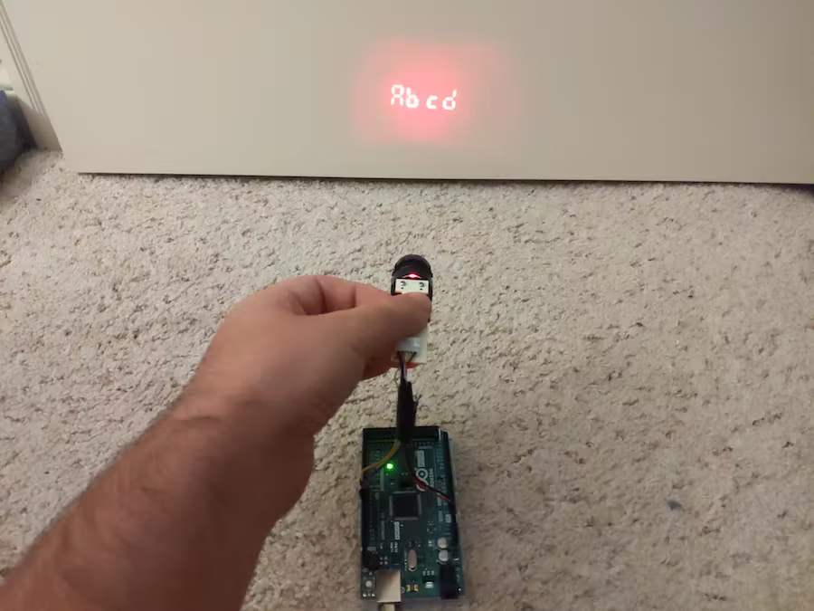
Then to make its debut onto the Arduino forum to tell the folks that I figured
it out, I made some code to display "A" on the first digit, wait a second, add
on "b" for the second digit, wait a second, add on "c" on the third, wait a
second, add a "d" on the fourth, wait a second, then clear everything in a sort
of swipe motion.
Brought to you from the bathroom.
madmark2150 gave me a lot of really good ideas for what to do with this
newfound power:
How about it showing FIRE and sounding an alarm if there is a hit on an IR
Sensor? You you can have it say "Door 3 Open" if there is an issue at night,
etc. It's a cool output device. I can think of lots of cute apps. Tie it in
with a SD card loaded with a story and have it read you (or your kids) to sleep.
Goose the LED power with a nice fat WHITE light LED (supply power
externally) and see if you can't make it ambient room light visible. Use a R/G/B
10mm LED and you can make it change color, Maybe with a BME280 for temp/humidity
/baro and have the temp show in color, red if hot, green if ok, blue if cold.
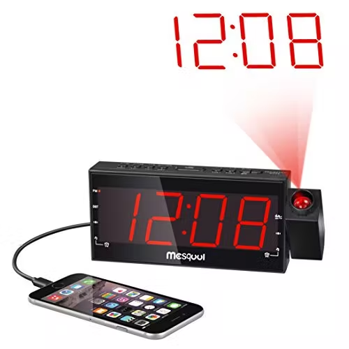
If you want to try this yourself with the same alarm clock, the model number is
MS-CR1001. I don't see any stores online that stock them, but eBay has some used
ones. You might find the right alarm clock if you just search "CR1001", but I'm
not sure. It should look like this:
I started running code that would send a write command, wait half a second or
so, increment the address by one, then do it again and again. And I watched the
projector to see if anything interesting happened. I found that the addresses 0
through 23 (000000 through 010111 in the binary command) didn't do anything.
But 24 through 31 did. A few changed segments here and there, although I wasn't
sure of the pattern yet. But so close! I was altering segments semi-predictably!
And this matched up with the number of contacts between the circuit board and
the LCD. There are 12 contacts on the board, and I've got 8 addresses (24-31)
and 4 COMS that seem to be doing things to the LCD.
Then I started alternating sending commands that differed just by one bit in
the four 1-bit COM section. So I would send 101+011000+0000 then 101+011000+0001.
And I was getting a single segment to turn on and off! This command turned the
top segment of the fourth digit on and off.
If I alternated 101+011000+0000 and 101+011000+0010, then another segment would
turn on and off (the top right segment of the fourth digit).
If I alternated with more bits in the COM section changing, then more segments
would change. 101+011000+0000 and 101+011000+1110 would make three segments turn
on and off.
So each address controlled four different segments, each of which could be
turned on or off by setting each of the four COM bits to 1 or 0.
I started going through and copying down which segment was changed by each
address/COM combination. I found that address 24 corresponded to half of the
first digit, 25 to the other half, 26 to half of the second digit, and so on.
Here's the labeling system I used, to later use for constructing full digits or
letters (not all segments listed):
* colon 29x0001
* tl2 29x0010
* bl2 29x0100
* b2 29x1000
* t2 28x0001
* tr2 28x0010
* m2 28x0100
* br2 28x1000
* tl3 27x0010
* bl3 27x0100
* b3 27x1000
* t3 26x0001
* tr3 26x0010
* m3 26x0100
* br3 26x1000
* bpm 25x0001
* tl4 25x0010
* bl4 25x0100
* b4 25x1000
* t4 24x0001
* tr4 24x0010
* m4 24x0100
* br4 24x1000
For example, "tr4 24x0010" is the top right segment of the fourth digit. (I
ended up labeling them in reverse order. So 24 would be in the first digit, not
the fourth.) It is controlled by address 24 and the third COM bit.
(By the way, "segments" as used in the datasheets correspond to the part of the
LCD that are controlled by each address. So in this writeup, each "segment" as
used in the datasheets corresponds to four of the segments as I've been using
the word.)
I could now reliably turn on whichever segments I want. To make a "b" on the
second digit, I need two commands. One for the address for one half of the
second digit (101 011010 1111) and one for the other (101 011011 0010).
Then to make its debut onto the Arduino forum to tell the folks that I figured
it out, I made some code to display "A" on the first digit, wait a second, add
on "b" for the second digit, wait a second, add on "c" on the third, wait a
second, add a "d" on the fourth, wait a second, then clear everything in a sort
of swipe motion.
Brought to you from the bathroom.
madmark2150 gave me a lot of really good ideas for what to do with this
newfound power:
How about it showing FIRE and sounding an alarm if there is a hit on an IR
Sensor? You you can have it say "Door 3 Open" if there is an issue at night,
etc. It's a cool output device. I can think of lots of cute apps. Tie it in
with a SD card loaded with a story and have it read you (or your kids) to sleep.
Goose the LED power with a nice fat WHITE light LED (supply power
externally) and see if you can't make it ambient room light visible. Use a R/G/B
10mm LED and you can make it change color, Maybe with a BME280 for temp/humidity
/baro and have the temp show in color, red if hot, green if ok, blue if cold.
If you want to try this yourself with the same alarm clock, the model number is
MS-CR1001. I don't see any stores online that stock them, but eBay has some used
ones. You might find the right alarm clock if you just search "CR1001", but I'm
not sure. It should look like this:
 Or try it with another brand if you want.
Let me know if you have any questions or any part of this wasn't clear.
(Update: Apparently, some identical alarm clock models use a different LCD
driver chip for the projector, and need slightly different code. Check the
comments to see how someone with a TM1621D driver got theirs working.)
Code
Make the projector cycle through A, b, c, d, then clear them allArduino
/*H********************************************************************
*
**********************************************************************/
int latchPin = 5; // WHITE
int clkPin = 6; // BLUE
int dataPin = 4; // YELLOW
//************************* DEFINES ************************************
#define BAUD 9600
//************************* PROTOTYPES ************************************
void lcdShift( unsigned long data);
void clearAll();
void clearDigit( int dig );
//************************* VARIABLES ************************************
unsigned long comWr = 0b101; // WRITE COMMAND CODE
unsigned long lcdOn = 0b100000000110; // ALL COMMANDS
unsigned long lcdOff = 0b100000000100;
unsigned long toneOn = 0b100000010010;
unsigned long toneOff = 0b100000010000;
unsigned long tone4k = 0b100010000000;
unsigned long tone2k = 0b100011000000;
unsigned long sysDis = 0b100000000000;
unsigned long sysEn = 0b100000000010;
unsigned long timerDis = 0b100000001000;
unsigned long timerEn = 0b100000001100;
unsigned long wdtDis = 0b100000001010;
unsigned long wdtEn = 0b100000001110;
unsigned long clrTimer = 0b100000011000;
unsigned long clrWdt = 0b100000011100;
unsigned long xtal32k = 0b100000101000;
unsigned long rc256k = 0b100000110000;
unsigned long ext256k = 0b100000111000;
unsigned long bias12x2 = 0b100001000000;
unsigned long bias12x3 = 0b100001001000;
unsigned long bias12x4 = 0b100001010000;
unsigned long bias13x2 = 0b100001000010;
unsigned long bias13x3 = 0b100001001010;
unsigned long bias13x4 = 0b100001010010;
unsigned long irqDis = 0b100100000000;
unsigned long irqEn = 0b100100010000;
unsigned long f1 = 0b100101000000;
unsigned long f2 = 0b100101000010;
unsigned long f4 = 0b100101000100;
unsigned long f8 = 0b100101000110;
unsigned long f16 = 0b100101001000;
unsigned long f32 = 0b100101001010;
unsigned long f64 = 0b100101001100;
unsigned long f128 = 0b100101001110;
unsigned long test = 0b100111000000;
unsigned long normal = 0b100111000110;
// SINCE EACH DIGIT IS COMPOSED OF TWO ADDRESSES, i HAVE EACH LETTER AS AN
// ARRAY OF TWO COM DESIGNATIONS. I WOULD DO THE SAME FOR THE NUMBERS 1-9 OR
// ANY OTHER SYMBOLS i WOULD NEED.
int a[2] = {0b1110, 0b1110};
int b[2] = {0b1111, 0b0010};
int c[2] = {0b0111, 0b0000};
int d[2] = {0b0111, 0b0110};
// A NESTED ARRAY FOR THE ADDRESSES FOR EACH DIGIT.
// FOR EXAMPLE DIGIT[1][0] WOULD GIVE YOU THE FIRST ADDRESS OF THE SECOND DIGIT.
// digit[1][1] WOULD GIVE YOU THE SECOND ADDRESS OF THE SECOND DIGIT.
int digit[4][2] = {{24, 25}, {26, 27}, {28, 29}, {30, 31}};
// TO MAKE AN "A", YOU WOULD SEND THESE TWO COMMANDS:
// lcdShift(comWr*1024 + digit[0][0]*16 + a[0]);
// lcdShift(comWr*1024 + digit[0][1]*16 + a[1]);
// THE *1024 AND *16 PUT THE COMMAND AND ADDRESS, RESPECTIVELY, IN THE CORRECT
// PLACE IN THE FINAL BINARY COMMAND.
// THE FIRST FUNCTION WOULD SEND THE BINARY NUMBER, 101 011000 1110 (WITHOUT THE
// SPACES).
/*F********************************************************************
*
**********************************************************************/
void
setup()
{
Serial.begin( BAUD );
pinMode( latchPin, OUTPUT );
pinMode( dataPin, OUTPUT );
pinMode( clkPin, OUTPUT );
lcdShift( normal ); // THE APPARENTLY NECESSARY COMMANDS
lcdShift( lcdOn );
lcdShift( xtal32k );
lcdShift( sysEn );
lcdShift( bias13x4 );
}
/*F********************************************************************
* LOOPS "Abcd"
**********************************************************************/
void
loop()
{
lcdShift( comWr * 1024 + digit[0][0] * 16 + a[0]);
lcdShift( comWr * 1024 + digit[0][1] * 16 + a[1]);
delay( 1000 );
lcdShift( comWr * 1024 + digit[1][0] * 16 + b[0]);
lcdShift( comWr * 1024 + digit[1][1] * 16 + b[1]);
delay( 1000 );
lcdShift( comWr * 1024 + digit[2][0] * 16 + c[0]);
lcdShift( comWr * 1024 + digit[2][1] * 16 + c[1]);
delay( 1000 );
lcdShift( comWr * 1024 + digit[3][0] * 16 + d[0]);
lcdShift( comWr * 1024 + digit[3][1] * 16 + d[1]);
delay( 1000 );
clearAll();
delay( 1000 );
/*
COM assignments for the different segments.
--Even addresses (24, 26, 28, 30)
bottom 0001
bottom left 0010
middle 0100
top left 1000
--Odd addresses (25, 27, 29, 31)
bottom right 0010
top right 0100
top 1000
--Other segments
colon 29x0001
top PM 31x0001
bottom PM 25x0001
*/
}
/*F********************************************************************
* SEND A DATA STREAM TO THE CHIP.
TAKES A BINARY NUMBER OF ANY LENGTH.
**********************************************************************/
void
lcdShift( unsigned long data)
{
unsigned long bit = 1;
int i;
int len = (int)(log( data ) / log( 2 )) +1;
unsigned long chck = bit << ( len -1);
digitalWrite( latchPin, LOW );
for( i = 0; i < len; i++)
{
digitalWrite( clkPin, LOW );
digitalWrite( dataPin,(( chck & (data << i)) == chck) ? HIGH : LOW);
delayMicroseconds( 10 );
digitalWrite( clkPin, HIGH );
delayMicroseconds( 10 );
}
digitalWrite( latchPin, HIGH );
}
/*F********************************************************************
* TURNS OFF ALL SEGMENTS
**********************************************************************/
void
clearAll()
{
long i;
for( i = 31; i > 23; i-- )
{
lcdShift( comWr * 1024 + i*16 + 0b0000 );
delay( 100 );
}
}
/*F********************************************************************
* TURNS OFF THE SEGMENTS OF A SINGLE DIGIT.
**********************************************************************/
void
clearDigit( int dig )
{
lcdShift( comWr * 1024 + digit[dig][0] * 16 + 0b0000);
lcdShift( comWr * 1024 + digit[dig][1] * 16 + 0b0000);
}
Or try it with another brand if you want.
Let me know if you have any questions or any part of this wasn't clear.
(Update: Apparently, some identical alarm clock models use a different LCD
driver chip for the projector, and need slightly different code. Check the
comments to see how someone with a TM1621D driver got theirs working.)
Code
Make the projector cycle through A, b, c, d, then clear them allArduino
/*H********************************************************************
*
**********************************************************************/
int latchPin = 5; // WHITE
int clkPin = 6; // BLUE
int dataPin = 4; // YELLOW
//************************* DEFINES ************************************
#define BAUD 9600
//************************* PROTOTYPES ************************************
void lcdShift( unsigned long data);
void clearAll();
void clearDigit( int dig );
//************************* VARIABLES ************************************
unsigned long comWr = 0b101; // WRITE COMMAND CODE
unsigned long lcdOn = 0b100000000110; // ALL COMMANDS
unsigned long lcdOff = 0b100000000100;
unsigned long toneOn = 0b100000010010;
unsigned long toneOff = 0b100000010000;
unsigned long tone4k = 0b100010000000;
unsigned long tone2k = 0b100011000000;
unsigned long sysDis = 0b100000000000;
unsigned long sysEn = 0b100000000010;
unsigned long timerDis = 0b100000001000;
unsigned long timerEn = 0b100000001100;
unsigned long wdtDis = 0b100000001010;
unsigned long wdtEn = 0b100000001110;
unsigned long clrTimer = 0b100000011000;
unsigned long clrWdt = 0b100000011100;
unsigned long xtal32k = 0b100000101000;
unsigned long rc256k = 0b100000110000;
unsigned long ext256k = 0b100000111000;
unsigned long bias12x2 = 0b100001000000;
unsigned long bias12x3 = 0b100001001000;
unsigned long bias12x4 = 0b100001010000;
unsigned long bias13x2 = 0b100001000010;
unsigned long bias13x3 = 0b100001001010;
unsigned long bias13x4 = 0b100001010010;
unsigned long irqDis = 0b100100000000;
unsigned long irqEn = 0b100100010000;
unsigned long f1 = 0b100101000000;
unsigned long f2 = 0b100101000010;
unsigned long f4 = 0b100101000100;
unsigned long f8 = 0b100101000110;
unsigned long f16 = 0b100101001000;
unsigned long f32 = 0b100101001010;
unsigned long f64 = 0b100101001100;
unsigned long f128 = 0b100101001110;
unsigned long test = 0b100111000000;
unsigned long normal = 0b100111000110;
// SINCE EACH DIGIT IS COMPOSED OF TWO ADDRESSES, i HAVE EACH LETTER AS AN
// ARRAY OF TWO COM DESIGNATIONS. I WOULD DO THE SAME FOR THE NUMBERS 1-9 OR
// ANY OTHER SYMBOLS i WOULD NEED.
int a[2] = {0b1110, 0b1110};
int b[2] = {0b1111, 0b0010};
int c[2] = {0b0111, 0b0000};
int d[2] = {0b0111, 0b0110};
// A NESTED ARRAY FOR THE ADDRESSES FOR EACH DIGIT.
// FOR EXAMPLE DIGIT[1][0] WOULD GIVE YOU THE FIRST ADDRESS OF THE SECOND DIGIT.
// digit[1][1] WOULD GIVE YOU THE SECOND ADDRESS OF THE SECOND DIGIT.
int digit[4][2] = {{24, 25}, {26, 27}, {28, 29}, {30, 31}};
// TO MAKE AN "A", YOU WOULD SEND THESE TWO COMMANDS:
// lcdShift(comWr*1024 + digit[0][0]*16 + a[0]);
// lcdShift(comWr*1024 + digit[0][1]*16 + a[1]);
// THE *1024 AND *16 PUT THE COMMAND AND ADDRESS, RESPECTIVELY, IN THE CORRECT
// PLACE IN THE FINAL BINARY COMMAND.
// THE FIRST FUNCTION WOULD SEND THE BINARY NUMBER, 101 011000 1110 (WITHOUT THE
// SPACES).
/*F********************************************************************
*
**********************************************************************/
void
setup()
{
Serial.begin( BAUD );
pinMode( latchPin, OUTPUT );
pinMode( dataPin, OUTPUT );
pinMode( clkPin, OUTPUT );
lcdShift( normal ); // THE APPARENTLY NECESSARY COMMANDS
lcdShift( lcdOn );
lcdShift( xtal32k );
lcdShift( sysEn );
lcdShift( bias13x4 );
}
/*F********************************************************************
* LOOPS "Abcd"
**********************************************************************/
void
loop()
{
lcdShift( comWr * 1024 + digit[0][0] * 16 + a[0]);
lcdShift( comWr * 1024 + digit[0][1] * 16 + a[1]);
delay( 1000 );
lcdShift( comWr * 1024 + digit[1][0] * 16 + b[0]);
lcdShift( comWr * 1024 + digit[1][1] * 16 + b[1]);
delay( 1000 );
lcdShift( comWr * 1024 + digit[2][0] * 16 + c[0]);
lcdShift( comWr * 1024 + digit[2][1] * 16 + c[1]);
delay( 1000 );
lcdShift( comWr * 1024 + digit[3][0] * 16 + d[0]);
lcdShift( comWr * 1024 + digit[3][1] * 16 + d[1]);
delay( 1000 );
clearAll();
delay( 1000 );
/*
COM assignments for the different segments.
--Even addresses (24, 26, 28, 30)
bottom 0001
bottom left 0010
middle 0100
top left 1000
--Odd addresses (25, 27, 29, 31)
bottom right 0010
top right 0100
top 1000
--Other segments
colon 29x0001
top PM 31x0001
bottom PM 25x0001
*/
}
/*F********************************************************************
* SEND A DATA STREAM TO THE CHIP.
TAKES A BINARY NUMBER OF ANY LENGTH.
**********************************************************************/
void
lcdShift( unsigned long data)
{
unsigned long bit = 1;
int i;
int len = (int)(log( data ) / log( 2 )) +1;
unsigned long chck = bit << ( len -1);
digitalWrite( latchPin, LOW );
for( i = 0; i < len; i++)
{
digitalWrite( clkPin, LOW );
digitalWrite( dataPin,(( chck & (data << i)) == chck) ? HIGH : LOW);
delayMicroseconds( 10 );
digitalWrite( clkPin, HIGH );
delayMicroseconds( 10 );
}
digitalWrite( latchPin, HIGH );
}
/*F********************************************************************
* TURNS OFF ALL SEGMENTS
**********************************************************************/
void
clearAll()
{
long i;
for( i = 31; i > 23; i-- )
{
lcdShift( comWr * 1024 + i*16 + 0b0000 );
delay( 100 );
}
}
/*F********************************************************************
* TURNS OFF THE SEGMENTS OF A SINGLE DIGIT.
**********************************************************************/
void
clearDigit( int dig )
{
lcdShift( comWr * 1024 + digit[dig][0] * 16 + 0b0000);
lcdShift( comWr * 1024 + digit[dig][1] * 16 + 0b0000);
}
Schematics
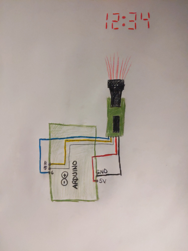 Wiring diagram
Where to connect the five wires from the circuit board to the Arduino
Schematic 40l8s5mqyq
Wiring diagram
Where to connect the five wires from the circuit board to the Arduino
Schematic 40l8s5mqyq