Sending Bytes to an 8x8 LED Matrix.
Programming 8x8 LED Matrix
Programming 8x8 LED Matrix
Sending Bytes to an 8x8 LED Matrix.
- 451,333 views
- 79 comments
- 360 respects
Components and supplies
|
| × | 16 | |||
|
| × | 2 | |||
_ztBMuBhMHo.avif)
|
| × | 1 | |||
| × | 1 | ||||
| × | 1 |
Apps and online services

|
|
About this project
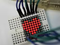
This is a very easy project for starters like me, the idea of it is to show you how to send bytes to an 8x8 LED matrix.
I have programmed this with all the letters of the alphabet,if you wish to add something go HERE: http://robojax.com/learn/arduino/8x8LED/
In that link you will be able to make more shapes.
In the left hand part of the page there will be an 8x8 matrix, with all the Leds off, by clicking them they will turn on and at the bottom of the page there will be the code that represents what you are doing to the matrix, when finished change the "sprite name " and paste the code that you just made, in the code that I made.
To make this project work you will need the library:
- FrequencyTimer2
Which you can download from:
Code
Here's the code Arduino
/*F********************************************************************
*
**********************************************************************/

//************************* DEFINES ************************************
#define ROW_1 2                              //update from SAnwandterg
#define ROW_2 3
#define ROW_3 4
#define ROW_4 5
#define ROW_5 6
#define ROW_6 7
#define ROW_7 8
#define ROW_8 9
#define COL_1 10
#define COL_2 11
#define COL_3 12
#define COL_4 13
#define COL_5 A0
#define COL_6 A1
#define COL_7 A2
#define COL_8 A3

//************************* PROTOTYPES ************************************
void  drawScreen( byte buffer2 []);

//************************* VARIABLES ************************************
const byte rows[] =
    { ROW_1, ROW_2, ROW_3, ROW_4, ROW_5, ROW_6, ROW_7, ROW_8 };
const byte col[] =
    { COL_1, COL_2, COL_3, COL_4, COL_5, COL_6, COL_7, COL_8 };

// display buffer It's prefilled with a smiling face (1 = ON, 0 = OFF)

byte ALL[] = { B11111111, B11111111, B11111111, B11111111
              , B11111111, B11111111, B11111111, B11111111 };
byte EX[] = { B00000000, B00010000, B00010000, B00010000
            , B00010000, B00000000, B00010000, B00000000 };
byte A[] = {  B00000000, B00111100, B01100110, B01100110
            , B01111110, B01100110, B01100110, B01100110 };
byte B[] = { B01111000, B01001000, B01001000, B01110000
            , B01001000, B01000100, B01000100, B01111100 };
byte C[] = { B00000000, B00011110, B00100000, B01000000
            , B01000000, B01000000, B00100000, B00011110 };
byte D[] = { B00000000, B00111000, B00100100, B00100010
            , B00100010, B00100100, B00111000, B00000000 };
byte E[] = { B00000000, B00111100, B00100000, B00111000
            , B00100000, B00100000, B00111100, B00000000 };
byte F[] = { B00000000, B00111100, B00100000, B00111000
            , B00100000, B00100000, B00100000, B00000000 };
byte G[] = { B00000000, B00111110, B00100000, B00100000
            , B00101110, B00100010, B00111110, B00000000 };
byte H[] = { B00000000, B00100100, B00100100, B00111100
            , B00100100, B00100100, B00100100, B00000000 };
byte I[] = { B00000000, B00111000, B00010000, B00010000
            , B00010000, B00010000, B00111000, B00000000 };
byte J[] = { B00000000, B00011100, B00001000, B00001000
            , B00001000, B00101000, B00111000, B00000000 };
byte K[] = { B00000000, B00100100, B00101000, B00110000
            , B00101000, B00100100, B00100100, B00000000 };
byte L[] = { B00000000, B00100000, B00100000, B00100000
            , B00100000, B00100000, B00111100, B00000000 };
byte M[] = { B00000000, B00000000, B01000100, B10101010
            , B10010010, B10000010, B10000010, B00000000 };
byte N[] = { B00000000, B00100010, B00110010, B00101010
            , B00100110, B00100010, B00000000, B00000000 };
byte O[] = { B00000000, B00111100, B01000010, B01000010
            , B01000010, B01000010, B00111100, B00000000 };
byte P[] = { B00000000, B00111000, B00100100, B00100100
            , B00111000, B00100000, B00100000, B00000000 };
byte Q[] = { B00000000, B00111100, B01000010, B01000010
            , B01000010, B01000110, B00111110, B00000001 };
byte R[] = { B00000000, B00111000, B00100100, B00100100
             , B00111000, B00100100, B00100100, B00000000 };
byte S[] = { B00000000, B00111100, B00100000, B00111100
            , B00000100, B00000100, B00111100, B00000000 };
byte T[] = { B00000000, B01111100, B00010000, B00010000
            , B00010000, B00010000, B00010000, B00000000 };
byte U[] = { B00000000, B01000010, B01000010, B01000010
            , B01000010, B00100100, B00011000, B00000000 };
byte V[] = { B00000000, B00100010, B00100010, B00100010
            , B00010100, B00010100, B00001000, B00000000 };
byte W[] = { B00000000, B10000010, B10010010, B01010100
            , B01010100, B00101000, B00000000, B00000000 };
byte X[] = { B00000000, B01000010, B00100100, B00011000
            , B00011000, B00100100, B01000010, B00000000 };
byte Y[] = { B00000000, B01000100, B00101000, B00010000
            , B00010000, B00010000, B00010000, B00000000 };
byte Z[] = { B00000000, B00111100, B00000100, B00001000
            , B00010000, B00100000, B00111100, B00000000 };
float timeCount = 0;

/*F********************************************************************
*
**********************************************************************/
void
setup()
{
    // Open serial port
    Serial.begin( 9600 );
    // Set all used pins to OUTPUT
    // very important! If pins are set to input display will be very dim.
    for( byte i = 2 ; i <= 13 ; i++ )
        pinMode( i, OUTPUT);
    pinMode( A0, OUTPUT);
    pinMode( A1, OUTPUT);
    pinMode ( A2, OUTPUT);
    pinMode ( A3, OUTPUT);
}
/*F********************************************************************
*
**********************************************************************/
void
loop()
{
    // could be rewritten to not use delay, which would make it appear brighter
    delay( 5 );
    timeCount += 1;
    if( timeCount < 20 )
        drawScreen( A );
    else if( timeCount < 40 )
        drawScreen( R );
    else if( timeCount < 60 )
            drawScreen( D );
    else if( timeCount < 80 )
        drawScreen( U );
    else if( timeCount < 100 )
        drawScreen( I );
    else if( timeCount < 120 )
        drawScreen( N );
    else if( timeCount < 140 )
        drawScreen( O );
    else if( timeCount < 160 )
        drawScreen( ALL );
    else if( timeCount < 180 )
        drawScreen( ALL );
    else
        timeCount = 0; // back to the start
}
/*F********************************************************************
*
**********************************************************************/
void
drawScreen( byte buffer2 [])
{
    // Turn on each row in series
    for( byte i = 0 ; i < 8 ; i++ )        // count next row
    {
        digitalWrite( rows[i], HIGH);    //initiate whole row
        for( byte a =0 ; a < 8 ; a++ )    // count next row
        { // if You set (~buffer2[i] >> a) then You will have positive
            digitalWrite( col[a], (buffer2[i] >> a) & 0x01); // init col
            delayMicroseconds( 100 ); // uncoment delay for display speed
            //delayMicroseconds( 1000 );
            //delay(1 0 );
            //delay( 100 );
            digitalWrite( col[a], 1 );      // reset whole column
        }
        digitalWrite( rows[i], LOW );     // reset whole row
        // otherwise last row will intersect with next row
    }
}
//
/********************************************************
SIPLEST RESEMPLATION HOW FOR LOOP IS WORKING WITH EACH ROW
    digitalWrite( COL_1, (~b >> 0) & 0x01); // Get 1st bit: 10000000
    digitalWrite( COL_2, (~b >> 1) & 0x01); // Get 2nd bit: 01000000
    digitalWrite( COL_3, (~b >> 2) & 0x01); // Get 3rd bit: 00100000
    digitalWrite( COL_4, (~b >> 3) & 0x01); // Get 4th bit: 00010000
    digitalWrite( COL_5, (~b >> 4) & 0x01); // Get 5th bit: 00001000
    digitalWrite( COL_6, (~b >> 5) & 0x01); // Get 6th bit: 00000100
    digitalWrite( COL_7, (~b >> 6) & 0x01); // Get 7th bit: 00000010
    digitalWrite( COL_8, (~b >> 7) & 0x01); // Get 8th bit: 00000001
}*******************************************************
*/
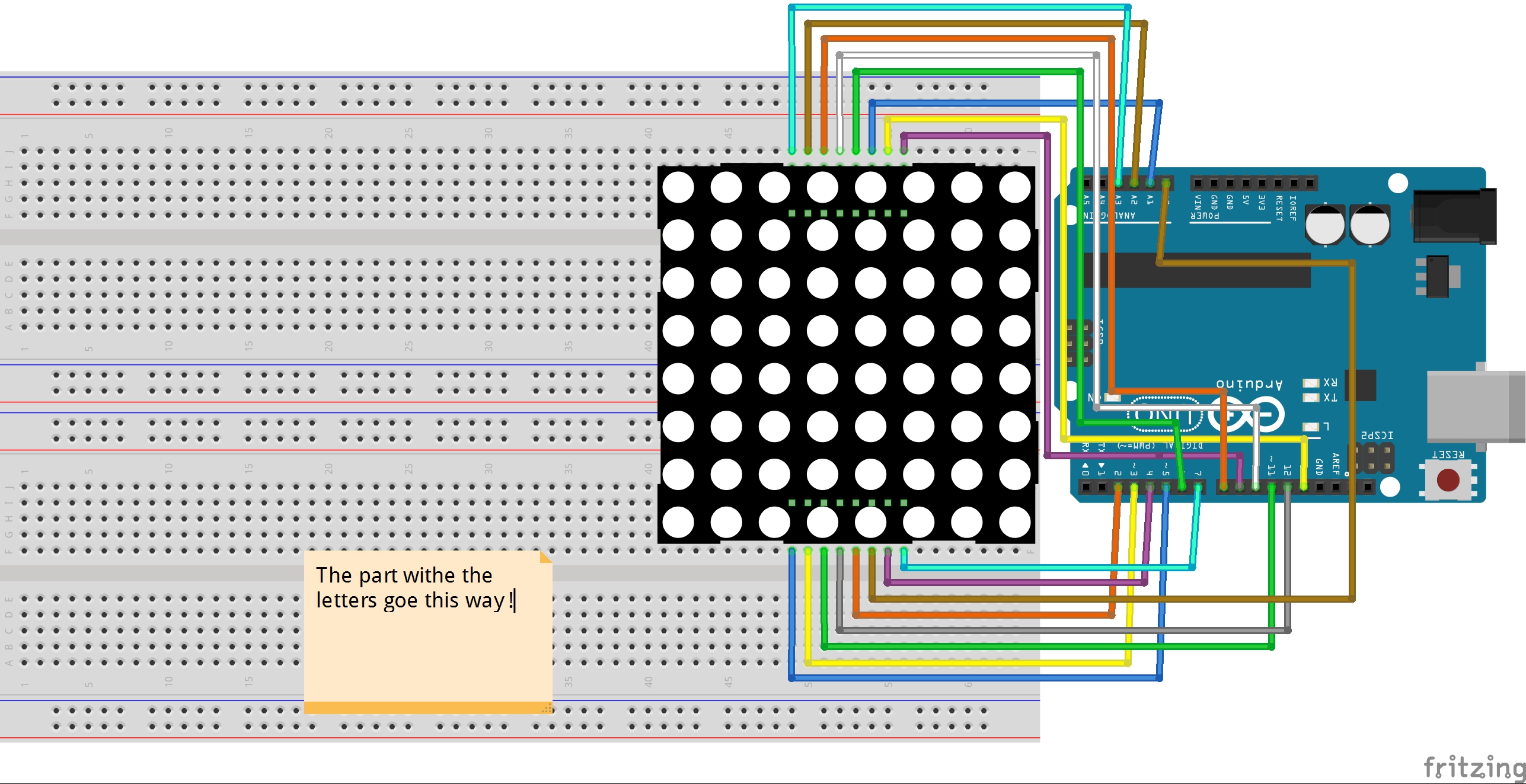
Schematics
Connections diagram
This is to make the connections easier