Getting Started With ESP32
From: https://electropeak.com/learn/getting-started-with-the
-esp32/
Communication, Programming
Getting Started with the ESP32 on Arduino IDE
Written by Mohammadreza Akbari
Overview
In this tutorial, you’ll get to know the ESP32 Wi–Fi and Bluetooth
module and how to set it up.
What You Will Learn
Introduction to the ESP32 and its applications
Installing the ESP32 on Arduino IDE
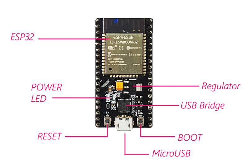
What is ESP32?
One of the most popular and practical modules of the past few years is the
ESP8266 Wi–Fi module. There are various versions of this module available
on the market. The ESP32 module is an upgraded version of the ESP8266. In
addition to the Wi-Fi module, this module also has a Bluetooth module of
version 4. Having dual-core CPU working in 80 to 240 MHz frequency, and
containing two Wi–Fi and Bluetooth modules and various input and output
pins, the ESP32 is an ideal choice to use in internet of things projects.
(IOT).
 The ESP32 Module Features
|
|
| Working Voltage | 2.2 to 3.6 volts
|
| Average Current | Around 80 mA
|
| Maximum Current | 500 mA
|
| Input/Output Pins | 32(The ESP32 chip has 48 I/O pin,s. But the module has
only 28 accessible pins.)
|
| ADC(Analog to Digital Converter) | 18 channels of 12 bits
|
| DAC(Digital to Analog Converter) | 2 channels of 8 bits
|
| UART(Serial Communication) | 3
|
| PWM | 32
|
| SPI Interface | 4
|
| I2C Interface | 2
|
| I2S Interface (to connect audio devices) | 2
|
| Capacitance TouchPads Pins | 10
|
| Memory Card Interface | 1
|
| CAN Interface | 1
|
| Temperature Sensor | 1
|
Note
You may not have access to some ESP32 chip pins in some modules.
The ESP32 Module Pinout
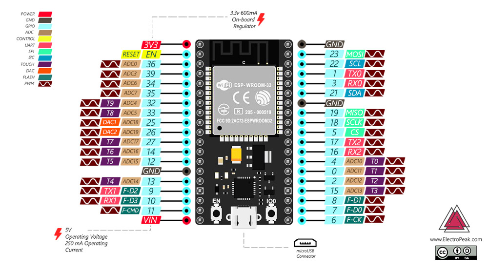 Although the ESP32 has fewer pins than commonly used processors, you won’t
face any problem with multiplexing multiple functions on a pin.
Warning
The voltage level of the ESP32 pins is 3.3 volts. If you want to connect
ESP32 to other devices that operate at 5–volts voltage, you should use a
level shifter to convert the voltage level.
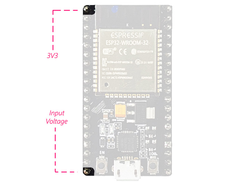
Supply Pins:
Although the ESP32 has fewer pins than commonly used processors, you won’t
face any problem with multiplexing multiple functions on a pin.
Warning
The voltage level of the ESP32 pins is 3.3 volts. If you want to connect
ESP32 to other devices that operate at 5–volts voltage, you should use a
level shifter to convert the voltage level.
Supply Pins:
The module has two 5V and 3.3V power supply pins. You can use these two pins
to supply other devices and modules.
 GND Pin:
 The module has 3 pins for its ground.
Enable Pin (EN):
The module has 3 pins for its ground.
Enable Pin (EN):
This pin is used to enable and disable the module. It should be HIGH to
enable the module and must be LOW to disable it.
Input/Output Pins (GPIO):
You can use the 32 GPIO pins to communicate with the LEDs, switches, and
other input/output devices.
You can pull-up or pull-down these pins internally.
Note
The GPIO6 to GPIO11 pins which are SCK / CLK, SDO / SD0, SDI / SD1, SHD /
SD2, SWP / SD3, and SCS / CMD pins, are used for SPI communication of the
internal flash memory of the module and we do not recommend you to use
them.
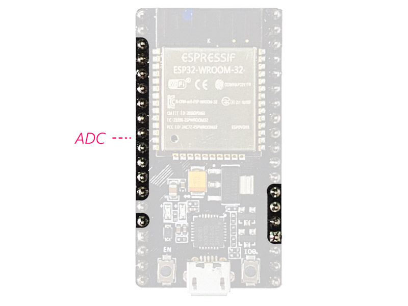
ADC:
You can use the 16 ADC pins on this module to convert analog voltages
(output of some sensors) to digital. Some of these converters are connected
to the internal amplifier and are able to measure small voltages with high
precision.
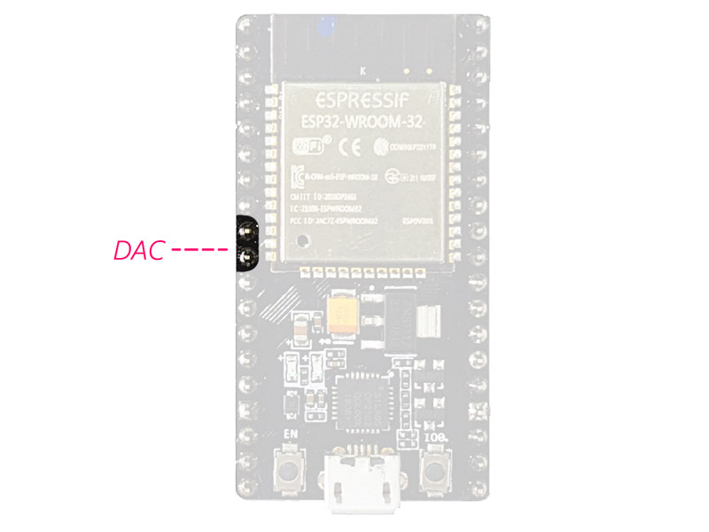
 DAC:
DAC:
The ESP32 module has two digital to analog converters with 8 bits accuracy.
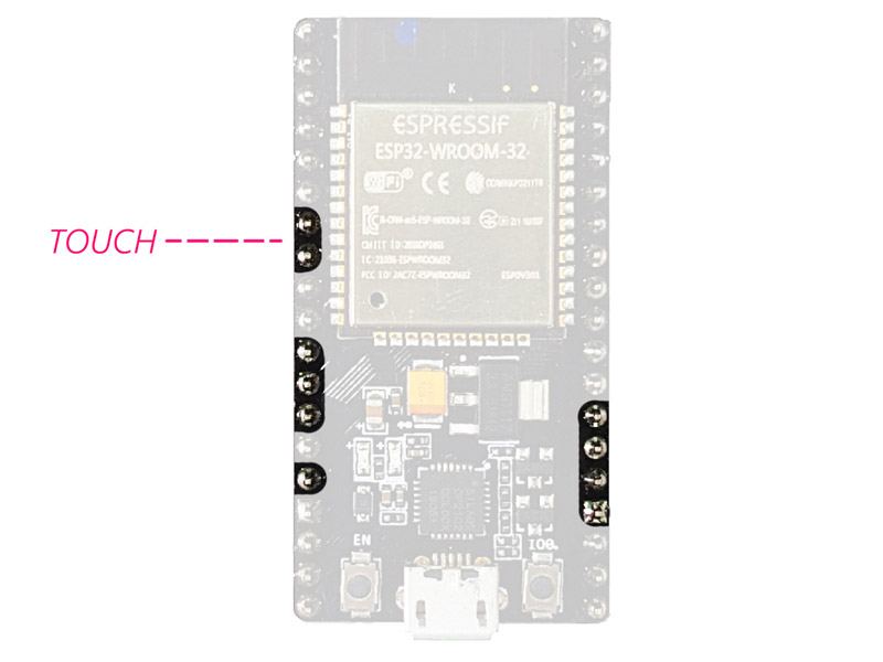
 Touchpads:
There are 10 pins on the ESP32 module that are sensitive to capacitor
changes. You can connect these pins to some pads (the pads on the PCB) and
use them as touch switches.
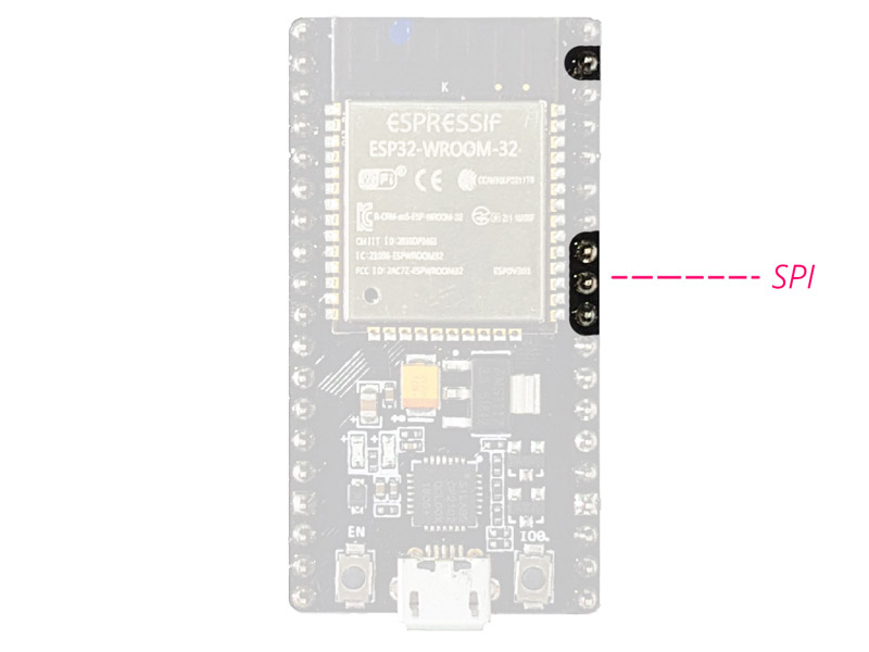
 SPI:
SPI:
There are two SPI interfaces on this module that you can use to connect the
display, the SD / microSD memory card module, external flash memory, and
more.
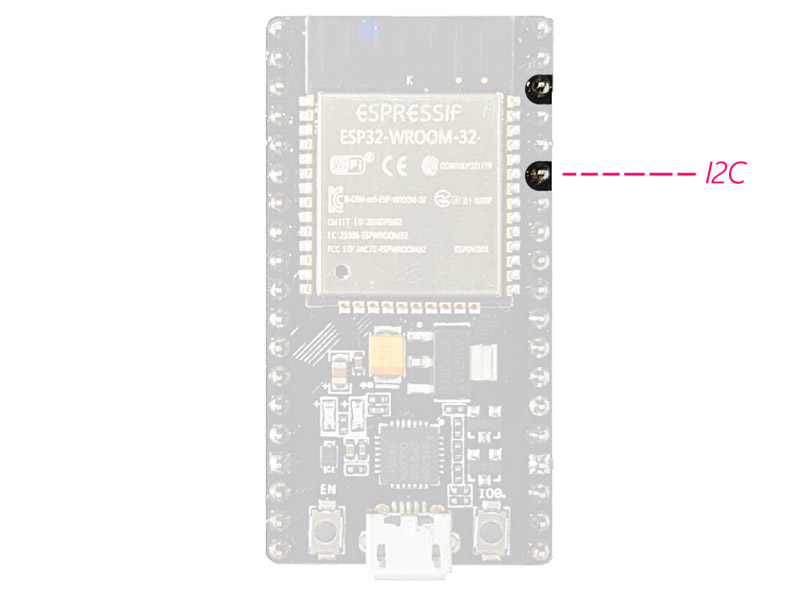
 I2C:
I2C:
SDA and SCL pins are used for I2C communication.
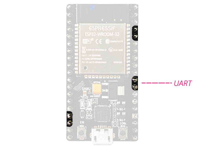
 Serial Communication (UART):
There are two UART serial interfaces on this module. Using these pins, you
can transfer information up to 5Mbps, between two devices. UART0 has also
CTS and RTS bases.
 PWM:
PWM:
Almost all of the ESP32 input/output pins can be used for PWM (Pulse Width
Modulation). Using these pins you can control the motors, LEDs light and
color and so on.
The ESP32 Module Modes
The ESP32 chip has 5 modes:
Active mode:
In this case, all parts of the Wi-Fi and Bluetooth transmitter and receiver
are active. In this case, the current consumption is between 80 and 260 mA.
Modem-sleep mode:
The processor is still active, but the Wi–Fi and Bluetooth are disabled.
The current consumption is between 3 and 20 mA, in this case.
Light-sleep mode:
The main processor stops working, but the RTC unit and the ULP processor
unit are still active. The current consumption is about 0.8 mA.
Deep-sleep mode:
Only the RTC unit is active. In this case, the data of Wi-Fi and Bluetooth
communications are stored in the RTC’s memory. The current consumption is
between 10 and 150 μA in this mode.
Hibernation mode:
All units are disabled, except for an RTC timer for the clock and some I / O
pins connected to the RTC. The RTC timer or the connected pins can wake the
chip up from this state. The current consumption is about 2.5 μA in this
case.
For more information, you can check the module datasheet.
ESP32 chip and Module Datasheet
The datasheet of ESP32 module and its chipset can be downloaded from the
following links.
- https://www.espressif.com/sites/default/files/docum
entation/esp32_datasheet_en.pdf
- https://espressif.com/sites/default/files/documentation/esp32-wroom
-32_datasheet_en.pdf
ESP32 VS. ESP8266
Various types of ESP32 and ESP8266 modules are available on the market. In
this part, the ESP8266 NodeMcu and ESP32 DEV modules are compared together:
| ESP8266 NodeMcu | ESP32 DEV Module
|
| Power | 3.3V | 3.3V
|
| CPU | Tensilica L106 32-bit | Xtensa® Dual-Core 32-bit LX6
|
| Bluetooth | Do not have | Compliant with Bluetooth v4.2 BR/EDR and BLE
specification
|
| GPIO | 17 | 32
|
| Flash size | Up to 16MB | Up to 16MB
|
| ADC | 10 bit | 12 bit
|
| DAC | Do not have | 2 * 8bit
|
| UART | 2 | 2
|
Usually, ESP32 modules are more expensive than ESP8266. So, if you do not
need Bluetooth, digital converter, many I / O pins, and …, you can save
your money by purchasing ESP8266 modules.
Required Materials
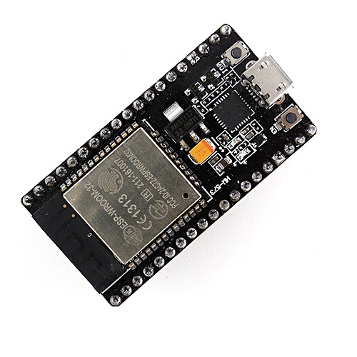 Hardware Components
ESp32 × 1
Software Apps
Arduino IDE
Installing the ESP32 on Arduino IDE
Hardware Components
ESp32 × 1
Software Apps
Arduino IDE
Installing the ESP32 on Arduino IDE
The installation process of ESP32 is almost the same as the ESP8266
installation. To install ESP32 on the Arduino IDE, do the following steps:
Note
You need Arduino IDE version 1.8.5 or higher to install the ESP32 on it.
First Step: Downloading the required files from the GitHub
Download the ESP32 Arduino Core from its GitHub account. You can use the
direct download link as well.
https://github.com/espressif/arduino-esp32/archive/master.zip
Second Step: Move the file to Arduino sketchbook location
The Arduino sketchbook is located in My Documents by default. To find the
exact path of your sketchbook, check the preferences from the File menu.
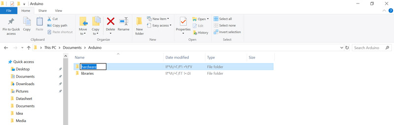
 Create a new folder named hardware next to the Arduino folder in your
sketchbook location.
Create a new folder named hardware next to the Arduino folder in your
sketchbook location.
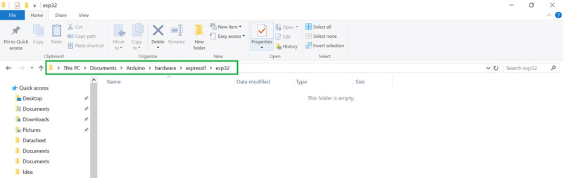
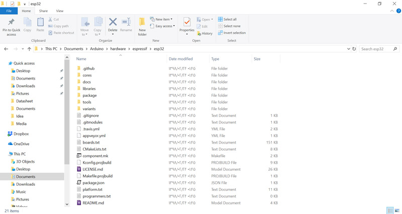
 Create a folder named espressif inside the hardware folder, then create
another folder named esp32 inside the espressif folder. Finally, the path
you created should be like the following picture:
Create a folder named espressif inside the hardware folder, then create
another folder named esp32 inside the espressif folder. Finally, the path
you created should be like the following picture:
 Extract the file you downloaded in the previous step and move it to this
address.
Extract the file you downloaded in the previous step and move it to this
address.
 Third Step: Run the get.exe
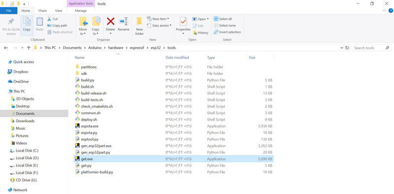
To install ESP32 on the Arduino software, you need to install the Xtensa GNU
compiler collection on your system. Go to esp32> tools and run the get.exe
file.
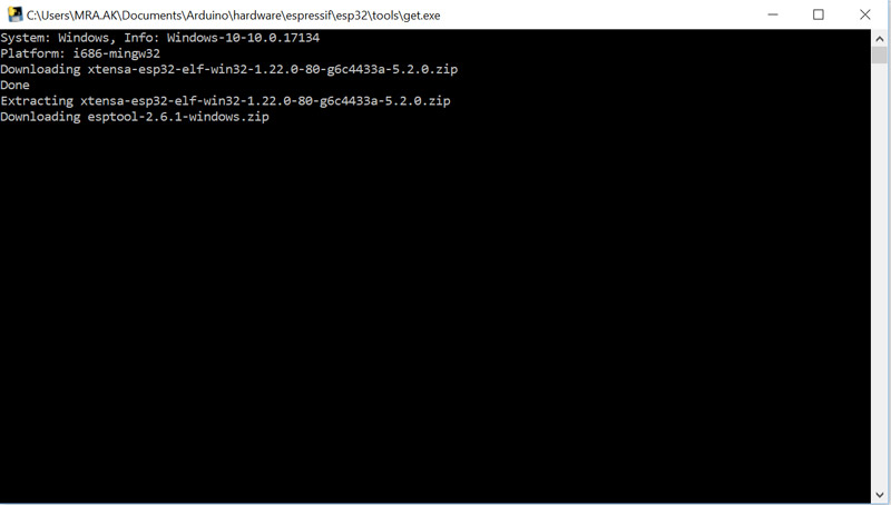
 After running the get.exe, the required files are automatically downloaded
and transferred to the tools folder. This step may take some time.
After running the get.exe, the required files are automatically downloaded
and transferred to the tools folder. This step may take some time.
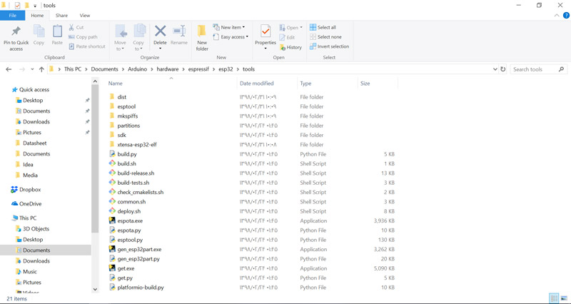
 After the installation is completed, new files must be added to the tools
folder.
After the installation is completed, new files must be added to the tools
folder.
 Uploading the Codes on ESP32 Using Arduino IDE
Uploading the codes on the ESP32 module is similar to other Arduino boards.
You can use Arduino built–in examples, like Blink, to test it.
Tip
If you did not install CP2102 driver in your computer before, you should
download it from here, then install it.
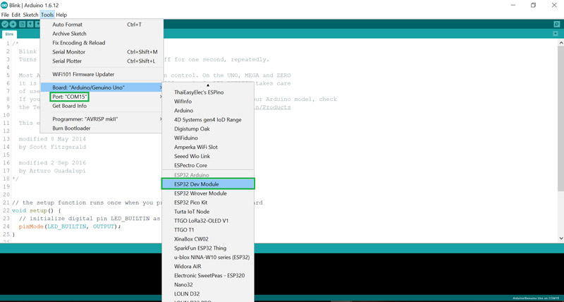
To upload your code, select the board type from the Tools menu. Then select
the port connected to your board and click on the upload.
 /*F************************************************
***************************
*
****************************************************
************************/
void
setup()
{
pinMode( 2, OUTPUT );
}
/*F*************************************************
**************************
*
****************************************************
************************/
void loop()
{
digitalWrite( 2, HIGH); // TURN LED ON (HIGH IS VOLTAGE LEVEL)
delay( 1000 ); // WAIT FOR A SECOND
digitalWrite( 2, LOW ); // TURN LED OFF BY MAKING VOLTAGE LOW
delay( 1000 ); // WAIT FOR A SECOND
}
Troubleshooting
/*F************************************************
***************************
*
****************************************************
************************/
void
setup()
{
pinMode( 2, OUTPUT );
}
/*F*************************************************
**************************
*
****************************************************
************************/
void loop()
{
digitalWrite( 2, HIGH); // TURN LED ON (HIGH IS VOLTAGE LEVEL)
delay( 1000 ); // WAIT FOR A SECOND
digitalWrite( 2, LOW ); // TURN LED OFF BY MAKING VOLTAGE LOW
delay( 1000 ); // WAIT FOR A SECOND
}
Troubleshooting
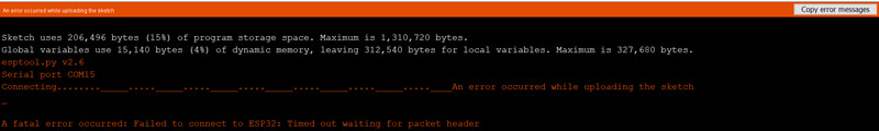
If you are faced with the following error, do not worry. This problem
usually occurs while programming the ESP32. Do the following steps to solve
the problem:
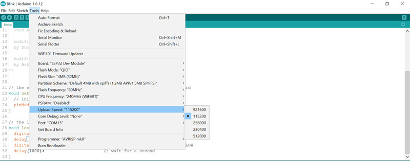
 Make sure the upload speed is set correctly. Usually, this speed should be
115200.
Make sure the upload speed is set correctly. Usually, this speed should be
115200.
 2.Press and hold the Boot button on your board.
3.Click on the Upload option.
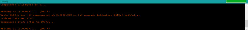
4.When you see the message Writing at 0x00001000 … (100%),
remove your finger from the Boot button.
2.Press and hold the Boot button on your board.
3.Click on the Upload option.
4.When you see the message Writing at 0x00001000 … (100%),
remove your finger from the Boot button.
 5.You must see the Done uploading message when the uploading is
finished.
5.You must see the Done uploading message when the uploading is
finished.
 What’s Next?
Create an HTTP page and control an LED through a webpage.
Control the LED using Bluetooth communication. (You can use Bluetooth
terminals to do this.)
PrevPreviousColor Recognition w/ TCS230 Sensor and Arduino [Calibration Code
included]