SmartConfig 6
#include <WiFi.h>
ESP32 Using SmartConfig
Changing Wi-Fi credentials in code for your ESP32 based IoT project is
frustrating, right?
As most of us, either hard code Wi-Fi credential or will use famous Wi-Fi manager.
Apart from this, there is a method known as ESP-Touch, and it works on
SmartConfig technology developed by TI.
We will explore SmartConfig technology, and you will be amazed as it is super
simple to use and lightweight.
We will be using Arduino IDE for programming ESP32.
 Project Summary
This tutorial will cover how to use the ESP-Touch protocol with your ESP32 based
IoT projects/devices.
Using ESP-Touch, you will no longer need to hard code Wi-Fi credentials as you
can easily change it whenever you want.
We will be using the Espressif app name as EspTouch: SmartConfig for ESP8266,
ESP32.
By using this app, we can easily configure our ESP32 device with a new Wi-Fi
credential.
Project Summary
This tutorial will cover how to use the ESP-Touch protocol with your ESP32 based
IoT projects/devices.
Using ESP-Touch, you will no longer need to hard code Wi-Fi credentials as you
can easily change it whenever you want.
We will be using the Espressif app name as EspTouch: SmartConfig for ESP8266,
ESP32.
By using this app, we can easily configure our ESP32 device with a new Wi-Fi
credential.
 ESP32 using Smart config using ESP-touch app flow chart
We will build an ESP32 project to store Wi-Fi credentials in EEPROM memory on a
successful configuration.
Additionally, we will use the onboard Boot button on ESP32 as a reset button for
erasing the stored Wi-Fi credentials and configuring a new one.
Here is the Tutorial breakdown:
Watch the Video Tutorial
About ESP-Touch Protocol.
Basic WiFiSmartConfig example.
Final WiFiSmartConfig project with storage and reset.
ESP32 using Smart config using ESP-touch app flow chart
We will build an ESP32 project to store Wi-Fi credentials in EEPROM memory on a
successful configuration.
Additionally, we will use the onboard Boot button on ESP32 as a reset button for
erasing the stored Wi-Fi credentials and configuring a new one.
Here is the Tutorial breakdown:
Watch the Video Tutorial
About ESP-Touch Protocol.
Basic WiFiSmartConfig example.
Final WiFiSmartConfig project with storage and reset.
Watch the Video Tutorial
This tutorial is available in video format (watch below) and written format
(continue reading this page).
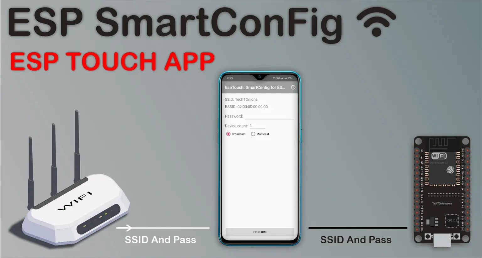
About ESP-Touch Protocol
ESP-Touch protocol uses a SmartConfig technology.
The SmartConfigTM is a technology developed by TI to connect a new Wi-Fi-based
IoT device to a Wi-Fi network.
It uses a mobile app to broadcast the network credentials from a smartphone, or
a tablet, to an un-provisioned Wi-Fi device.
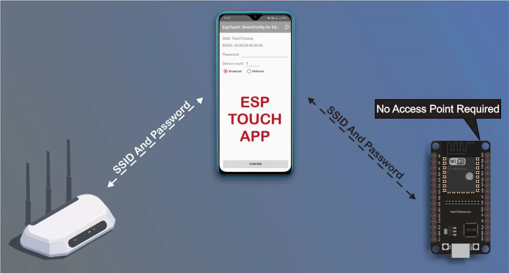
The major advantage of using ESP-Touch is that there is no need to create an
Access Point (AP) with a known SSID or Password in ESP32.
Therefore ESP-Touch protocol provides a seamless way to configure Wi-Fi devices
connecting to a router. It is very user-friendly when it comes to headless
systems. It only takes few clicks on your smartphone.
IoT device is not connected to the network initially, and the ESPTOUCH
application cannot send any information to the device directly. With the
ESP-TOUCH communication protocol, a device with Wi-Fi access capabilities, such
as a smartphone, can send a series of UDP packets to the Wi-Fi Access Point
(AP), encoding the SSID and password into the Length field of each of these UDP
packets. The IoT device can then reach the UDP packets, obtaining and parsing
out the required information. As per the ESP-Touch user guide, the data packet
structure looks like this.
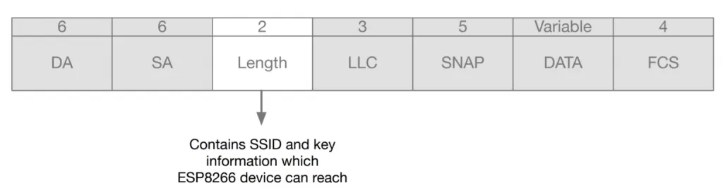 ESP touch data packet structure for smartconfig
And the protocol itself is lightweight compared to the Wi-Fi manager as the
Wi-Fi manager requires a webpage code to be stored on device memory.
ESP touch data packet structure for smartconfig
And the protocol itself is lightweight compared to the Wi-Fi manager as the
Wi-Fi manager requires a webpage code to be stored on device memory.
Prerequisites
We will use Arduino IDE for programming our ESP32 board.
If you are not familiar with Arduino IDE, then you can check our guide on
Skip the above steps if you have already done it before.
Additionally, we will need to download an Espressif app name as
Google EspTouch: SmartConfig for ESP8266, ESP32 for Android,
or Espressif Esptouch for apple.
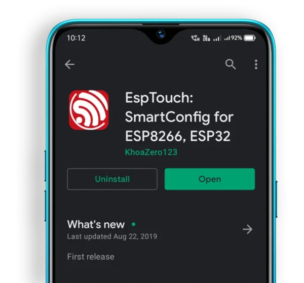 ESP Touch app download from play store on a android mobile
And if you are planning to develop your mobile application, then don’t worry as
Espressif has provided all support. Have a look at the following-
ESP Touch app download from play store on a android mobile
And if you are planning to develop your mobile application, then don’t worry as
Espressif has provided all support. Have a look at the following-
Basic WiFiSmartConfig example
ESP32 package comes with a basic WiFiSmartConfig example for us.
Let us understand this example first.
You can navigate to this example at
File > Examples > WiFi > WiFiSmartConfig.
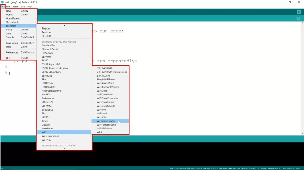 Arduino IDE opening ESP32 SmartConfig example code
Note:- The example path is only visible when selecting the proper ESP32 board in
Arduino IDE.
Here is the example code-
Arduino IDE opening ESP32 SmartConfig example code
Note:- The example path is only visible when selecting the proper ESP32 board in
Arduino IDE.
Here is the example code-
/*H********************************************************************
*
**********************************************************************/
#include "WiFi.h"
/*F********************************************************************
*
**********************************************************************/
void
setup()
{
Serial.begin( BAUD );
WiFi.mode( WIFI_AP_STA ); // INIT WiFi AS STATION, START SmartConfig
WiFi.beginSmartConfig();
Serial.println( "Waiting for SmartConfig." );
while( !WiFi.smartConfigDone() )// WAIT FOR SmartConfig PACKET FROM MOBILE
{
delay(500);
Serial.print( "." );
}
Serial.println( "" );
Serial.println( "SmartConfig received." );
Serial.println( "Waiting for WiFi" );
while( WiFi.status() != WL_CONNECTED) // WAIT FOR WiFi TO CONNECT TO AP
{
delay( 500 );
Serial.print( "." );
}
Serial.println( "WiFi Connected." );
Serial.print( "IP Address: " );
Serial.println( WiFi.localIP() );
}
/*F********************************************************************
*
**********************************************************************/
void
loop()
{
// put your main code here, to run repeatedly:
}
Upload this example code on your ESP32 board as we can see there is no
hard-coded network credential in the example.
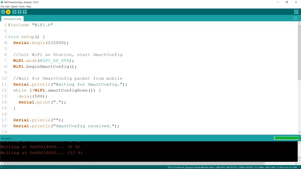 ESP32 SmartConfig default example code uploding
After uploading, open the serial monitor and set the appropriate baud rate.
You will see that it is waiting to be configured by SmartConfig, and it will be
showing continuous dots once it enters configuration mode.
ESP32 SmartConfig default example code uploding
After uploading, open the serial monitor and set the appropriate baud rate.
You will see that it is waiting to be configured by SmartConfig, and it will be
showing continuous dots once it enters configuration mode.
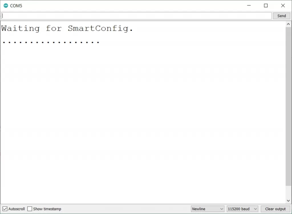 Arduino IDE serial monitor displays waiting for SamrtConfig configuration
Now open the ESP-Touch app in your mobile device and connect your mobile device
to your Wi-Fi router network. In android, it will also ask you to turn on
location service for detecting the connected Wi-Fi SSID.
Arduino IDE serial monitor displays waiting for SamrtConfig configuration
Now open the ESP-Touch app in your mobile device and connect your mobile device
to your Wi-Fi router network. In android, it will also ask you to turn on
location service for detecting the connected Wi-Fi SSID.
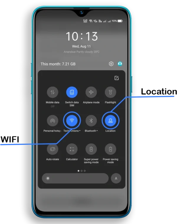 Android mobile turning on location service and connecting to Wi-Fi
It will fetch and display the connected Wi-Fi network SSID and BSSID.
Now you need to enter the password of the connected Wi-Fi network.
Android mobile turning on location service and connecting to Wi-Fi
It will fetch and display the connected Wi-Fi network SSID and BSSID.
Now you need to enter the password of the connected Wi-Fi network.
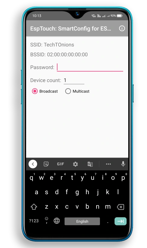 ESP Touch app entering Wi-Fi password and displaying connected network SSID and BSSID
Select the Multicast radio button.
ESP Touch app entering Wi-Fi password and displaying connected network SSID and BSSID
Select the Multicast radio button.
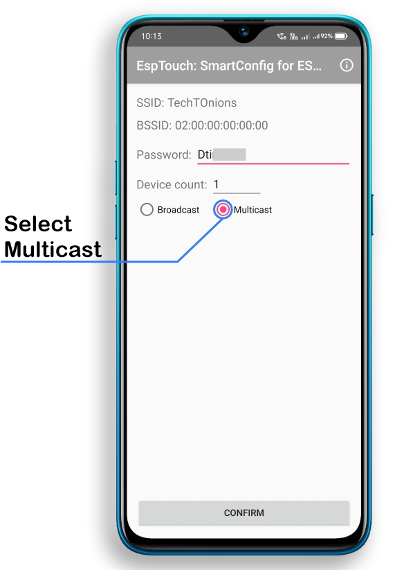 ESP-Touch app showing connected Wi-Fi SSID and BSSID. And selecting multicast option
And press the confirm button, you will see a popup like this.
ESP-Touch app showing connected Wi-Fi SSID and BSSID. And selecting multicast option
And press the confirm button, you will see a popup like this.
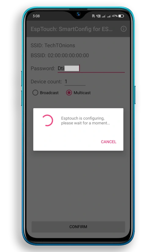 ESP-Touch app shows popup message of configuration
Wait for a while, and you will see a success message in the app along with the
connected ESP32 BSSID and Inet Address information.
ESP-Touch app shows popup message of configuration
Wait for a while, and you will see a success message in the app along with the
connected ESP32 BSSID and Inet Address information.
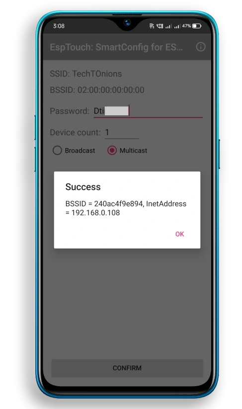 ESP-touch app showing success message
And, on the serial monitor, you will see a message as SmartConfig received, and
now it will be connected to the given Wi-Fi network.
ESP-touch app showing success message
And, on the serial monitor, you will see a message as SmartConfig received, and
now it will be connected to the given Wi-Fi network.
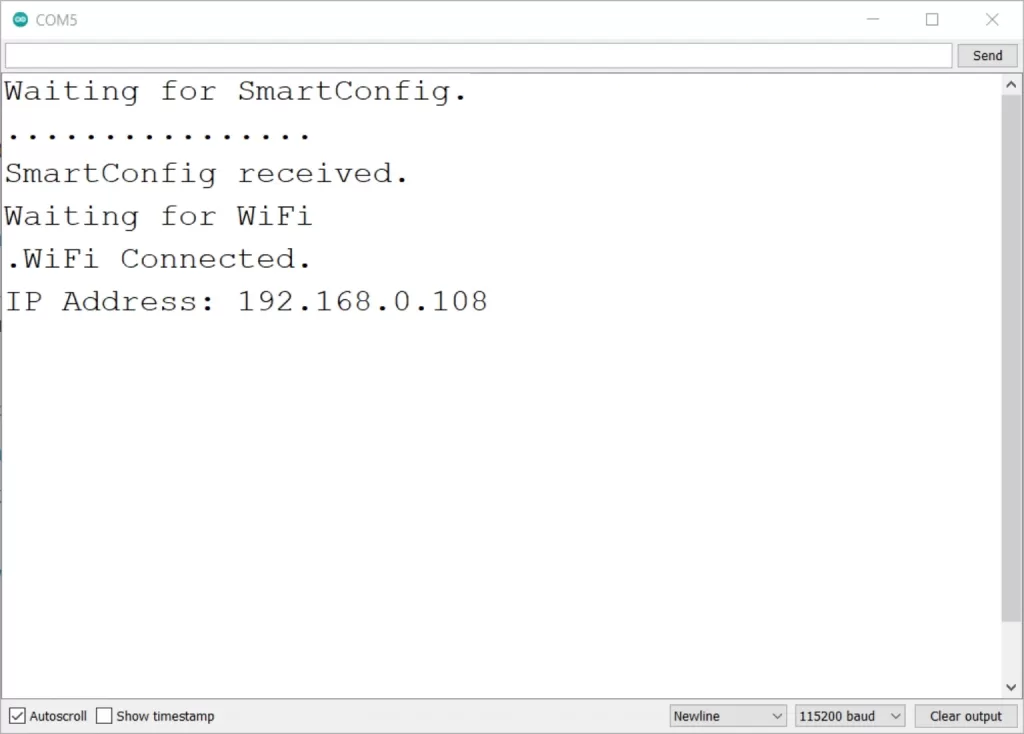 Arduino IDE serial monitor showing smartConfig data received and wifi connected
It’s that simple, and we do not need any stored SSID or Password for ESP Access
Point.
The example is not perfect to use right now, as we need to configure it whenever
we restart ESP because we are not storing Wi-Fi credentials. Also, ESP will
always enter in SmartConfig mode.
We will be modifying the existing code to overcome these issues.
Arduino IDE serial monitor showing smartConfig data received and wifi connected
It’s that simple, and we do not need any stored SSID or Password for ESP Access
Point.
The example is not perfect to use right now, as we need to configure it whenever
we restart ESP because we are not storing Wi-Fi credentials. Also, ESP will
always enter in SmartConfig mode.
We will be modifying the existing code to overcome these issues.
How code works
The first step will be to include a required library for the example.
WiFi.h library will take care of all wifi-related tasks like connecting to your
Wi-Fi and SmartConfig.
#include "WiFi.h"
setup() -1
Inside the setup function, we will first initialize serial communication to observe data in a serial monitor.
We are using the default baud rate of definition "BAUD" (#defned BAUD 9600). But you can change it if you want.
Serial.begin( BAUD );
Start SmartConfig
Before starting SmartConfig, it is mandatory to put ESP into station mode.
Therefore setting Wi-Fi mode as WIFI_AP_STA.
WiFi.mode( WIFI_AP_STA );
Now, turn ON SmartConfig by using this command.
WiFi.beginSmartConfig();
And now we will be wait in while the loop until SmartConfig data is received.
It means that it will stay in an infinite loop until someone configures it again
with a mobile app. Therefore, making it a drawback of this particular example.
You will see a continuous dot in the serial monitor when ESP enters in this
while loop.
while( !WiFi.smartConfigDone() )
{
delay( 500 );
Serial.print( "." );
}
Serial.println( "" );
Serial.println( "SmartConfig received." );
Once you successfully configure Wi-Fi credentials, it will automatically try to
connect to the given Wi-Fi credentials.
It will enter in another while loop until it gets connected to Wi-Fi.
Serial.println( "Waiting for WiFi" );
while( WiFi.status() != WL_CONNECTED )
{
delay( 500 );
Serial.print( "." );
}
After connection, we will be serial printing the Wi-Fi connected message along
with the IP address.
Serial.println( "WiFi Connected." );
Serial.print( "IP Address: " );
Serial.println( WiFi.localIP() );
Wala! It is that simple now; I can configure my ESP within 5 seconds.
WiFiConFig With Storage and Reset
Now, let us add a few more functionality to this example so that it becomes more
reliable.
In this project, we will store the received Wi-Fi credentials in EEPROM/Flash
memory. Therefore, we do not need to configure ESP every time.
Next, we will add a little check like when ESP turns ON; it will retrieve the
stored Wi-Fi credentials and connect to the Wi-Fi network.
If it connects successfully, then skip entering into SmartConfig mode.
Additionally, we will use the boot button as a reset button. It will clear the
stored Wi-Fi credentials and restart ESP for a new configuration.
You need to press and hold the boot button for more than 3 seconds and release
it, and you have successfully reset the configuration.
Here is the complete project code.
/*H*******************************************************
Date: 11-08-21 Code is written by: Dharmik
Configure ESP32 Wi-Fi parameters using SmartConfig
Find more on www.TechTOnions.com
********************************************************/
#include "WiFi.h"
#include "EEPROM.h"
//************************* DEFINES ************************************
#define LENGTH(x) (strlen(x) + 1) // LENGTH OF CHAR STRING
#define EEPROM_SIZE 200 // EEPROM SIZE
#define WIFI_RST 0 // WiFi CREDENTIAL RESET PIN (ESP32 Boot BUTTON)
typedef unsigned long ulong;
//************************* PROTOTYPES ************************************
void writeStringToFlash( const char* toStore, int startAddr );
String readStringFromFlash( int startAddr );
//************************* VARIABLES ************************************
String Ssid; // string variable to store Ssid
String Pwd; // string variable to store password
ulong RstMs;
/*F********************************************************************
*
**********************************************************************/
void
setup()
{
Serial.begin( BAUD ); // INIT SERIAL
pinMode( WIFI_RST, INPUT );
if( !EEPROM.begin( EEPROM_SIZE ) )
{ // INIT EEPROM
Serial.println( "failed to init EEPROM" );
delay( 1000 );
}
else
{
Ssid = readStringFromFlash( 0 ); // READ SSID STORED AT ADDRESS 0
Serial.print( "SSID = " );
Serial.println( Ssid );
Pwd = readStringFromFlash( 40 );// READ PASSWORD STORED AT ADDRESS 40
Serial.print( "Pwds = " );
Serial.println( Pwd );
}
WiFi.begin( Ssid.c_str(), Pwd.c_str() );
delay( 3500 ); // WAIT FOR A WHILE TILL ESP CONNECTS TO WiFi
if( WiFi.status() != WL_CONNECTED ) // IF WiFi NOT CONNECTED
{
WiFi.mode( WIFI_AP_STA ); // INIT WiFi AS STATION, START SmartConfig
WiFi.beginSmartConfig();
// WAIT FOR SmartConfig PACKET FROM MOBILE
Serial.println( "Waiting for SmartConfig." );
while( !WiFi.smartConfigDone())
{
delay( 500 );
Serial.print( "." );
}
Serial.println( "" );
Serial.println( "SmartConfig received." );
Serial.println( "Waiting for WiFi" );
while( WiFi.status() != WL_CONNECTED )// WAIT FOR WiFi CONNECT TO AP
{
delay( 500 );
Serial.print( "." );
}
Serial.println( "WiFi Connected." );
Serial.print( "IP Address: " );
Serial.println( WiFi.localIP() );
Ssid = WiFi.SSID(); // READ CONNECTED WiFi SSID AND PASSWORD
Pwd = WiFi.psk();
Serial.print( "SSID:" );
Serial.println( Ssid );
Serial.print( "Pss:" );
Serial.println( Pwd );
Serial.println( "Store SSID & Pwd in Flash");
writeStringToFlash( Ssid.c_str(), 0 ); // STORING SSID AT ADDRESS 0
writeStringToFlash( Pwd.c_str(), 40 ); // STORING PWD AT ADDRESS 40
}
else
Serial.println( "WiFi Connected" );
}
/*F********************************************************************
*
**********************************************************************/
void
loop()
{ // PUT YOUR MAIN CODE HERE, TO RUN REPEATEDLY
RstMs = millis();
while( digitalRead( WIFI_RST ) == LOW )
{
// Wait till boot button is pressed
}
// CHECK BUTTON PRESS TIME IF ITS > 3SEC RST WIFI CRED AND RESTART ESP
if( millis() - RstMs >= 3000 )
{
Serial.println( "Reseting WiFi credentials" );
writeStringToFlash( "", 0 ); // RESET SSID
writeStringToFlash( "", 40 ); // RESET PASSWORD
Serial.println( "Wifi credentials erased" );
Serial.println( "Restarting the ESP" );
delay( 500 );
ESP.restart(); // Restart ESP
}
}
/*F********************************************************************
*
**********************************************************************/
void
writeStringToFlash( const char *toStore, int startAddr )
{
int ndx = 0;
for( ; ndx < LENGTH( toStore ); ndx++ )
EEPROM.write( startAddr + ndx, toStore[ndx]);
EEPROM.write( startAddr + ndx, '\0' );
EEPROM.commit();
}
/*F********************************************************************
*
**********************************************************************/
String
readStringFromFlash( int startAddr )
{
int ndx = 0;
char in[128]; // CHAR ARRAY OF SIZE 128 FOR READING STORED DATA
for( ; ndx < 128; ndx++ )
in[ndx] = EEPROM.read( startAddr + ndx );
return String( in ); // CONVERT INPUT BUFF TO A STRING & RETURN
}
How Code Works
First, we will include all necessary libraries for this project.
WiFi.h library will take care of all wifi-related tasks like connecting to your Wi-Fi and SmartConfig.
EEPROM.h library will need to store data to EEPROM/Flash memory of ESP32.
#include "WiFi.h"
#include "EEPROM.h"
Defining custom function LENGTH(x) will give us a length of a char string with
one incremental. We will use this function later.
And define the EEPROM size required as EEPROM_SIZE.
#define LENGTH(x) (strlen(x) + 1) // length of char string
#define EEPROM_SIZE 200 // EEPROM size
We are using the Boot button of the ESP32 board for resetting the Wi-Fi
credential settings. The boot button on the ESP32 board is connected with a
GPIO0 pin and has a pullup resistor.
Therefore we will define WIFI_RST as 0. If you use any other pin for the reset
button, you need to add that GPIO number to the WIFI_RST variable.
#define WIFI_RST 0 //WiFi credential reset pin (Boot button on ESP32)
We are defining String variables for retrieving SSID and Password.
Additionally, we will use the rst_millis variable for counting how long the
reset button is pressed.
String Ssid; // STRING VARIABLE TO STORE SSID
String Pwd; // STRING VARIABLE TO STORE PASSWORD
unsigned long rst_millis;
setup()
We will initialize the serial communication with desired baud rate.
Serial.begin( BAUD ); // Init serial
Set the WIFI_RST pin as an input pin.
pinMode( WIFI_RST, INPUT );
Now, initialize the EEPROM with pre-defined EEPROM_SIZE.
Once it is initialized, we will read the stored SSID and Passwort as a String at addresses 0 and 40, respectively.
We use a user-defined function named as readStringFromFlash() for reading a string from EEPROM/flash memory.
if( !EEPROM.begin( EEPROM_SIZE ) )
{ //Init EEPROM
Serial.println( "failed to init EEPROM" );
delay( 1000 );
}
else
{
ssid = readStringFromFlash(0); // Read SSID stored at address 0
Serial.print("SSID = ");
Serial.println( Ssid );
Pwd = readStringFromFlash(40); // Read Password stored at address 40
Serial.print("Pwd = ");
Serial.println( Pwd );
}
Using Wi-Fi.begin function for connecting to the Wi-Fi network. We are passing
Wi-Fi credentials as a String variable; therefore, we will need to use c_str(),
which will returns a const char* that points to a null-terminated string.
We will add a slight delay so that ESP can connect to the Wi-Fi network.
WiFi.begin(ssid.c_str(), pss.c_str());
delay(3500); // Wait for a while till ESP connects to WiFi
After that delay, we will check that ESP32 is connected to Wi-Fi or not.
If ESP connects to Wi-Fi, then we will skip the SmartConfig code inside the if
condition.
And if it fails to connect with the Wi-Fi, we will init the Wi-Fi Station mode
and SmartConfig similarly done in previous example.
if( WiFi.status() != WL_CONNECTED ) // if WiFi is not connected
{ //Init WiFi as Station, start SmartConfig
WiFi.mode( WIFI_AP_STA );
WiFi.beginSmartConfig();
Wait for SmartConfig data to be arrived with while loop. Once network
credentials have arrived, it will try to connect to that Wi-Fi network.
// WAIT FOR sMARTcONFIG PACKET FROM MOBILE
Serial.println( "Waiting for SmartConfig.");
while( !WiFi.smartConfigDone() )
{
delay( 500 );
Serial.print( "." );
}
Serial.println( "" );
Serial.println( "SmartConfig received." );
//Wait for WiFi to connect to AP
Serial.println( "Waiting for WiFi");
while( WiFi.status() != WL_CONNECTED)
{
delay( 500 );
Serial.print( "." );
}
Serial.println("WiFi Connected.");
Serial.print("IP Address: ");
Serial.println(WiFi.localIP());
After Wi-Fi is connected, we will read the connected Wi-Fi SSID and password
with the following function.
ssid = WiFi.SSID();
pss = WiFi.psk();
Serial.print( "SSID:" );
Serial.println( ssid );
Serial.print( "PSS:" );
Serial.println( pss );
And we will store the new credentials by using another user-defined function,
writeStringToFlash(). We only need to pass string data along with an address.
Serial.println("Store SSID & PSS in Flash");
writeStringToFlash(ssid.c_str(), 0); // storing ssid at address 0
writeStringToFlash(pss.c_str(), 40); // storing pss at address 40
Loop()
Inside the loop function, we will store the current millis() value in the
rst_millis variable as we will use this value as a start time when someone
presses the Wi-Fi reset button.
rst_millis = millis();
When we press the Boot button, the while loop condition is satisfied. Hence, the
code is stuck inside the loop until the button is released.
while( digitalRead( WIFI_RST ) == LOW )
{
// Wait till boot button is pressed
}
When the button is released immediately, we will check how much time we have
pressed the button if time is greater than 3000mS, the if condition is satisfied.
if (millis() - rst_millis >= 3000)
Now we will erase the stored Wi-Fi credentials at addresses 0 and 40 by passing
blank values to the writeStringToFlash() function.
Serial.println( "Reseting the WiFi credentials" );
writeStringToFlash( "", 0 ); // RESET SSID
writeStringToFlash( "", 40 ); // RESET PASSWORD
Serial.println( "Wifi credentials erased");
And finally, we will trigger a software reset to the ESP32 with the following
command.
Serial.println( "Restarting the ESP");
delay( 500 );
ESP.restart(); // Restart ESP
writeStringToFlash( const char* toStore, int startAddr )
This user-defined function stores string or character array pointer in
EEPROM/Flash storage of ESP32.
We need to store it in non-volatile memory; hence data stored is not erased
even after power is OFF.
If we look closely at the code of this function, it is simply a for loop. It is
executed as per the LENGTH() function input, and as discussed earlier, it will
provide the length of a character string.
And we will use EEPROM.write() function to store each byte of character string
to a particular address passed and address keep incremented.
Once for loop is executed, we will save a '\0' as a string termination. And will
commit the changes so that it stores them all in memory.
void writeStringToFlash( const char* toStore, int startAddr)
{
int ndx = 0;
for( ; ndx < LENGTH( toStore) ; ndx++ )
EEPROM.write( startAddr + ndx, toStore[ndx] );
EEPROM.write( startAddr + ndx, '\0');
EEPROM.commit();
}
String readStringFromFlash(int startAddr)
This user-defined function reads stored character strings from the desired
address in EEPROM/Flash memory.
Here we are initializing the char array name as in[128] its size is 128, which
means it can only handle the string length lower than 128. you can increase the
size if you need to deal with bigger strings.
Similar to storing function, it also works with a for loop. It will read all
char byte one by one from the startAddr (start address).
And lastly, we will return it in the form of a String.
String
readStringFromFlash( int startAddr )
{
char in[128]; // CHAR ARRAY OF SIZE 128 FOR READING STORED DATA
int ndx = 0;
for( ; ndx < 128; ndx++ )
in[ndx] = EEPROM.read( startAddr + ndx );
return String( in );
}
Wrapping Up
We have seen that SmartConfig is a very efficient and straightforward way to
configure network credentials in our ESP32 based IoT projects or devices.
And for configuration, ESP32 does not need any connected Wi-Fi network as the
Wi-Fi manager requires.
We have tested SmartConfig with a standard Wi-Fi router, and it worked like a
charm.
We have also tried this method using a mobile hotspot network, but unfortunately
, it does not work.
Therefore if any of the viewers have tried it with a mobile hotspot, leave a
comment below. And if you learned something new, then consider subscribing to
our weekly newsletter.