Reverse-engineering asynchronous serial protocol for EcoSmart Tankless
Water Heater
From: https://electronics.stackexchange.com/questions/233374/reverse-engine
ering-asynchronous-serial-protocol-for-ecosmart-tankless-water-hea
Reverse-engineering asynchronous serial protocol for EcoSmart Tankless
Water Heater
Asked 8 years, 1 month ago
Modified 6 years ago
Viewed 1k times
3
I am trying to reverse-engineer the remote control protocol for my EcoSmart
Tankless Water Heater.
Unfortunately, the remote control device is no longer available for
purchase, and the manufacturer has no information on the protocol used. I
want to try and interface the heater directly to an Arduino so I can
monitor/control it via Ethernet.
The heater has a 4-pin connector for the remote, and is connected to the
MCU as shown here:
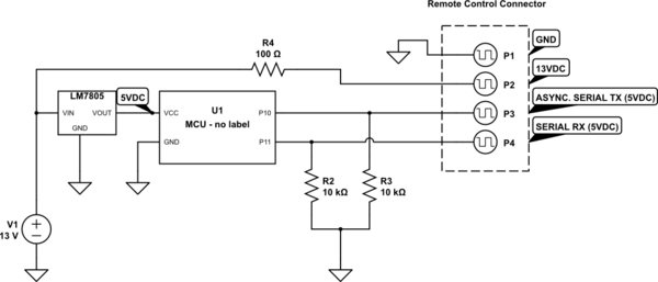 schematic
simulate this circuit – Schematic created using CircuitLab
The unit sends data in the following scenarios:
Temperature changed by turning control knob
Unit turned on/off by pressing control knob
Heater activated/deactivated (water flow start/stop)
My scope has built-in RS-232 decoding, and it does seem to decode some data
at 1200bps, but I am not sure I'm actually dealing with RS-232/UART data
here. My question to you is: what type of data does this look like to you?
Here is part of the output of an "ON" operation (i.e. press button to turn
heater On): WaveDromEditor
To me, this looks like too many high/low transitions for UART... I am
leaning toward a variable-width pulse to indicate 0/1. In the timing
diagram above, you see my interpretation of both RS-232 and "Other" which
indicates an unknown protocol, which would have a digital '0' as a 720uS
high pulse, and a digital '1' as a 24mS high pulse.
I would appreciate any insight into the protocol used here. If you need
clarifications I'll do my best.
RS-232/UART reference: https://electronics.stackexchange.com/a/227414/16378
Update: After recording and transcribing lots of waveforms from different
events, I have figured out part of the protocol.
There is a 'Start' command at the beginning of each sequence. It
consists of a logic Low for at least 4ms, then High for 7ms, then Low for
4ms.
After the 'Start' command, short pulses (720uS) represent logic Zero
and long pulses (2.4ms) represent logic One. The spaces between pulses are
all approx 840uS.
All sequences are 5 bytes long, and are transmitted 6 times.
The first 2 bytes are always the same: 00:FF:0F:F0
The third byte appears to be the command/event identifier:
Temperature setting change event (wheel turned): 00:70
ON command (button pressed): 00:00
OFF command (button pressed): 00:70 (same as temp. setting)
Flow start event: 02:70
Flow stop event: 00:70 (same as temp setting and Off command)
The fourth byte is the temperature in Fahrenheit, MSB to LSB (80 to
140)
The fifth byte is the temperature in Celsius, MSB to LSB (26 to 60)
So now I have to determine if I can send these same sequences into the RX
line to change temperatures and enable/disable the heater remotely. I
wonder if a different address is used
UPDATE #2: Success! It turns out, sending the same sequences to the RX pin
can be used to adjust the temperature and turn the unit on and off! It was
quite easy to bit-bang the protocol with an Arduino Uno, and the heater
responds to temperature settings by directly altering the output
temperature (no need to step upward/downward one degree at a time). I plan
to post the full interface guide along with source code for both input and
output when completed.
Thanks to everyone who offered suggestions!
UPDATE #3: Github repository created:
https://github.com/ryangriggs/EcoSmartLib
UPDATE #4: See Phil's github repo for further info:
https://github.com/PhilRW/ecosmart-remote
serialprotocolreverse-engineering
Share
Cite
Follow
edited Jun 9, 2018 at 2:24
asked May 10, 2016 at 15:16
Ryan Griggs's user avatar
Ryan Griggs
2,69622 gold badges3333 silver badges5555 bronze badges
Are you sure there are no labels on the MCU? The link you provided
features a picture of the control board, is that what you have? –
Dmitry Grigoryev
Commented May 10, 2016 at 15:41
@DmitryGrigoryev Yes that is the exact control board. However, the main
MCU has no etching at all. I have cleaned it, used a magnifier, etc, but
there is nothing printed on it. It is a 28-pin SOP28 package. –
Ryan Griggs
Commented May 10, 2016 at 15:50
It might be more recognizable if your timing waveform had a constant
time axis. As it is, its difficult to get a feel for the relative timing
just by looking at it. –
brhans
Commented May 10, 2016 at 17:58
Any idea what year is this device from? Maybe a date stamp on another
chip or the PCB? IF it's no longer manufactured and is old, that would
limit the available interfaces to check. – user68591
Commented May 10, 2016 at 18:39
@Wojciech I'm going to guess this device was manufactured around 2014,
and this model is still being actively manufactured/sold. Unfortunately
I've already put it back together and hate to disassemble everything to
check the date code. :) –
Ryan Griggs
Commented May 10, 2016 at 18:45
Show 5 more comments
1 Answer
Sorted by:
3
The Data Protocol that you showed in the linked document looks like the
modulation waveform common to some IR Remote Controls. It is possible that
the wired setup that you describe may be devised so that the remote
control link would also work if an IR receiver module were plugged into
the remote header. (Communications would be one way though).
Several common IR protocols are described in this document.
I would venture to guess that the two longer times (7msec/4msec) are the
start sync for the transmission. After the sync time the data looks to be
encoded in bit cells that are 1440 usec wide encoded as Manchester
modulation. One data level being 720usec high at the start of the cell and
720usec low in the second half of the cell. The opposite data level being
represented by the data line low for the 720usec at the start of the cell
and high in the second half of the bit cell.
This is definitely not an async format used by a typical UART protocol.
Share
Cite
Follow
answered May 10, 2016 at 15:36
Michael Karas's user avatar
Michael Karas
57.4k33 gold badges7171 silver badges138138 bronze badges
WOW that was a fast answer! Thanks Michael, I am researching the
Manchester modulation encoding now. I really appreciate your input! –
Ryan Griggs
Commented May 10, 2016 at 15:55
In Manchester encoding the longer sample should be twice as long as the
short one. Here I can see periods of 24mS, 7ms, 4ms and 720uS, none of
them satisfy that condition. Where have you seen 1440us? –
Dmitry Grigoryev
Commented May 10, 2016 at 15:59
two 720 us times showing near the front of the "data" waveform. –
Michael Karas
Commented May 10, 2016 at 22:58
that does look like an IR waveform, doesnt matter what protocol it lines up
with, you have at least a few controls and you have a scope or something
you have already captured this with. The long/sort up front looks like the
sync pattern, and after that consider the shorts, same size as the lows to
be zeros and the longer highs to be ones. –
old_timer
Commented May 11, 2016 at 0:41
ideally you want the properly matched led and carrier frequency, but you
can sacrifice distance and use 40K or 38K. What i would do first though is
while monitoring this interface, take any IR remote control you have and
aim it at the thing, if it generates waveforms on this interface, then
there you go, it is just dumb and passes them through, and "all you need
to do" is generate the right ir signal. –
old_timer
Commented May 11, 2016 at 0:43
schematic
simulate this circuit – Schematic created using CircuitLab
The unit sends data in the following scenarios:
Temperature changed by turning control knob
Unit turned on/off by pressing control knob
Heater activated/deactivated (water flow start/stop)
My scope has built-in RS-232 decoding, and it does seem to decode some data
at 1200bps, but I am not sure I'm actually dealing with RS-232/UART data
here. My question to you is: what type of data does this look like to you?
Here is part of the output of an "ON" operation (i.e. press button to turn
heater On): WaveDromEditor
To me, this looks like too many high/low transitions for UART... I am
leaning toward a variable-width pulse to indicate 0/1. In the timing
diagram above, you see my interpretation of both RS-232 and "Other" which
indicates an unknown protocol, which would have a digital '0' as a 720uS
high pulse, and a digital '1' as a 24mS high pulse.
I would appreciate any insight into the protocol used here. If you need
clarifications I'll do my best.
RS-232/UART reference: https://electronics.stackexchange.com/a/227414/16378
Update: After recording and transcribing lots of waveforms from different
events, I have figured out part of the protocol.
There is a 'Start' command at the beginning of each sequence. It
consists of a logic Low for at least 4ms, then High for 7ms, then Low for
4ms.
After the 'Start' command, short pulses (720uS) represent logic Zero
and long pulses (2.4ms) represent logic One. The spaces between pulses are
all approx 840uS.
All sequences are 5 bytes long, and are transmitted 6 times.
The first 2 bytes are always the same: 00:FF:0F:F0
The third byte appears to be the command/event identifier:
Temperature setting change event (wheel turned): 00:70
ON command (button pressed): 00:00
OFF command (button pressed): 00:70 (same as temp. setting)
Flow start event: 02:70
Flow stop event: 00:70 (same as temp setting and Off command)
The fourth byte is the temperature in Fahrenheit, MSB to LSB (80 to
140)
The fifth byte is the temperature in Celsius, MSB to LSB (26 to 60)
So now I have to determine if I can send these same sequences into the RX
line to change temperatures and enable/disable the heater remotely. I
wonder if a different address is used
UPDATE #2: Success! It turns out, sending the same sequences to the RX pin
can be used to adjust the temperature and turn the unit on and off! It was
quite easy to bit-bang the protocol with an Arduino Uno, and the heater
responds to temperature settings by directly altering the output
temperature (no need to step upward/downward one degree at a time). I plan
to post the full interface guide along with source code for both input and
output when completed.
Thanks to everyone who offered suggestions!
UPDATE #3: Github repository created:
https://github.com/ryangriggs/EcoSmartLib
UPDATE #4: See Phil's github repo for further info:
https://github.com/PhilRW/ecosmart-remote
serialprotocolreverse-engineering
Share
Cite
Follow
edited Jun 9, 2018 at 2:24
asked May 10, 2016 at 15:16
Ryan Griggs's user avatar
Ryan Griggs
2,69622 gold badges3333 silver badges5555 bronze badges
Are you sure there are no labels on the MCU? The link you provided
features a picture of the control board, is that what you have? –
Dmitry Grigoryev
Commented May 10, 2016 at 15:41
@DmitryGrigoryev Yes that is the exact control board. However, the main
MCU has no etching at all. I have cleaned it, used a magnifier, etc, but
there is nothing printed on it. It is a 28-pin SOP28 package. –
Ryan Griggs
Commented May 10, 2016 at 15:50
It might be more recognizable if your timing waveform had a constant
time axis. As it is, its difficult to get a feel for the relative timing
just by looking at it. –
brhans
Commented May 10, 2016 at 17:58
Any idea what year is this device from? Maybe a date stamp on another
chip or the PCB? IF it's no longer manufactured and is old, that would
limit the available interfaces to check. – user68591
Commented May 10, 2016 at 18:39
@Wojciech I'm going to guess this device was manufactured around 2014,
and this model is still being actively manufactured/sold. Unfortunately
I've already put it back together and hate to disassemble everything to
check the date code. :) –
Ryan Griggs
Commented May 10, 2016 at 18:45
Show 5 more comments
1 Answer
Sorted by:
3
The Data Protocol that you showed in the linked document looks like the
modulation waveform common to some IR Remote Controls. It is possible that
the wired setup that you describe may be devised so that the remote
control link would also work if an IR receiver module were plugged into
the remote header. (Communications would be one way though).
Several common IR protocols are described in this document.
I would venture to guess that the two longer times (7msec/4msec) are the
start sync for the transmission. After the sync time the data looks to be
encoded in bit cells that are 1440 usec wide encoded as Manchester
modulation. One data level being 720usec high at the start of the cell and
720usec low in the second half of the cell. The opposite data level being
represented by the data line low for the 720usec at the start of the cell
and high in the second half of the bit cell.
This is definitely not an async format used by a typical UART protocol.
Share
Cite
Follow
answered May 10, 2016 at 15:36
Michael Karas's user avatar
Michael Karas
57.4k33 gold badges7171 silver badges138138 bronze badges
WOW that was a fast answer! Thanks Michael, I am researching the
Manchester modulation encoding now. I really appreciate your input! –
Ryan Griggs
Commented May 10, 2016 at 15:55
In Manchester encoding the longer sample should be twice as long as the
short one. Here I can see periods of 24mS, 7ms, 4ms and 720uS, none of
them satisfy that condition. Where have you seen 1440us? –
Dmitry Grigoryev
Commented May 10, 2016 at 15:59
two 720 us times showing near the front of the "data" waveform. –
Michael Karas
Commented May 10, 2016 at 22:58
that does look like an IR waveform, doesnt matter what protocol it lines up
with, you have at least a few controls and you have a scope or something
you have already captured this with. The long/sort up front looks like the
sync pattern, and after that consider the shorts, same size as the lows to
be zeros and the longer highs to be ones. –
old_timer
Commented May 11, 2016 at 0:41
ideally you want the properly matched led and carrier frequency, but you
can sacrifice distance and use 40K or 38K. What i would do first though is
while monitoring this interface, take any IR remote control you have and
aim it at the thing, if it generates waveforms on this interface, then
there you go, it is just dumb and passes them through, and "all you need
to do" is generate the right ir signal. –
old_timer
Commented May 11, 2016 at 0:43