Nano Info


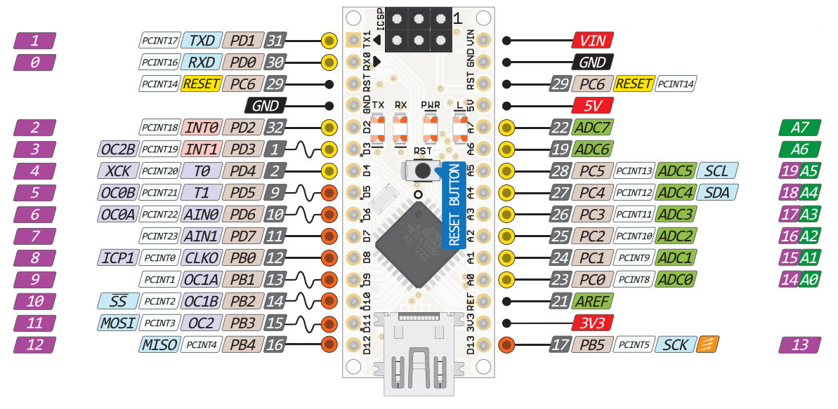
Note: the Nano's 3.3 volt output anly delivers 50Ma max!

CPU: ATmega328P Microcontroller is from 8-bit AVR family
Operating voltage 5V
Input voltage (Vin) 7V to 12V
Input/Output Pins 22
Analog I/O pins 6 from A0 to A5
Digital pins 14
Power consumption 19 mA
I/O pins DC Current 40 mA
Flash memory 32 KB
SRAM 2 KB
EEPROM 1 KB
CLK speed 16 MHz
Weight-7g
Size of printed circuit board 18 X 45mm
Supports three communications SPI, IIC, & USART
Power Pin Vin(30), 3.3V(17), 5V(27), GND(4, 29)
Vin board input voltage, external power source is used from 7V to 12V.
regulated power supply 5V nano board and it is used to give supply to board as well as components.
minimum voltage regulated from board voltage regulator 3.3V.
GND board ground pin
RST Pin( Reset): used to reset microcontroller
Analog Pins (A0-A7): are used to calculate analog voltage of board within range of 0V to 5V
I/O Pins (Digital Pins from D0 – D13): used as an i/p otherwise o/p pins. 0V & 5V
Serial Pins (Tx, Rx): used to transmit & receive TTL serial data.
External Interrupts (2, 3): used to activate an interrupt.
PWM (3, 5, 6, 9, 11): used to provide 8-bit of PWM output.
SPI (10, 11, 12, & 13): used for supporting SPI communication.
Inbuilt LED (13): This pin is used to activate LED.
IIC (A4, A5): used for supporting TWI communication.
AREF: used to give reference voltage to input voltage


Arduino Nano Name Type Function
1 D1/TX I/O Digital I/O Serial TX
2 D0/RX I/O Digital I/O Serial RX
3 RESET Input Reset (Active Low)
4 GND Power Supply Ground
5 D2 I/O Digital I/O
6 D3 I/O Digital I/O
7 D4 I/O Digital I/O
8 D5 I/O Digital I/O
9 D6 I/O Digital I/O
10 D7 I/O Digital I/O
11 D8 I/O Digital I/O
12 D9 I/O Digital I/O
13 D10 I/O Digital I/O SPI - SS
14 D11 I/O Digital I/O SPI - MOSI
15 D12 I/O Digital I/O SPI - MISO
16 D13 I/O Digital I/O SPI - SCK
17 3V3 Output +3.3V Output (from FTDI)
18 AREF Input ADC reference
19 A0 Input Analog Input Channel 0
20 A1 Input Analog Input Channel 1
21 A2 Input Analog Input Channel 2
22 A3 Input Analog Input Channel 3
23 A4 Input Analog Input Channel 4
24 A5 Input Analog Input Channel 5
25 A6 Input Analog Input Channel 6
26 A7 Input Analog Input Channel 7
27 +5V Output or Input +5V Output (From On-board Regulator) or +5V (Input from External Power Supply
28 RESET Input Reset ( Active Low)
29 GND Power Supply Ground
30 VIN Power Supply voltage

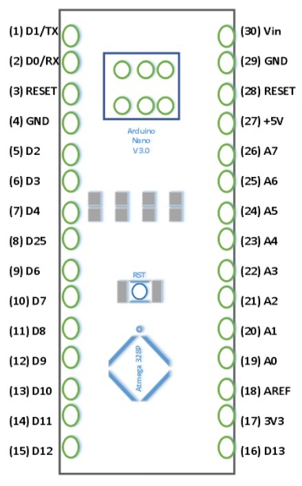
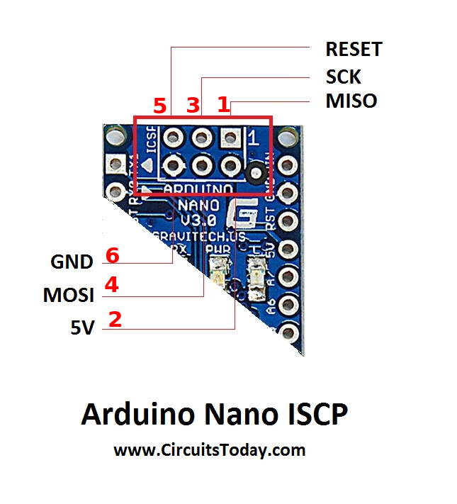
Nano ICSP PINS (13, 14,15,16)
ICSP Pin Name Type Function
1MISO Input or Output Master In Slave Out
2Vcc Output Supply Voltage
3SCKOutputClock from Master to Slave
4MOSI Output or Input Master Out Slave In
5RSTInputReset (Active Low)
6GND PowerSupply Ground


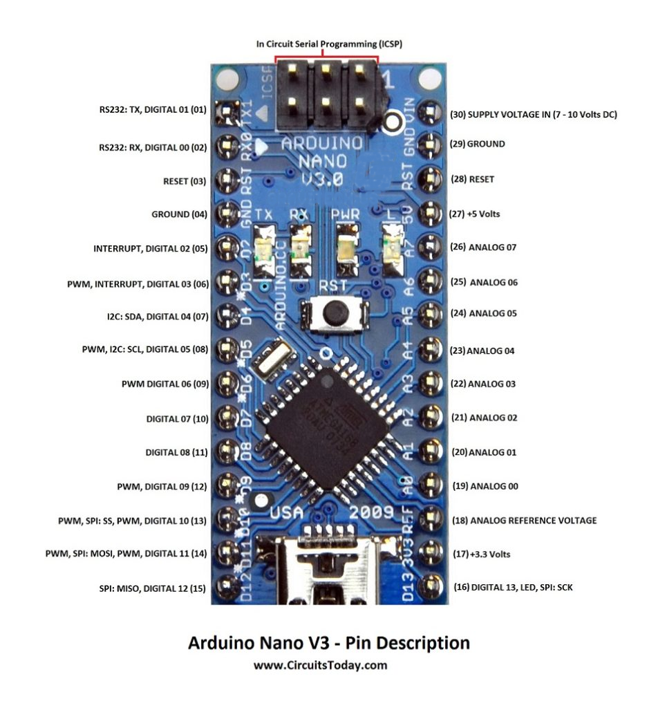
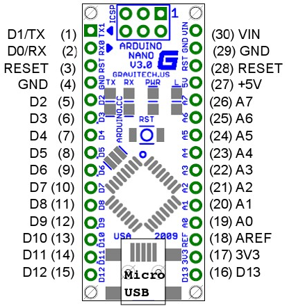
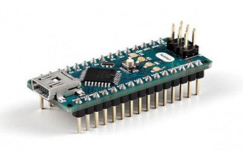
The Arduino Nano board is similar to an Arduino UNO board: same
 microcontroller:
Atmega328p.  Thus they can share a similar program.  The main difference 
between these two is size. Because Arduino Uno size is double to nano
 board. 
So Uno boards use more space on system. 
The programming of UNO can be done with a USB cable whereas Nano uses mini 
USB cable.  The main differences between these two are listed in following
 table.

Difference between Arduino UNO and Arduino Nano


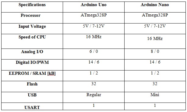
Arduino Nano Communication The communication of an Arduino Nano board can be done using different sources like using an additional Arduino board, a computer, otherwise using microcontrollers. The microcontroller using in Nano board (ATmega328) offers serial communication (UART TTL). This can be accessible at digital pins like TX, and RX. The Arduino software comprises of a serial monitor to allow easy textual information to transmit and receive from board. The TX & RX LEDs on Nano board will blink whenever information is being sent out through FTDI & USB link in direction of computer. The library-like SoftwareSerial allows serial communication on any of digital pins on board. The microcontroller also supports SPI & I2C (TWI) communication.


Programming The programming of an Arduino nano can be done using Arduino software. Click Tools option and select nano board. Microcontroller ATmega328 over Nano board comes with preprogrammed with a boot loader. This boot loader lets to upload new code without using an exterior hardware programmer. The communication of this can be done with STK500 protocol. Here boot loader can also be avoided & microcontroller program can be done using header of in-circuit serial programming or ICSP with an Arduino ISP.
Applications of Arduino Nano These boards are used to build Arduino Nano projects by reading inputs of a sensor, a button, or a finger and gives an output by turning motor or LED ON, or and some of applications are listed below.
Samples of electronic systems & products Automation
Several DIY projects
Control Systems
Embedded Systems Robotics
Instrumentation
Thus, this is all about an overview of Arduino nano datasheet. From above 
information finally, we can conclude that for beginners who are new to 
electronics, this Nano board is extremely suggested to go for this board
 due 
to its features like low cost and very simple to use in different
 applications.
This board can simply connect to any computer throughout its mini USB port.
 
Here is a question for you, what is an Arduino nano driver?

Interrupts
Please see the attachInterrupt reference page.
Board Digital Pins Usable For Interrupts
Uno, Nano, Mini, other 328-based 2, 3
Uno WiFi Rev.2, Nano Every all digital pins
Mega, Mega2560, MegaADK 2, 3, 18, 19, 20, 21 (pins 20 & 21 are not available to use for interrupts while they are used for I2C communication)
Micro, Leonardo, other 32u4-based 0, 1, 2, 3, 7
Zero all digital pins, except 4
MKR Family boards 0, 1, 4, 5, 6, 7, 8, 9, A1, A2
Nano 33 IoT 2, 3, 9, 10, 11, 13, A1, A5, A7
Nano 33 BLE, Nano 33 BLE Sense all pins
Due all digital pins
101 all digital pins (Only pins 2, 5, 7, 8, 10, 11, 12, 13 work with CHANGE)

From: https://docs.arduino.cc/learn/electronics/power-pins/ Power The Arduino Nano can be powered via the Mini-B USB connection, 6-20V unregulated external power supply (pin 30), or 5V regulated external power supply (pin 27). The power source is automatically selected to the highest voltage source. The Arduino Nano can accept a voltage between 7V and 12V through its VIN pin. So a 12V power supply would be within the allowable range. However, the current rating of the power supply (in this case 10A) is not as important as its voltage output. The amount of current drawn by the Arduino Nano will depend on the specific project and the components attached to it. Typically, the current draw is around 20-30mA when idle and up to a few hundred mA when actively performing tasks. As long as the power supply is able to provide enough current to meet the needs of the Arduino Nano and any other components connected to it, it should work fine. It's worth noting that it's generally recommended to use a regulated power supply with the Arduino Nano to ensure stable and reliable operation. If the power supply is unregulated, voltage fluctuations or spikes could potentially damage the board or attached components. Additionally, it's a good idea to check the polarity of the power supply to make sure that the positive terminal is connected to the VIN pin and the negative terminal is connected to ground, as reversing the polarity could also damage the board.
Powering Alternatives Arduino boards have five options in which they can be powered:
  1. Powering via USB connector
  2. Powering via the onboard barrel jack connector (if available on the board)
  3. Powering via the onboard battery connector (if available on the board)
  4. Powering via the VIN (Voltage In) pin
  5. Powering via the 3V3/5V pin*
*Powering your board via the 3V3/5V pins is not recommended, as it can damage your board's voltage regulator. Read more here. This article will examine these alternatives more in-depth.
USB Connector The most common and easiest way we can power an Arduino board is by using its onboard USB connector. The USB connector provides a regulated 5V line to power the board's electronics. However, 5V from the USB connector can also power external components through the 5V pin that can be found in Arduino boards. Micro USB connector of the Arduino Nano RP2040 board. Something important about the USB connection is the current rating of the USB host device. For example, a USB host device can be a computer; this means that the computer's USB port is the 5V power source of the Arduino board connected to it. Besides USB ports of computers, we can also use power banks, for example, as power sources for Arduino boards. Power banks usually have one or more USB outputs that provide regulated 5V lines at different current ratings. Arduino boards that run at 5V use the USB-regulated 5V line directly, boards that run at 3V3 regulate the 5V line from the USB connector to 3V3 using their onboard voltage regulator. Output current rating from the 5V pin will vary, depending on the 5V power source. Current from USB ports of computers is usually limited to 500mA.
Barrel Jack Some Arduino boards have an onboard barrel jack connector that is used to connect external power supplies. The Arduino boards with an onboard barrel jack connector are the following: Arduino boards with onboard barrel jacks are configured with positive polarity; this means a negative sleeve and a positive pin. Boards with an onboard barreljack use a negative 5.5mm sleeve and a 2.1mm positive pin The voltage line from the barrel jack connector is regulated in Arduino boards using their onboard voltage regulator; usually, it is first regulated to 5V and then regulated again to 3V3 in most Arduino boards. The recommended voltage and current ratings for external regulated DC power supplies connected to the barrel jack connector are summarized in the table below:
BoardExternal Power Supply Voltage (V)External Power Supply Current (A)
Arduino UNO Rev37-121
Arduino UNO WiFi Rev27-121.5
Arduino Leonardo7-121
Arduino Mega 2560 Rev37-121
Arduino Due7-121.5
Arduino Zero5-181

Battery The boards mentioned before have an onboard integrated battery charge management circuit. This circuit integrates the most common battery and power management functions, like a battery charger, a voltage regulator, and a load switch, all in one. Arduino boards with an onboard battery connector can work with single cell 3V7 Li-Ion and Li-polymer batteries
VIN The VIN pin in Arduino boards is a power pin with a dual function. This pin can work as a voltage input for regulated external power supplies that do not use a barrel jack connector. This pin can also work as a voltage output when an external power supply is connected to the barrel jack connector present in some Arduino boards. An important consideration is that the VIN pin is connected directly to the input pin of the onboard voltage regulator on Arduino boards. Since the VIN pin is directly connected to the voltage regulator, the VIN pin does not have reverse polarity protection. Use the VIN pin carefully to avoid damaging your Arduino board since it does not have reverse polarity protection. The minimum and maximum voltages that can be applied to the VIN pin are determined by the onboard voltage regulator on Arduino boards, varying from board to board. Those voltages are summarized in the table below:
BoardVIN Voltage (V)
UNO Mini5-18
UNO Rev37-12
UNO WiFi Rev27-12
UNO Rev3 SMD7-12
Leonardo7-12
Mega 2560 Rev37-12
Due7-12
Micro7-12
Zero5-18
Portenta H75
Nicla Sense ME5
Nano RP2040 Connect5-18
MKR NB 15005-7
MKR GSM 14005-7
MKR Vidor 40005-7
MKR WiFi 10105-7
MKR Zero5-5.5
MKR1000 WIFI5-5.5
MKR WAN 13005-5.5
MKR WAN 13105-7
Nano7-12
Nano Every7-18
Nano 33 IoT5-18
Nano 33 BLE5-18
Nano 33 BLE Sense5-18

3V3/5V Pin 3V3 and 5V pins are also power pins with a dual function. They can work as power outputs since these pins are directly connected to the onboard 3V3 and 5V voltage regulators outputs (depending on the board). Moreover, 3V3 and 5V pins can also be used as power inputs if no regulated power supply is connected through the other power inputs (USB port, barrel jack connector or VIN pin). Since 3V3 and 5V pins are directly connected to the onboard's 3V3 and 5V voltage regulators outputs, these pins have no reverse polarity protection. Use them carefully when working as power inputs to avoid damaging your board's voltage regulator. Although 3V3 and 5V pins can be used as power inputs, it is not recommended if no power supply is connected through the USB port, the barrel jack connector, or the VIN pin. 3V3 and 5V pins are connected directly to the onboard voltage regulator's output pin. Suppose the voltage in the voltage regulator output pin becomes higher than the input voltage of the voltage regulator. In that case, a large current may flow into the voltage regulator from its output pin to its input pin. That large current can permanently damage your board's voltage regulator. It is safe, but not recommended, to apply a voltage to the 3V3 or 5V pins that are not higher than the input voltage of the voltage regulators. The maximum current that can be drawn from the 3V3 and 5V pins when working as power outputs are summarized below. Notice that these currents can be provided by the 3V3 and 5V onboard voltage regulators, or from the power source connected to the board:
Board5V Pin Output Current (A)3V3 Pin Output Current (A)
UNO Mini10.5
UNO Rev310.15
UNO WiFi Rev210.5
UNO Rev3 SMD10.15
Leonardo10.15
Mega 2560 Rev30.80.05
Micro10.15
Zero10.5
Portenta H7-1
Nicla Sense ME*-0.5
Nano RP2040 Connect-1
MKR NB 1500-0.5
MKR Vidor 400010.3
MKR WiFi 101010.5
MKR Zero-0.5
MKR1000 WIFI-0.5
MKR WAN 1300-0.5
MKR WAN 1310-0.5
Nano0.80.15
Nano Every10.5
Nano 33 IoT10.5
Nano 33 BLE-1
Nano 33 BLE Sense-1

Choosing a Power Input Now that we know more about the powering alternatives of Arduino boards, we can answer that question we made at the beginning of this article about what power connector or pin we should use. When choosing a power connector or pin for a specific application or project, we should consider the available power source and the power budget of our application or project. A power budget analyzes how much power our application or project requires for its correct working. Let's talk about when it is recommended to use each of the options ways in which Arduino boards can be powered: USB Connector This option is often recommended when experimenting with small loads that require 5V; the current would be constrained by the USB host device where the board is connected.