Arduino Light Dimmers
From: https://forum.arduino.cc/t/solved-voltage-controlled-ac-dimmer/103051
2/18
Voltage controlled AC Dimmer
From: https://forum.arduino.cc/t/solved-voltage-controlled-ac-dimmer/103051/37
The problem with these tutorials (and all other examples, libraries and other
information I found online) is that it is controlled by phase cut percentage
and not by the actual voltage percentage. For example (assuming we have 220V
AC): 50% does not mean 110V. Instead, both in simulation (Proteus) and in a
real circuit I get 157V.
Here's the current code I'm using for testing purposes:
/*H*****************************************************
*
*******************************************************/
// =================== DEFINES =====================================
#define TRIAC 3
// =================== PROTOTYPES =====================================
void zero_crossing();
// =================== VARIABLES =====================================
/*F*****************************************************
*
*******************************************************/
void
setup()
{
pinMode( A0, INPUT );
pinMode( TRIAC, OUTPUT );
attachInterrupt( digitalPinToInterrupt( 2 ), zero_crossing, CHANGE);
}
/*F*****************************************************
*
*******************************************************/
void
loop()
{}
/*F*****************************************************
*
*******************************************************/
void
zero_crossing()
{
delayMicroseconds( map( analogRead( A0 ), 0, 1024, 0, 10000));
digitalWrite( TRIAC, HIGH );
delayMicroseconds( 10 );
digitalWrite( TRIAC, LOW);
}
And here's the circuit:
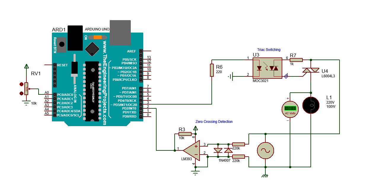 circuit
1268×662 19.6 KB
Yes, I know the code is not optimal and I should do as little as possible
in an interrupt routine, but this is just for testing purposes. I'll
replace the delay functions with actual timer interrupts in the future.
You might've noticed that I use a value of 1024 in the map function, and
that's because of the following article, but it should make much of a
difference:
https://create.arduino.cc/projecthub/dhorton668/a-better-mapping-with-map-dd
66f5?ref=partamp;ref_id=8233amp;offset=5 13
Another thing I want to mention is the attachInterrupt function. I use an
"on CHANGE" mode because I'm using LM393 for the zero crossing detection.
If I replace it with 4N25 (and of course, a bridge rectifier) I should use
a RISING mode pin interrupt. I've tried both LM393 and 4N25 zero crossing
detectore, but the results are the same.
Finally, I should also mention that when testing in real life, I use BT139
triac instead of the one shown on the image above.
So now, my question is:
Can I somehow calculate the amount of delay needed to achieve a given
voltage?
Here's an example, just to make things extra clear:
#define TRIAC 3
uint16_t triacDelay = 0;
/*F*****************************************************
* parameter voltage has a range of 0 to 220
*******************************************************/
uint16_t
get_delay_from_voltage( uint8_t voltage)
{
// Calculate delay according to given voltage
uint16_t delayAmount = 0;
// Perform the actual calculations here
// ...
// ...
// ...
return delayAmount;
}
/*F*****************************************************
*
*******************************************************/
void
zero_crossing()
{
delayMicroseconds( triacDelay );
digitalWrite( TRIAC, HIGH);
delayMicroseconds( 10 );
digitalWrite( TRIAC, LOW);
}
/*F*****************************************************
*
*******************************************************/
void
setup()
{
pinMode( TRIAC, OUTPUT);
attachInterrupt( digitalPinToInterrupt( 2 ), zero_crossing, CHANGE);
}
/*F*****************************************************
*
*******************************************************/
void
loop()
{
// code in loop function alternates between 100v and 200v each 5 seconds.
// that should have an output voltage of 100 volts
triacDelay = get_delay_from_voltage( 100 );
delay( 5000 );
// This means that we should have an output voltage of 200 volts
triacDelay = get_delay_from_voltage( 200 );
delay( 5000 );
}
Making a lookup table has crossed my mind, but I don't think it's the most
optimal solution, because of the need to test 220 values and create the
table according to the them.
I'd gladly provide any additional information needed and I'd greatly
appreciate any help.
Thanks in advance!
After much testing, here's what I ended up doing. Firstly, I used the
function that @anon90500195 suggested and programmed the MCU. uint16_t
get_delay_from_voltage(uint8_t voltage) { float stepValue = voltage /
220.0; return 10000 - round(asin(stepValue) / (PI / 2.0) * 10000); //
Amount of…
Popular Links
circuit
circuit1268×662 19.6 KB
Yes, I know the code is not optimal and I should do as little as possible
in an interrupt routine, but this is just for testing purposes. I'll
replace the delay functions with actual timer interrupts in the future.
You might've noticed that I use a value of 1024 in the map function, and
that's because of the following article, but it should make much of a
difference:
https://create.arduino.cc/projecthub/dhorton668/a-better-mapping-with-map-dd
66f5?ref=partamp;ref_id=8233amp;offset=5 13
Another thing I want to mention is the attachInterrupt function. I use an
"on CHANGE" mode because I'm using LM393 for the zero crossing detection.
If I replace it with 4N25 (and of course, a bridge rectifier) I should use
a RISING mode pin interrupt. I've tried both LM393 and 4N25 zero crossing
detectore, but the results are the same.
Finally, I should also mention that when testing in real life, I use BT139
triac instead of the one shown on the image above.
So now, my question is:
Can I somehow calculate the amount of delay needed to achieve a given
voltage?
Here's an example, just to make things extra clear:
#define TRIAC 3
uint16_t triacDelay = 0;
/*F*****************************************************
* parameter voltage has a range of 0 to 220
*******************************************************/
uint16_t
get_delay_from_voltage( uint8_t voltage)
{
// Calculate delay according to given voltage
uint16_t delayAmount = 0;
// Perform the actual calculations here
// ...
// ...
// ...
return delayAmount;
}
/*F*****************************************************
*
*******************************************************/
void
zero_crossing()
{
delayMicroseconds( triacDelay );
digitalWrite( TRIAC, HIGH);
delayMicroseconds( 10 );
digitalWrite( TRIAC, LOW);
}
/*F*****************************************************
*
*******************************************************/
void
setup()
{
pinMode( TRIAC, OUTPUT);
attachInterrupt( digitalPinToInterrupt( 2 ), zero_crossing, CHANGE);
}
/*F*****************************************************
*
*******************************************************/
void
loop()
{
// code in loop function alternates between 100v and 200v each 5 seconds.
// that should have an output voltage of 100 volts
triacDelay = get_delay_from_voltage( 100 );
delay( 5000 );
// This means that we should have an output voltage of 200 volts
triacDelay = get_delay_from_voltage( 200 );
delay( 5000 );
}
Making a lookup table has crossed my mind, but I don't think it's the most
optimal solution, because of the need to test 220 values and create the
table according to the them.
I'd gladly provide any additional information needed and I'd greatly
appreciate any help.
Thanks in advance!
After much testing, here's what I ended up doing. Firstly, I used the
function that @anon90500195 suggested and programmed the MCU. uint16_t
get_delay_from_voltage(uint8_t voltage) { float stepValue = voltage /
220.0; return 10000 - round(asin(stepValue) / (PI / 2.0) * 10000); //
Amount of…
Popular Links
There are 49 replies with an estimated read time of 6 minutes.
Sep 2022post #2
Put on your thinking (math) hat. The phase is the phase of a sine wave.
It's a mathematical function. Every trigonometric function has an inverse.
That's all I will say.
Edit - except, how did you come up with the value 220 for the number of
table entries in the lookup table? I do hope it has nothing to do with the
voltage...
Not sure what you mean, "optimal". Or "test 220 values". If you have to
make a lookup table, it's done only once at boot time. There is no
testing, it's all calculated.
Also if you seek perceptual brightness changes, you have to factor gamma
into the luminance function.
LanternMG
Here's what I've been trying:
/*H*****************************************************
* Zero crossing detection
*******************************************************/
// =================== DEFINES =====================================
#define TRIAC 3
// =================== VARIABLES =====================================
uint16_t triacDelay = 0;
// =================== PROTOTYPES =====================================
uint16_t get_delay_from_voltage(uint8_t voltage);
void zero_crossing();
/*F*****************************************************
*
*******************************************************/
void
setup()
{
Serial.begin( 9600 );
pinMode( TRIAC, OUTPUT);
attachInterrupt( digitalPinToInterrupt( 2 ), zero_crossing, CHANGE);
}
/*F*****************************************************
*
*******************************************************/
void
loop()
{
triacDelay = get_delay_from_voltage( 110 ); // Instead of 110v, I get 158v
Serial.println( triacDelay );
delay( 5000 );
triacDelay = get_delay_from_voltage( 55 ); // Instead of 55v, I get 100v
Serial.println( triacDelay );
delay( 5000 );
}
/*F*****************************************************
*
*******************************************************/
uint16_t
get_delay_from_voltage(uint8_t voltage)
{
double stepValue = (voltage * (2.0 / 220)) - 1.0;
return round((acos(stepValue) / M_PI) * 10000); // Amount of
microseconds
}
/*F*****************************************************
*
*******************************************************/
void
zero_crossing()
{
delayMicroseconds( triacDelay);
digitalWrite( TRIAC, HIGH);
delayMicroseconds( 10 );
digitalWrite( TRIAC, LOW);
}
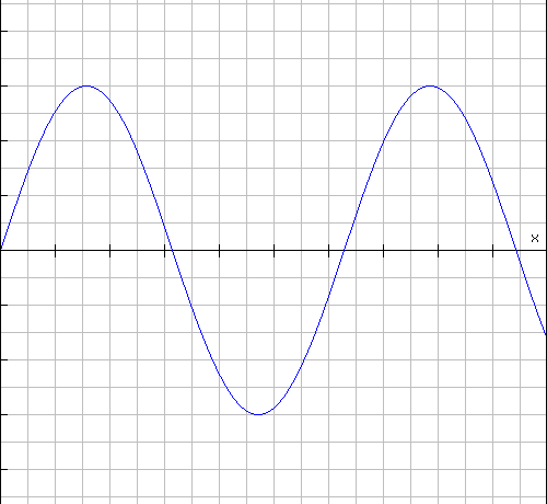
Here's the AC signal when I call get_delay_from_voltage(110);
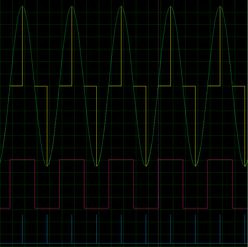 osc1
osc1803×801 4.74 KB
osc1
osc1803×801 4.74 KB
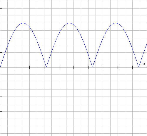
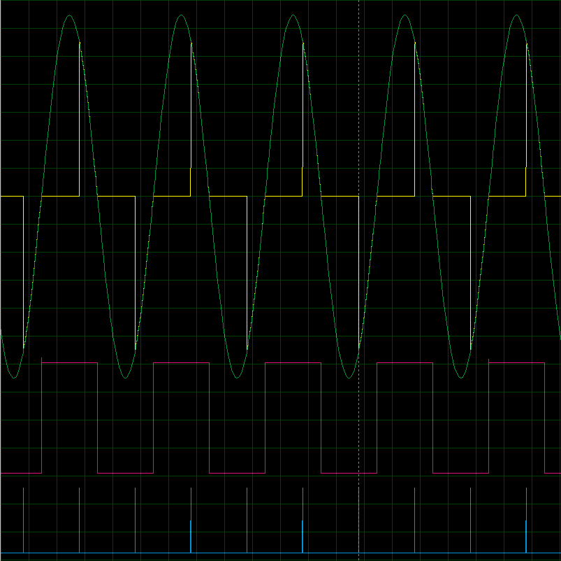 And here's the AC signal when I call get_delay_from_voltage(55);
osc2
osc2803×802 4.42 KB
And here's the AC signal when I call get_delay_from_voltage(55);
osc2
osc2803×802 4.42 KB
Dimmer-2
From: https://www.instructables.com/Arduino-controlled-light-dimmer-The-circuit
Arduino Controlled Light Dimmer
By diy_bloke in CircuitsMicrocontrollers
 Introduction: Arduino Controlled Light Dimmer
WAIT!!
before you decide to build this, it is good to know that a similar dimmer
is available at Aliexpress at cost that is hard to beat (currently 2.70
euro)
WARNING:
Some people try to build this with an optocoupler with zerocrossing coz
'that is better' right? Some are even told in electronics shops it is
better to use such an optocoupler. WRONG. This will only work with a
random fire optocoupler: NOT igniting at zerocrossing is the principle of
this dimmer.
Switching an AC load with an Arduino is rather simpel: either a mechanical
relay or a solid state relay with an optically isolated Triac. (I say
Arduino, but if you use an 8051 or PIC16F877A microcontroller, there is
stuff for you too here.)
It becomes a bit more tricky if one wants to dim a mains AC lamp with an
arduino: just limiting the current through e.g. a transistor is not really
possible due to the large power the transistor then will need to
dissipate, resulting in much heat and it is also not efficient from an
energy use point of view.
Introduction: Arduino Controlled Light Dimmer
WAIT!!
before you decide to build this, it is good to know that a similar dimmer
is available at Aliexpress at cost that is hard to beat (currently 2.70
euro)
WARNING:
Some people try to build this with an optocoupler with zerocrossing coz
'that is better' right? Some are even told in electronics shops it is
better to use such an optocoupler. WRONG. This will only work with a
random fire optocoupler: NOT igniting at zerocrossing is the principle of
this dimmer.
Switching an AC load with an Arduino is rather simpel: either a mechanical
relay or a solid state relay with an optically isolated Triac. (I say
Arduino, but if you use an 8051 or PIC16F877A microcontroller, there is
stuff for you too here.)
It becomes a bit more tricky if one wants to dim a mains AC lamp with an
arduino: just limiting the current through e.g. a transistor is not really
possible due to the large power the transistor then will need to
dissipate, resulting in much heat and it is also not efficient from an
energy use point of view.
Phase cutting
One way of doing it is through phase control with a Triac: the Triac then
is fully opened, but only during a part of the sinus AC wave. This is
called leading edge cutting.
One could let an Arduino just open the Triac for a number of microseconds,
but that has the problem that it is unpredictable during what part of the
sinus wave the triac opens and therefore the dimming level is
unpredictable. One needs a reference point in the sinus wave.
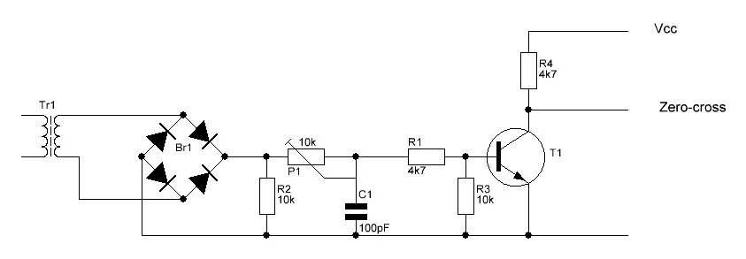
For that a zero crossing detector is necessary. This is a circuit that
tells the Arduino (or another micro controller) when the sinus-wave goes
through zero and therefore gives a defined point on that sinus wave.
Opening the Triac after a number of microseconds delay starting from the
zero crossing therefore gives a predictable level of dimming.
Pulse Skip Modulation
Another way of doing this is by Pulse Skip Modulation. With PSM, one or
more full cycles (sinewaves) are transferred to the load and then one or
more cycles are not. Though effective, it is not a good way to dim lights
as there is a chance for flickering. Though it might be tempting, in PSM
one should always allow a full sinewave to be passed to the load, not a
half sinus as in that case the load will be fed factually from DC which is
not a good thing for most AC loads. The difference between leading edge
cutting and PSM is mainly in the software: in both cases one will need a
circuit that detects the zero crossing and that can control a triac.
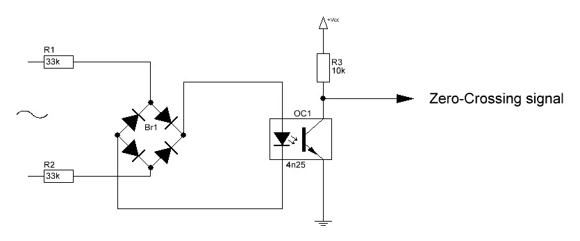
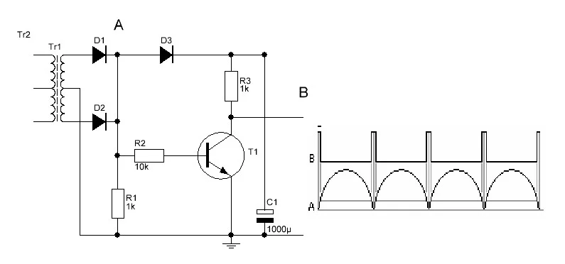
A circuit that can do this is easy to build: The zero crossing is directly
derived from the rectified mains AC lines – via an optocoupler of
course- and gives a signal every time the wave goes through zero. Because
the sine wave first goes through double phased rectification, the
zero-crossing signal is given regardless whether the sinus wave goes up
through zero or down through zero. This signal then can be used to trigger
an interrupt in the Arduino.
PWM dimming
PWM dimming, as in LEDs is not done frequently with AC loads for a number
of reasons. It is possible though. Check this instructable to see how.
It goes without saying that there needs to be a galvanic separation between
the Arduino side of things and anything connected to the mains. For those
who do not understand 'galvanic separation' it means 'no metal
connections' thus ---> opto-couplers. BUT, if you do not understand
'galvanic separation', maybe you should not build this.
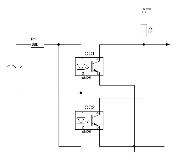
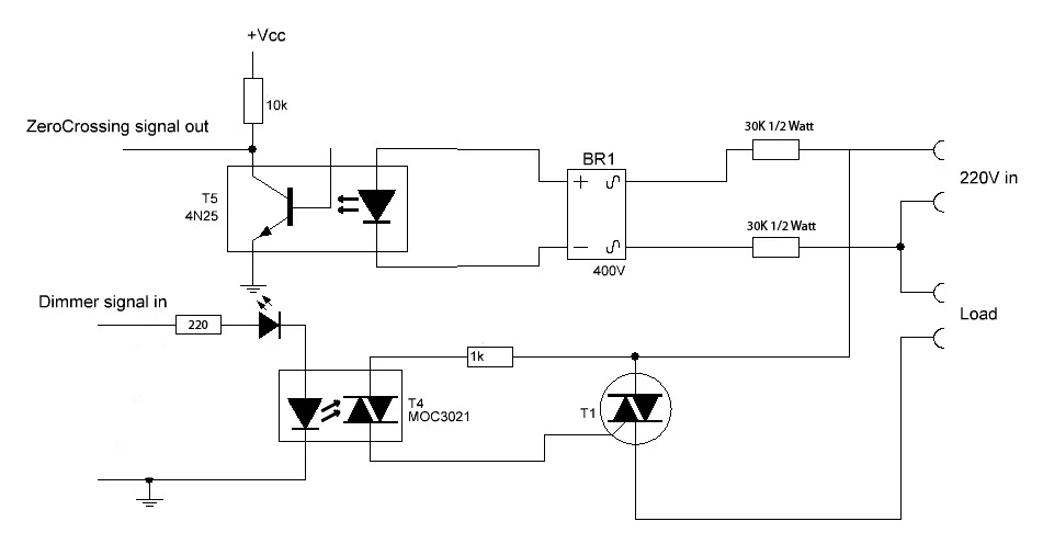
The circuit pictured here does just that. The mains 220Volt voltage is led
through two 30k resistors to a bridge rectifier that gives a double phased
rectified signal to a 4N25 opto-coupler. The LED in this opto-coupler thus
goes low with a frequency of 100Hz and the signal on the collector is
going high with a frequency of 100Hz, in line with the sinusoid wave on
the mains net. The signal of the 4N25 is fed to an interrupt pin in the
Arduino (or other microprocessor). The interrupt routine feeds a signal of
a specific length to one of the I/O pins. The I/O pin signal goes back to
our circuit and opens the LED and a MOC3021, that triggers the
Opto-Thyristor briefly. The LED in series with the MOC3021 indicates if
there is any current going through the MOC3021. Mind you though that in
dimming operation that light will not be very visible because it is very
short lasting. Should you chose to use the triac switch for continuous
use, the LED will light up clearly.
Mind you that only regular incandescent lamps are truly suitable for
dimming. It will work with a halogen lamp as well, but it will shorten the
life span of the halogen lamp. It will not work with any cfl lamps, unless
they are specifically stated to be suited for a dimmer. The same goes for
LED lamps
NOTE!
It is possible that depending on the LED that is used, the steering signal
just does not cut it and you may end up with a lamp that just flickers
rather than being smoothly regulated. Replacing the LED with a wire bridge
will cure that. The LED is not really necessary. increase the 220 ohm
resistor to 470 then
STOP:
This circuit is attached to a 110-220 Voltage. Do not build this if you are
not confident about what you are doing. Unplug it before coming even close
to the PCB. The cooling plate of the Triac is attached to the mains. Do
not touch it while in operation. Put it in a proper enclosure/container.
WAIT:
Let me just add a stronger warning here: This circuit is safe if it is
built and implemented only by people who know what they are doing. If you
have no clue or if you are doubting about what you do, chances are you are
going to be DEAD!DO NOT TOUCH WHEN IT IS CONNECTED TO THE GRID
Materials
Zerocrossing
- 4N25 €0.25 or H11AA1 or IL250, IL251, IL252, LTV814 (see text in the next
step)
- Resistor 10k €0.10
- bridge rectifier 400 Volt €0.30
- 2x 30 k resistor 1/2 Watt (resistors will probably dissipate 400mW max each
- €0.30
- 1 connector €0.20
- 5.1 Volt zenerdiode (optional)
Lamp driver
- LED (Note: you can replace the LED with a wire bridge as the LED may
sometimes cause the lamp to flicker rather than to regulate smoothly)
- MOC3021 If you chose another type, make sure it has NO zero-crossing
detection, I can't stress this enough DO NOT use e.g. a MOC3042
- Resistor 220 Ohm €0.10 (I actually used a 330 Ohm and that worked fine)
- Resistor 470 Ohm-1k (I ended up using a 560 Ohm and that worked well)
- TRIAC TIC206 €1.20 or BR136 €0.50
- 1 connector €0.20
Other
- Piece of PCB 6x3cm
- electric wiring
That is about €3 ($3.22 USD) in parts
Step 1: Arduino Controlled Light Dimmer: the PCB
 Arduino Controlled Light Dimmer: the PCB
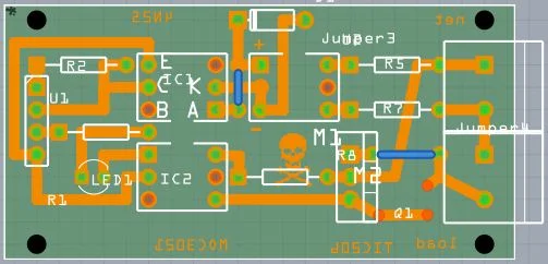
You will find two pictures for the PCB: my first one, that I leave here for
documentation purposes and a slightly altered new one. The difference is that
I left out the zenerdiode as it is not really necessary and I gave the LED
itś own (1k) resistor: it is no longer in series with the Optocoupler, that
now has a 470 Ohm resistor. I made the PCB via direct toner transfer and
then etched it in a hydrochloric acid/Hydrogenperoxide bath. There are plenty
of instructables telling how to do that. You can use the attached print
design to do the same. Populating the print is quite straightforward. I
used IC feet for the opto-couplers and the bridge rectifier.
Download the print here.
Note:
You need Fritzing for this. For the direct toner transfer, the
printed side of the printed pdf file, goes directly against the copper
layer for transfer. Once it is transferred, you will be looking at the ink
from the other side and thus see the text normal again. I made slight
alterations in thePCB: I removed the zenerdiode and the LED is no longer
in series with the optocoupler.
I used a TIC206. That can deliver 4 amperes. Keep in mind though that the
copper tracks of the PCB will not be able to withstand 4 Amperes. For any
serious load, solder a piece of copper installation wire on the tracks
leading from the TRIAC to the connectors and on the track between the two
connectors.
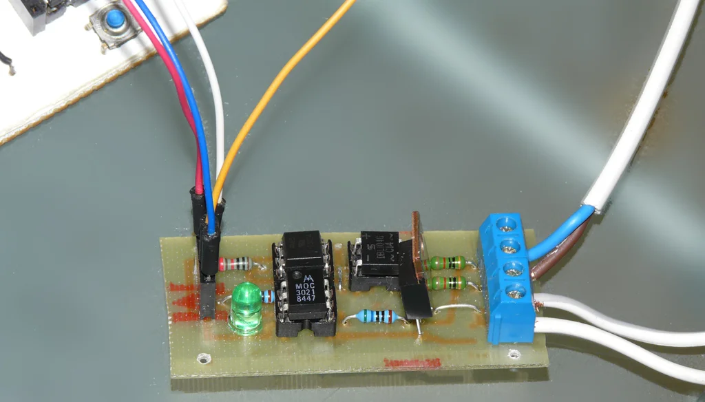
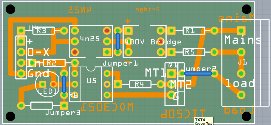
In case it is not clear what the inputs are: from top to bottom on the 2nd picture:
Arduino Controlled Light Dimmer: the PCB
You will find two pictures for the PCB: my first one, that I leave here for
documentation purposes and a slightly altered new one. The difference is that
I left out the zenerdiode as it is not really necessary and I gave the LED
itś own (1k) resistor: it is no longer in series with the Optocoupler, that
now has a 470 Ohm resistor. I made the PCB via direct toner transfer and
then etched it in a hydrochloric acid/Hydrogenperoxide bath. There are plenty
of instructables telling how to do that. You can use the attached print
design to do the same. Populating the print is quite straightforward. I
used IC feet for the opto-couplers and the bridge rectifier.
Download the print here.
Note:
You need Fritzing for this. For the direct toner transfer, the
printed side of the printed pdf file, goes directly against the copper
layer for transfer. Once it is transferred, you will be looking at the ink
from the other side and thus see the text normal again. I made slight
alterations in thePCB: I removed the zenerdiode and the LED is no longer
in series with the optocoupler.
I used a TIC206. That can deliver 4 amperes. Keep in mind though that the
copper tracks of the PCB will not be able to withstand 4 Amperes. For any
serious load, solder a piece of copper installation wire on the tracks
leading from the TRIAC to the connectors and on the track between the two
connectors.
In case it is not clear what the inputs are: from top to bottom on the 2nd picture:
- +5Volts
- Interrupt signal (going to D2 on arduino)
- Triac signal (coming from D3 on Arduino)
- Ground
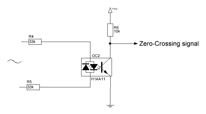
NOTE:
If you have an H11AA1or IL 250, 251 or 252 opto-coupler then you do not
need the bridge rectifier. These have two anti-parellel diodes and thus
can handle AC. It is pin compatible with the 4N25, just pop it in and
solder 2 wire-bridges between R5 and + and R7 and -. The LTV814 is not
pincompatible
Step 2: A Word on Inductive Loads:
A Word on Inductive Loads: Theory
 The presented circuit is suited for pure resistive loads such as incandescent
lamps.
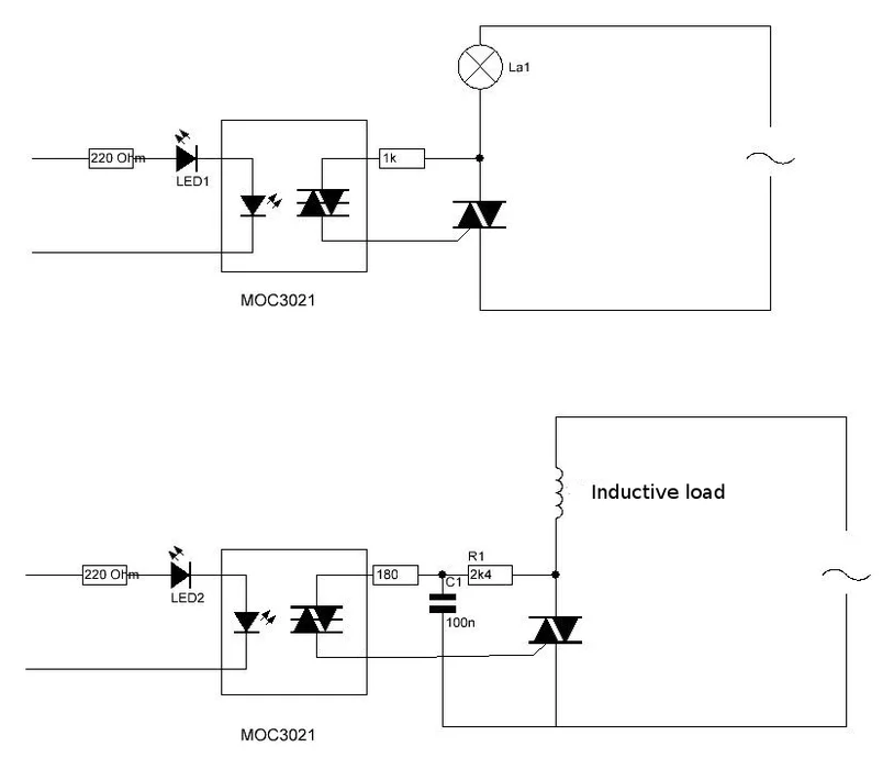
Should you want to use it for inductive loads, then a snubber circuit is
necessary. The figure shows the modifications for use with Inductive
loads. Mind you, this is not something I tried as I just wanted to dim
lamps, but it is based on examples and theory available on the internet.
You would have to adapt the provided PCB
The top figure shows the circuit as is, for dimming a lamp. It is in all
its simplicity just a resistor to trigger the gate via the diac in the
optocoupler. The value of 1k may be changed as discussed in the text
before.
The bottom figure gives an omnipresent circuit for use in inductive loads.
It consists of an additional resistor and capacitor. The gate current is
below 15mA. If you are using a less sensitive triac to control the
inductive load, reduce the resistor from 2.4kΩ to 1.2kΩ, providing more
current to drive the triac and increase the capacitor to 200nF. This
snubber circuit is there to protect the triac from the high voltage
generated from an inductive load. The feedback may cause some problem for
non-inductive load. The small leakage can be significant enough to turn on
small load (for example a lamp).
There are other snubber circuits, e.g. a resistor and capacitor in series
directly over the load
The presented circuit is suited for pure resistive loads such as incandescent
lamps.
Should you want to use it for inductive loads, then a snubber circuit is
necessary. The figure shows the modifications for use with Inductive
loads. Mind you, this is not something I tried as I just wanted to dim
lamps, but it is based on examples and theory available on the internet.
You would have to adapt the provided PCB
The top figure shows the circuit as is, for dimming a lamp. It is in all
its simplicity just a resistor to trigger the gate via the diac in the
optocoupler. The value of 1k may be changed as discussed in the text
before.
The bottom figure gives an omnipresent circuit for use in inductive loads.
It consists of an additional resistor and capacitor. The gate current is
below 15mA. If you are using a less sensitive triac to control the
inductive load, reduce the resistor from 2.4kΩ to 1.2kΩ, providing more
current to drive the triac and increase the capacitor to 200nF. This
snubber circuit is there to protect the triac from the high voltage
generated from an inductive load. The feedback may cause some problem for
non-inductive load. The small leakage can be significant enough to turn on
small load (for example a lamp).
There are other snubber circuits, e.g. a resistor and capacitor in series
directly over the load
Step 3: The Software, a Bit of Theory
The Software, a Bit of Theory
 If you could care less about theory, but just want software, go to next step
The way to use an AC dimmer/fader is quite simple once you understand the basics:
In AC the power fed to lamp is directly related to total surface of sinewave,
lamp can be regulated by only allowing a predictable part of that sinewave
to flow through lamp.
As such we need a reference point on that sinus from where we calculate when
the lamp has to be switched on.
The easiest reference point to use is the so called 'zero crossing': the moment
that the light goes through zero.
After each zero crossing there is one full half of the sinewave available
to send through the lamp.
So what the software needs to do is to detect the zerocrossing, and then
wait for a set amount of time on that sinewave to switch on the TRIAC.
There are 2 major grid frequencies in the world:
50Hz in Europe and most of Asia and Africa and 60 Hz in the America's (and
parts of the Caribean). There are 2 major voltages in the world: 110-120V
and 220-240V but they are not important for the mathematics here
For ease of use I will take the 50Hz frequency as an example:
50Hz is 50 waves per second.
Each sinewave thus takes 1000ms/50=20ms (miliseconds)
As there are 2 sinuspeaks in a wave that means that after every zero
detection there is a 10ms period that we can regulate.
Should we ignite the lamp directly at the beginning of that period, the
lamp will receive full power, should we do it at the end of that 10ms
period the lamp will receive no ower and should we do it halfway, the lamp
will receive half power.
As we are using TRIACs, what the software needs to do is to wait for the
zero point at the sinuscurve, take note of that and then wait a specified
amount of time within that 10ms period to send a pulse to the TRIAC.
If it sends that pulse at 5ms, the lamp will only burn at half power.
In the Circuit, the zero detection is done by the biphase optocoupler and
is available as the X-signal on the board.
There are basically 2 ways for a microcontroller to detect that signal:
1-a continuous 'polling' of the Zero Crossing pin
2-using an interrupt to tell the program that there was a zero crossing
The main difference between the two is that in 'polling' everytime the
computer goes through it's main loop it needs to check the pin. If your
program is busy doing a lot of other things, it might be too late in
checking the zero crossing pin, while when using an interrupt, it does not
matter what the program is busy with. The interrupt is sort of 'tapping it
on the shoulder' saying "Hey look, something came up that you need to
attend to NOW".
After the zero crossing is detected the program needs to wait for a
specified amount of time and then switch on the TRIAC.
Also here, that waiting can be done in two different ways
1- by issuing a 'wait' command
2-by using a timer interrupt
Again, both these methods have their pro's and con's. The 'wait' command
('delay' in Arduino language) literally let's the computer wait for the
required time and it cant do anything else in the mean time. if the lamp
is burning at low power by letting the computer wait say 9ms, that means
that every 10ms the computer is told to wait 9ms: ergo it will be idle 90%
of the time. That is fine if your controller is only used to control the
lamp, but if it needs to do other stuff then little time is left.
Using a timer interrupt solves that. Basically what that does is that the
program tells the timer: ¨Hey, I just heard we have a zero crossing, I
got to do something else, but you just wait 4.5ms and then switch on the
Triac" So the program goes on it's merry way and 4.5ms (as an example)
after it was given notice there was a 0-crossing, the timer switches on
the TRIAC.
Polling:
(note this is a rough example for illustration of polling, obviously it needs
some enhancement)
/*H*****************************************************
*
*******************************************************/
// ==================== DEFINES ==================================
// ==================== PROTOTYPES ==================================
// ==================== VARIABLES ==================================
int AC_LOAD =3; // WE USE PIN 3 TO IGNITE TRIAC
int state; // INTEGER TO STORE STATUS OF ZERO CROSSING
/*F*****************************************************
*
*******************************************************/
void
setup()
{
pinMode( AC_LOAD, OUTPUT ); // SET AC lOAD PIN AS OUTPUT
}
/*F*****************************************************
*
*******************************************************/
void
loop()
{
state = digitalRead( AC_LOAD);
if( state =1 )
{
delayMicroseconds( 5000 ); // =5 ms=half power
digitalWrite( AC_LOAD, HIGH); // triac firing
}
}
If you could care less about theory, but just want software, go to next step
The way to use an AC dimmer/fader is quite simple once you understand the basics:
In AC the power fed to lamp is directly related to total surface of sinewave,
lamp can be regulated by only allowing a predictable part of that sinewave
to flow through lamp.
As such we need a reference point on that sinus from where we calculate when
the lamp has to be switched on.
The easiest reference point to use is the so called 'zero crossing': the moment
that the light goes through zero.
After each zero crossing there is one full half of the sinewave available
to send through the lamp.
So what the software needs to do is to detect the zerocrossing, and then
wait for a set amount of time on that sinewave to switch on the TRIAC.
There are 2 major grid frequencies in the world:
50Hz in Europe and most of Asia and Africa and 60 Hz in the America's (and
parts of the Caribean). There are 2 major voltages in the world: 110-120V
and 220-240V but they are not important for the mathematics here
For ease of use I will take the 50Hz frequency as an example:
50Hz is 50 waves per second.
Each sinewave thus takes 1000ms/50=20ms (miliseconds)
As there are 2 sinuspeaks in a wave that means that after every zero
detection there is a 10ms period that we can regulate.
Should we ignite the lamp directly at the beginning of that period, the
lamp will receive full power, should we do it at the end of that 10ms
period the lamp will receive no ower and should we do it halfway, the lamp
will receive half power.
As we are using TRIACs, what the software needs to do is to wait for the
zero point at the sinuscurve, take note of that and then wait a specified
amount of time within that 10ms period to send a pulse to the TRIAC.
If it sends that pulse at 5ms, the lamp will only burn at half power.
In the Circuit, the zero detection is done by the biphase optocoupler and
is available as the X-signal on the board.
There are basically 2 ways for a microcontroller to detect that signal:
1-a continuous 'polling' of the Zero Crossing pin
2-using an interrupt to tell the program that there was a zero crossing
The main difference between the two is that in 'polling' everytime the
computer goes through it's main loop it needs to check the pin. If your
program is busy doing a lot of other things, it might be too late in
checking the zero crossing pin, while when using an interrupt, it does not
matter what the program is busy with. The interrupt is sort of 'tapping it
on the shoulder' saying "Hey look, something came up that you need to
attend to NOW".
After the zero crossing is detected the program needs to wait for a
specified amount of time and then switch on the TRIAC.
Also here, that waiting can be done in two different ways
1- by issuing a 'wait' command
2-by using a timer interrupt
Again, both these methods have their pro's and con's. The 'wait' command
('delay' in Arduino language) literally let's the computer wait for the
required time and it cant do anything else in the mean time. if the lamp
is burning at low power by letting the computer wait say 9ms, that means
that every 10ms the computer is told to wait 9ms: ergo it will be idle 90%
of the time. That is fine if your controller is only used to control the
lamp, but if it needs to do other stuff then little time is left.
Using a timer interrupt solves that. Basically what that does is that the
program tells the timer: ¨Hey, I just heard we have a zero crossing, I
got to do something else, but you just wait 4.5ms and then switch on the
Triac" So the program goes on it's merry way and 4.5ms (as an example)
after it was given notice there was a 0-crossing, the timer switches on
the TRIAC.
Polling:
(note this is a rough example for illustration of polling, obviously it needs
some enhancement)
/*H*****************************************************
*
*******************************************************/
// ==================== DEFINES ==================================
// ==================== PROTOTYPES ==================================
// ==================== VARIABLES ==================================
int AC_LOAD =3; // WE USE PIN 3 TO IGNITE TRIAC
int state; // INTEGER TO STORE STATUS OF ZERO CROSSING
/*F*****************************************************
*
*******************************************************/
void
setup()
{
pinMode( AC_LOAD, OUTPUT ); // SET AC lOAD PIN AS OUTPUT
}
/*F*****************************************************
*
*******************************************************/
void
loop()
{
state = digitalRead( AC_LOAD);
if( state =1 )
{
delayMicroseconds( 5000 ); // =5 ms=half power
digitalWrite( AC_LOAD, HIGH); // triac firing
}
}
Interrupt driven:
To use an interrupt, first we need to set that up. On the Arduino that is as follows:
/*F*****************************************************
*
*******************************************************/
void
setup()
{
pinMode( AC_LOAD, OUTPUT ); // Set AC Load pin as output
attachInterrupt( 0, zero_crosss_int, RISING); // zero cross IRQ # from table
}
What this says is that the interrupt is attached to interrupt 0, it goes to
a function called "zero_crosss_int" and it reacts to a rising flank on the
pin.
In the Zero_cross_int function that the program jumps to after the
interrupt we determine the time we need to wait before firing the TRIAC.
We will also add a bit of functionality. We don't just want one level set
that the lamp burns on, we are going to add some functionality to regulate
the light level in steps.
For that I have chosen the fully arbitrary amount of 128 steps. That means
that every step is 10ms/128 = 10000us/128=75us (in fact it is 78, but I
get to that later). The total dimtime then is calculated from 75x(1 to
128). The number between 1-128, which determines our level of dimming, we
assign to the variable integer 'dimming'
/*F*****************************************************
* func fired at zero crossing to dim light
*******************************************************/
void
zero_crosss_int()
{
int dimtime = (75 * dimming); // For 60Hz =>65
delayMicroseconds( dimtime ); // Off cycle
digitalWrite( AC_LOAD, HIGH ); // triac firing
delayMicroseconds( 10 ); // triac On propagation delay (for 60Hz use 8.33 )
digitalWrite( AC_LOAD, LOW ); // triac Off
}
What happens here is that the program first calculates the dimtime (=time
to wait before the triac is fired)
It then waits that amount of time, subsequently waits that amount of time
and fires the Triac. The Triac will switch off again at the following zero
crossing, but we are going to already write a low on the TRIAC pin to
avoid accidental ignition in the next cycle. We need to wait a bit however
to know for sure the TRIAC is on, so we wait 10us. Now (10000-10)/128 is
still 78 but i found 75 to work well. Feel free to use 78 though.
The only thing then left to do in the main program is to set the level at
which we want the lamp to burn:
/*F*****************************************************
*
*******************************************************/
void
loop()
{
int ndx;
for (ndx =5; ndx < 128; ndx++)
{
dimming =ndx;
delay( 10 );
}
...
}
What happens here is a simple loop that regulates the lamp up in a 128
steps. I have chosen not to start at 1 but at 5 because at that level
there could be some timing issues that could cause the lamp to flicker.
The above program is only an example of how to control the lamp, obviously
you want to add some other functionality rather than just have a lamp go
up and down in brightness.
Using a timer:
If you want your program to be time efficient you will need to use an
interrupt for the zero-crossing detection and a timer to determine the
amount of time to wait.
Roughly a program would look as follows:
Initialize
Set up the various constants and variables you need and include the
libraries used (such as the TimerOne Library)
Setup
Setp the pins and the 2 interrupts
The zero-crosssing interrupt points to a function and so does the timer
interrupt
Zero-cross function
Set a boolean indicating if a zero cross has occurred
Timer function
If we regulate the brightness again in 128 steps, then the timer function
is set up to be called whenever the time of a step has passed (e.g. 75us)
and then checks if the number of steps passed is equal to the number of
steps set. If that is the case, the Triac is switched on
Step 4: Arduino Controlled Light Dimmer:
the Software
 Arduino Controlled Light Dimmer: the Software
As discussed in the previous theoretical page, the software is fairly easy.
If you want to develop your own software all you need to do is:
Arduino Controlled Light Dimmer: the Software
As discussed in the previous theoretical page, the software is fairly easy.
If you want to develop your own software all you need to do is:
- Wait for the zerocrossing
- Wait a specific time between 0 and 9090 microseconds (9090=10.000-10)
- switch on yr TRIAC
- Wait for about 10us (that is the time you need to make sure the TRIAC is
on)
- switch off yr TRIAC (in fact, you only remove the triggersignal to the
TRIAC, the TRIAC will stay on till the next zerocrossing)
I just briefly sketch the flow of the program that I used:
(make sure you read the 'NOTE' below)
- The zero X-ing signal generates an interrupt.
- At 50Hz that interrupt is every 10ms or 10.000uS
- At 60Hz that interrupt is every 8.333 ms or 8333 uS
The interrupt routine then switches on the Triac after a specific time.
That time is set in the main program loop.
As the program varies the dimming from Full to Off in 128 steps (that is
just a choice that was made, could be 100 steps as well), at 50 Hz we need
the steps to be 75 uS and at 60Hz they need to be 65 uS
It works as follows:
The interrupt function"zero_crosss_int" gets called every time a
zero-crossing is detected, which is 100times/second. It's only function is
to set the time that the Triac is switched on to the value of the variable
'dimming'
In the main loop of the program the actual value of that variable is set
/*H=====================================================
AC Voltage dimmer with Zero cross detection
Author: Charith Fernanado Adapted by DIY_bloke
License: Creative Commons Attribution Share-Alike 3.0 License.
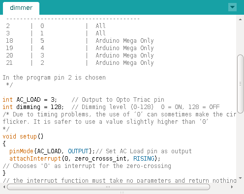
Attach the Zero cross pin of the module to Arduino External Interrupt pin
Select the correct Interrupt # from the below table
(the Pin numbers are digital pins, NOT physical pins:
digital pin 2 [INT0]=physical pin 4 and digital pin 3 [INT1]= physical pin
5)
check: interrupts
Pin | Interrrupt # | Arduino Platform
---------------------------------------
2 | 0 | All -But it is INT1 on the Leonardo
3 | 1 | All -But it is INT0 on the Leonardo
18 | 5 | Arduino Mega Only
19 | 4 | Arduino Mega Only
20 | 3 | Arduino Mega Only
21 | 2 | Arduino Mega Only
0 | 0 | Leonardo
1 | 3 | Leonardo
7 | 4 | Leonardo
Arduino Due has no standard interrupt pins as an iterrupt can be attached to
almost any pin.
In program pin 2 is chosen
=================================================================*/
/*H*****************************************************
*
*******************************************************/
// ===================== DEFINES =================================
// ===================== PROTOTYPES =================================
void zero_crosss_int();
// ===================== VARIABLES =================================
int AC_LOAD = 3; // Output to Opto Triac pin
int dimming = 128; // Dimming level (0-128) 0 = ON, 128 = OFF
/*F*****************************************************
*
*******************************************************/
void
setup()
{
pinMode( AC_LOAD, OUTPUT); // Set AC Load pin as output
// Choose zero cross interrupt # from the table above
attachInterrupt( 0, zero_crosss_int, RISING);
}
/*F*****************************************************
*
*******************************************************/
void
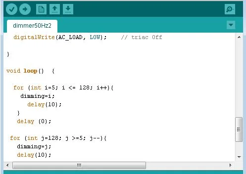
loop()
{
for( int i=5; i < 128; i++)
{
dimming=i;
delay(10);
}
}
/*F*****************************************************
* interrupt function must take no parameters and return nothing
* functo be fired at zero crossing to dim light
*******************************************************/
void
zero_crosss_int()
{
// Firing angle calculation : 1 full 50Hz wave =1/50=20ms
// Every zerocrossing thus: (50Hz)-> 10ms (1/2 Cycle)
// For 60Hz => 8.33ms (10.000/120)
// 10ms=10000us
// (10000us - 10us) / 128 = 75 (Approx) For 60Hz =>65
int dimtime = (75*dimming); // For 60Hz =>65
delayMicroseconds(dimtime); // Wait till firing the TRIAC
digitalWrite(AC_LOAD, HIGH); // Fire the TRIAC
delayMicroseconds(10); // triac On propogation delay
// (for 60Hz use 8.33) Some Triacs need a longer period
digitalWrite(AC_LOAD, LOW); // No longer trigger the TRIAC (the next
zero crossing will swith it off) TRIAC
}
About the software: theoretically in the loop you could let variable 'i'
start from '0'. However, since the timing in the interrupt is a bit of an
approximation using '0' (fully on) could screw up the timing a bit. the
same goes for 128 (Full off) though that seems to be less critical. Wether
'5' or perhaps '1' is the limit for your set up is a matter of trying,
your range may go from e.g. 2 to 126 instead of 0-128. If anybody has a
more precise way to set up the timing in the interrupt I'd be happy to
hear it.
Ofcourse it is not necessary to work with interrupts. It is also possible
to keep polling the zero crossing pin for going to 0.
Though the software works with an interrupt to determine the moment of zero
crosssing, it is still not so efficient because the time (dimtime) we need
to wait after the zero crossing before the triac is fired is literally
spent 'waiting' in the zero cross interrupt function.
It would be more efficient to set a timer interrupt to fire at the right
moment so in the mean time the arduino can do something else. Such a
program can be found in step 6
NOTE
Let me just reiterate the above statement: This program is a demo of how
you can control the dimmer. It is NOT and efficient program as it spends
most of its time waiting. It is therefore NOT the most suitable to combine
with other tasks of the processor. If you need a more efficient program
use a timer instead of delay
Step 5: Arduino Controlled Lightdimmer:
the Software II
I found another piece of Software that allows controlling the lamp via the
serial port.It triggers on the falling edge of the zero-crossing signal,
so the timing is a bit different.
I have not tested it myself yet, but I see reasons why it should not work:
as far as i can see it doesnt receive the number typed in the serial port
but it receives the ascii value of each digit that is typed, so a '0' will
be seen as 48
// ====================== DEFINES ==================================
// ====================== PROTOTYPES ==================================
// ====================== VARIABLES ==================================
int AC_pin = 3; // Pin to OptoTriac
byte dim = 0; // Initial brightness level from 0 to 255, change as you like!
/*F*****************************************************
*
*******************************************************/
void
setup()
{
Serial.begin( 9600 );
pinMode( AC_pin, OUTPUT);
// When arduino Pin 2 is FALLING from HIGH to LOW, run light procedure!
attachInterrupt( 0, light, FALLING);
}
/*F*****************************************************
*
*******************************************************/
void
light()
{
if( Serial.available() )
{
dim = Serial.read();
if( dim < 1)
{ // Turn TRIAC completely OFF if dim is 0
digitalWrite(AC_pin, LOW);
}
if( dim > 254)
{ // Turn TRIAC completely ON if dim is 255
digitalWrite( AC_pin, HIGH);
}
}
if (dim > 0 && dim < 255)
{ // Dimming part, if dim is not 0 and not 255
delayMicroseconds( 34 * (255-dim));
digitalWrite( AC_pin, HIGH );
delayMicroseconds( 500 );
digitalWrite( AC_pin, LOW);
}
}
/*F*****************************************************
*
*******************************************************/
void
loop()
{
}
Just a note: Above software is not mine. I think it is better to keep
the check of serial port out of interrupt. Also 500uS delay
before TRIAC is switched OFF is maybe a bit long.
Even more software here
Step 6: Arduino Controlled Light Dimmer:
the Software III
 Arduino Controlled Light Dimmer: the Software III
The code below uses the timer function rather than a delay and has been
confirmed to work on the Leonardo as well
/*H*****************************************************
* C Light Control
Updated by Robert Twomey
Changed zero-crossing detection to look for RISING edge rather
than falling. (originally it was only chopping the negative half
of the AC wave form).
Also changed the dim_check() to turn on the Triac, leaving it on
until the zero_cross_detect() turn's it off.
Adapted from sketch by Ryan McLaughlin
http://www.arduino.cc/cgi-bin/yabb2/YaBB.pl?num=1230333861/30
*******************************************************/
#include // from http://www.arduino.cc/playground/Code/Timer1
// ====================== DEFINES ==================================
// ====================== PROTOTYPES ==================================
// ====================== VARIABLES ==================================
volatile int i =0; // COUNTER vAR VOLATILE IN INTERRUPT
volatile boolean zero_cross=0; // BOOL CROSSED ZERO FLAG
int AC_pin = 11; // Output to Opto Triac
int dim = 0; // Dimming level (0-128) 0 = on, 128 = 0ff
int inc=1; // COUNTING UP OR DOWN, 1=UP, -1=DOWN
int freqStep = 75; // delay-per-brightness step in microseconds
// For 60 Hz it should be 65
// BASED OF YOUR AC LINE FREQ (50Hz OR 60Hz)
// AND THE NUMBER OF BRIGHTNESS STEPS YOU WANT
// Realize that there are 2 zerocrossing per cycle. This means
// zero crossing happens at 120Hz for a 60Hz supply or 100Hz for a 50Hz supply.
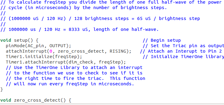
// To calculate freqStep divide the length of one full half-wave of the power
// cycle (in microseconds) by the number of brightness steps.
//
// (120 Hz=8333uS) / 128 brightness steps = 65 uS / brightness step
// (100Hz=10000uS) / 128 steps = 75uS/step
/*F*****************************************************
*
*******************************************************/
void
setup()
{
pinMode( AC_pin, OUTPUT); // SET TRIAC PIN AS OUTPUT
// ATTACH AN INTERUPT TO PIN 2 (INTERUPT 0) FOR ZERO CROSS DETECTION
attachInterrupt( 0, zero_cross_detect, RISING);
Timer1.initialize( freqStep ); // INIT TIMERONE LIB FOR FREQ NEEDED
Timer1.attachInterrupt( dim_check, freqStep );
// Use TimerOne Library to attach an interrupt
// to function we use to check to see if it is
// right time to fire triac. function
// will now run every freqStep in microseconds.
}
/*F*****************************************************
*
*******************************************************/
void
loop()
{
dim += inc;
if( (dim >= 128) || (dim<=0) )
inc*=-1;
delay( 18 );
}
/*F*****************************************************
*
*******************************************************/
void
zero_cross_detect()
{
zero_cross = true; // SET BOOL TRUE, ZERO CROSS HAS OCCURED
i =0;
digitalWrite( AC_pin, LOW ); // TURN OFF TRIAC (AND AC)
}
/*F*****************************************************
* Turn on the TRIAC at the appropriate time
*******************************************************/
void
dim_check()
{
int ndx;
if( zero_cross == true)
{
if( ndx >= dim)
{
digitalWrite( AC_pin, HIGH); // turn on light
ndx =0; // reset time step counter
zero_cross = false; //reset zero cross detection
}
else
{
ndx++; // increment time step counter
}
}
}
Arduino Controlled Light Dimmer: the Software III
The code below uses the timer function rather than a delay and has been
confirmed to work on the Leonardo as well
/*H*****************************************************
* C Light Control
Updated by Robert Twomey
Changed zero-crossing detection to look for RISING edge rather
than falling. (originally it was only chopping the negative half
of the AC wave form).
Also changed the dim_check() to turn on the Triac, leaving it on
until the zero_cross_detect() turn's it off.
Adapted from sketch by Ryan McLaughlin
http://www.arduino.cc/cgi-bin/yabb2/YaBB.pl?num=1230333861/30
*******************************************************/
#include // from http://www.arduino.cc/playground/Code/Timer1
// ====================== DEFINES ==================================
// ====================== PROTOTYPES ==================================
// ====================== VARIABLES ==================================
volatile int i =0; // COUNTER vAR VOLATILE IN INTERRUPT
volatile boolean zero_cross=0; // BOOL CROSSED ZERO FLAG
int AC_pin = 11; // Output to Opto Triac
int dim = 0; // Dimming level (0-128) 0 = on, 128 = 0ff
int inc=1; // COUNTING UP OR DOWN, 1=UP, -1=DOWN
int freqStep = 75; // delay-per-brightness step in microseconds
// For 60 Hz it should be 65
// BASED OF YOUR AC LINE FREQ (50Hz OR 60Hz)
// AND THE NUMBER OF BRIGHTNESS STEPS YOU WANT
// Realize that there are 2 zerocrossing per cycle. This means
// zero crossing happens at 120Hz for a 60Hz supply or 100Hz for a 50Hz supply.
// To calculate freqStep divide the length of one full half-wave of the power
// cycle (in microseconds) by the number of brightness steps.
//
// (120 Hz=8333uS) / 128 brightness steps = 65 uS / brightness step
// (100Hz=10000uS) / 128 steps = 75uS/step
/*F*****************************************************
*
*******************************************************/
void
setup()
{
pinMode( AC_pin, OUTPUT); // SET TRIAC PIN AS OUTPUT
// ATTACH AN INTERUPT TO PIN 2 (INTERUPT 0) FOR ZERO CROSS DETECTION
attachInterrupt( 0, zero_cross_detect, RISING);
Timer1.initialize( freqStep ); // INIT TIMERONE LIB FOR FREQ NEEDED
Timer1.attachInterrupt( dim_check, freqStep );
// Use TimerOne Library to attach an interrupt
// to function we use to check to see if it is
// right time to fire triac. function
// will now run every freqStep in microseconds.
}
/*F*****************************************************
*
*******************************************************/
void
loop()
{
dim += inc;
if( (dim >= 128) || (dim<=0) )
inc*=-1;
delay( 18 );
}
/*F*****************************************************
*
*******************************************************/
void
zero_cross_detect()
{
zero_cross = true; // SET BOOL TRUE, ZERO CROSS HAS OCCURED
i =0;
digitalWrite( AC_pin, LOW ); // TURN OFF TRIAC (AND AC)
}
/*F*****************************************************
* Turn on the TRIAC at the appropriate time
*******************************************************/
void
dim_check()
{
int ndx;
if( zero_cross == true)
{
if( ndx >= dim)
{
digitalWrite( AC_pin, HIGH); // turn on light
ndx =0; // reset time step counter
zero_cross = false; //reset zero cross detection
}
else
{
ndx++; // increment time step counter
}
}
}
Step 7: MQTT Your Dimmer
 It is possible to use MQTT to control your dimmer, provided you have a WLAN
connection. In this example I am using an Arduino UNO with Ethernetshield.
The topic is "home/br/sb" with a payload from 0-100 to set the dimming
level
/*H*****************************************************
*
*******************************************************/
#include <Ethernet.h> // Ethernet.h
#include <PubSubClient.h> // PubSubClient.h
#include <TimerOne.h> // TimerOne.h
// ========================= DEFINES ===============================
#define CLIENT_ID "Dimmer"
#define PUBLISH_DELAY 3000
// ========================= PROTOTYPES ===============================
void sendData();
void callback( char* topic, byte* payload, unsigned int length);
void zero_cross_detect();
void dim_check();
// ========================= VARIABLES ===============================
String ip = "";
bool startsend = HIGH;
uint8_t mac[6] = {0x00, 0x01, 0x02, 0x03, 0x04, 0x07};
volatile int i =0; // COUNTER, VARIABLE VOLATILE ITS AN INTERRUPT
volatile boolean zero_cross =0; // Boolean "switch" IF CROSSED ZERO
int AC_pin1 = 4; // Output to Opto Triac
int dim1 = 0; // Dimming level (0-100) 0 = on, 100 = 0ff
int inc=1; // counting up or down, 1=up, -1=down
int freqStep = 100;
EthernetClient ethClient;
PubSubClient mqttClient;
long previousMillis;
/*F*****************************************************
*
*******************************************************/
void
setup()
{
attachInterrupt( 0, zero_cross_detect, RISING);
// ATTACH INTERUPT TO PIN 2 (INTERUPT 0) FOR ZERO CROSS DETECTION
Timer1.initialize( freqStep ); // INIT TIMERoNE LIB FOR FREQ
Timer1.attachInterrupt( dim_check, freqStep);
pinMode( 4, OUTPUT);
Serial.begin( 9600 ); // SETUP SERIAL COMM
while( !Serial )
{};
Serial.println( F("dimmer"));
Serial.println();
if( Ethernet.begin(mac) == 0)
{ // SETUP ETHERNET COMMUNICATION USING DHCP
Serial.println( F( "Unable to configure Ethernet using DHCP"));
for( ; ; );
}
Serial.println( F( "Ethernet configured via DHCP"));
Serial.print( "IP address: ");
Serial.println( Ethernet.localIP());
Serial.println();
ip = String( Ethernet.localIP()[0]);
ip = ip + ".";
ip = ip + String( Ethernet.localIP()[1]);
ip = ip + ".";
ip = ip + String( Ethernet.localIP()[2]);
ip = ip + ".";
ip = ip + String( Ethernet.localIP()[3]);
//Serial.println( ip );
// setup mqtt client
mqttClient.setClient( ethClient );
// < PUT HERE ADDRESS OF MQTT SERVER
mqttClient.setServer( "192.168.1.103", 1883);
//Serial.println(F( "MQTT client configured"));
mqttClient.setCallback( callback );
Serial.println();
Serial.println( F( "Ready to send data"));
previousMillis = millis();
mqttClient.publish( "home/br/nb/ip", ip.c_str());
}
/*F*****************************************************
* IT'S TIME TO SEND NEW DATA?
*******************************************************/
void
loop()
{
if( millis() - previousMillis > PUBLISH_DELAY)
{
sendData();
previousMillis = millis();
}
mqttClient.loop();
Serial.print( "dim1 = " );
Serial.println( dim1 );
}
/*F*****************************************************
*
*******************************************************/
void
sendData()
{
char msgBuffer[20];
if( mqttClient.connect( CLIENT_ID) )
{
mqttClient.subscribe( "home/br/sb");
if( startsend )
{
mqttClient.publish( "home/br/nb/ip", ip.c_str());
startsend = LOW;
}
}
}
/*F*****************************************************
*
*******************************************************/
void
callback( char* topic, byte* payload, unsigned int length)
{
int ndx;
char msgBuffer[20];
payload[length] = '\0'; // TERMINATE STRING WITH '0'
String strPayload = String( (char*)payload ); // CONVERT TO STRING
Serial.print( "strPayload = " );
Serial.println( strPayload ); // USE IF USING LONGER SOUTHBOUND TOPICS
Serial.print( "Message arrived [" );
Serial.print( topic );
Serial.print( "] " ); // MQTT_BROKER
for( ndx = 0; i < length; ndx++)
{
Serial.print( (char)payload[ndx]);
}
Serial.println();
Serial.println( payload[0] );
dim1 = strPayload.toInt();
}
/*F*****************************************************
*
*******************************************************/
void
zero_cross_detect()
{
zero_cross = true; // SET BOOL TRUE, TELL DIMMING FUNC ZERO CROSS OCCURED
i =0;
digitalWrite( AC_pin1, LOW); // turn off TRIAC (and AC)
}
/*F*****************************************************
* Turn on the TRIAC at the appropriate time
*******************************************************/
void
dim_check()
{
if( zero_cross == true )
{
if( i i>= dim1)
{
digitalWrite( AC_pin1, HIGH); // turn on light
i =0; // reset time step counter
zero_cross = false; //reset zero cross detection
}
else
{
i++; // increment time step counter
}
}
}
It is possible to use MQTT to control your dimmer, provided you have a WLAN
connection. In this example I am using an Arduino UNO with Ethernetshield.
The topic is "home/br/sb" with a payload from 0-100 to set the dimming
level
/*H*****************************************************
*
*******************************************************/
#include <Ethernet.h> // Ethernet.h
#include <PubSubClient.h> // PubSubClient.h
#include <TimerOne.h> // TimerOne.h
// ========================= DEFINES ===============================
#define CLIENT_ID "Dimmer"
#define PUBLISH_DELAY 3000
// ========================= PROTOTYPES ===============================
void sendData();
void callback( char* topic, byte* payload, unsigned int length);
void zero_cross_detect();
void dim_check();
// ========================= VARIABLES ===============================
String ip = "";
bool startsend = HIGH;
uint8_t mac[6] = {0x00, 0x01, 0x02, 0x03, 0x04, 0x07};
volatile int i =0; // COUNTER, VARIABLE VOLATILE ITS AN INTERRUPT
volatile boolean zero_cross =0; // Boolean "switch" IF CROSSED ZERO
int AC_pin1 = 4; // Output to Opto Triac
int dim1 = 0; // Dimming level (0-100) 0 = on, 100 = 0ff
int inc=1; // counting up or down, 1=up, -1=down
int freqStep = 100;
EthernetClient ethClient;
PubSubClient mqttClient;
long previousMillis;
/*F*****************************************************
*
*******************************************************/
void
setup()
{
attachInterrupt( 0, zero_cross_detect, RISING);
// ATTACH INTERUPT TO PIN 2 (INTERUPT 0) FOR ZERO CROSS DETECTION
Timer1.initialize( freqStep ); // INIT TIMERoNE LIB FOR FREQ
Timer1.attachInterrupt( dim_check, freqStep);
pinMode( 4, OUTPUT);
Serial.begin( 9600 ); // SETUP SERIAL COMM
while( !Serial )
{};
Serial.println( F("dimmer"));
Serial.println();
if( Ethernet.begin(mac) == 0)
{ // SETUP ETHERNET COMMUNICATION USING DHCP
Serial.println( F( "Unable to configure Ethernet using DHCP"));
for( ; ; );
}
Serial.println( F( "Ethernet configured via DHCP"));
Serial.print( "IP address: ");
Serial.println( Ethernet.localIP());
Serial.println();
ip = String( Ethernet.localIP()[0]);
ip = ip + ".";
ip = ip + String( Ethernet.localIP()[1]);
ip = ip + ".";
ip = ip + String( Ethernet.localIP()[2]);
ip = ip + ".";
ip = ip + String( Ethernet.localIP()[3]);
//Serial.println( ip );
// setup mqtt client
mqttClient.setClient( ethClient );
// < PUT HERE ADDRESS OF MQTT SERVER
mqttClient.setServer( "192.168.1.103", 1883);
//Serial.println(F( "MQTT client configured"));
mqttClient.setCallback( callback );
Serial.println();
Serial.println( F( "Ready to send data"));
previousMillis = millis();
mqttClient.publish( "home/br/nb/ip", ip.c_str());
}
/*F*****************************************************
* IT'S TIME TO SEND NEW DATA?
*******************************************************/
void
loop()
{
if( millis() - previousMillis > PUBLISH_DELAY)
{
sendData();
previousMillis = millis();
}
mqttClient.loop();
Serial.print( "dim1 = " );
Serial.println( dim1 );
}
/*F*****************************************************
*
*******************************************************/
void
sendData()
{
char msgBuffer[20];
if( mqttClient.connect( CLIENT_ID) )
{
mqttClient.subscribe( "home/br/sb");
if( startsend )
{
mqttClient.publish( "home/br/nb/ip", ip.c_str());
startsend = LOW;
}
}
}
/*F*****************************************************
*
*******************************************************/
void
callback( char* topic, byte* payload, unsigned int length)
{
int ndx;
char msgBuffer[20];
payload[length] = '\0'; // TERMINATE STRING WITH '0'
String strPayload = String( (char*)payload ); // CONVERT TO STRING
Serial.print( "strPayload = " );
Serial.println( strPayload ); // USE IF USING LONGER SOUTHBOUND TOPICS
Serial.print( "Message arrived [" );
Serial.print( topic );
Serial.print( "] " ); // MQTT_BROKER
for( ndx = 0; i < length; ndx++)
{
Serial.print( (char)payload[ndx]);
}
Serial.println();
Serial.println( payload[0] );
dim1 = strPayload.toInt();
}
/*F*****************************************************
*
*******************************************************/
void
zero_cross_detect()
{
zero_cross = true; // SET BOOL TRUE, TELL DIMMING FUNC ZERO CROSS OCCURED
i =0;
digitalWrite( AC_pin1, LOW); // turn off TRIAC (and AC)
}
/*F*****************************************************
* Turn on the TRIAC at the appropriate time
*******************************************************/
void
dim_check()
{
if( zero_cross == true )
{
if( i i>= dim1)
{
digitalWrite( AC_pin1, HIGH); // turn on light
i =0; // reset time step counter
zero_cross = false; //reset zero cross detection
}
else
{
i++; // increment time step counter
}
}
}
Step 8: Software to Set Level Using Up
and Down Buttons
Below a code to set the light level with up and down buttons. It uses a
timer that checks for the time necessary to trigger the TRIAC, rather than
wait in a delay loop
/*H*****************************************************
* AC Light Control
Uses up and down buttons to set levels
makes use of a timer interrupt to set the level of dimming
*******************************************************/
#include <TimerOne.h>
// From: http://www.arduino.cc/playground/Code/Timer1
// ==================== DEFINES ==================================
// ==================== PROTOTYPES ==================================
void zero_cross_detect();
void dim_check();
// ==================== VARIABLES ==================================
volatile int i =0;// DIMMING STEPS COUNTER VOLATILE, PASSED BETWEEN INTERRUPTS
volatile boolean zero_cross=0; // CROSSED ZERO FLAG
int AC_pin = 3; // OPTO TRIAC OUTPUT
int buton1 = 4; // PIN 4 1ST BUTTON
int buton2 = 5; // PIN 5 2nd BUTTON
int dim2 = 0; // LED CONTROL
int dim = 128; // DIMMING LEVEL (0-128) 0 = ON, 128 = 0FF
int pas = 8; // COUNT STEP
int freqStep = 75; // delay-per-brightness STEP US, 128 STEPS
// SET IF 60 Hz GRID FREQUENCY 65
/*F*****************************************************
*
*******************************************************/
void
setup()
{ // Begin setup
Serial.begin( 9600 );
pinMode( buton1, INPUT); // SET BUTON1 PIN AS INPUT
pinMode( buton2, INPUT); // SET BUTON2 PIN AS INPUT
pinMode( AC_pin, OUTPUT); // SET TRIAC PIN OUTPUT
attachInterrupt( 0, zero_cross_detect, RISING); // ATTACH AN INTERUPT
to Pin 2 ( interupt 0) for Zero Cross Detection
Timer1.initialize( freqStep ); // INIT TIMERONE LIB FOR FREQ
Timer1.attachInterrupt( dim_check, freqStep );
// GO TO DIM_CHECK PROCEDURE EVERY 75 US (50Hz) or 65 uS (60Hz)
// USE TIMERONE LIB FOR INTERRUPT
}
/*F*****************************************************
*
*******************************************************/
void
loop()
{
digitalWrite( buton1, HIGH );
digitalWrite( buton2, HIGH );
if( digitalRead( buton1 ) == LOW)
{
if( dim < 127)
{
dim = dim + pas;
if( dim < 127)
{
dim =128;
}
}
}
if( digitalRead( buton2 ) == LOW)
{
if( dim > 5 )
{
dim = dim - pas;
if( dim < 0)
{
dim =0;
}
}
}
while (digitalRead(buton1) == LOW) { }
delay(10); // waiting little bit...
while (digitalRead(buton2) == LOW) { }
delay(10); // waiting little bit...
dim2 = 255 -2 * dim;
if( dim2<0)
{
dim2 = 0;
}
Serial.print( "dim=" );
Serial.print( dim );
Serial.print(" dim2=");
Serial.print( dim2 );
Serial.print( " dim1=");
Serial.print( 2 * dim);
Serial.print( '\n' );
delay( 100 );
}
/*F*****************************************************
*
*******************************************************/
void
zero_cross_detect()
{
zero_cross = true; // dim_check FUNC ZERO CROSS HAS OCCURED
i =0; // STEPCOUNTER TO 0.... AS START NEW CYCLE
digitalWrite( AC_pin, LOW);
}
/*F*****************************************************
* EVERY 75 (65) uS TURN ON TRIAC AT APPROPRIATE TIME
* First check if a flag has been set
* Then check if the counter 'i' has reached the dimming level
* if so.... switch on the TRIAC and reset the counter
*******************************************************/
void
dim_check()
{
if( zero_cross == true)
{
if( i &gr;= dim )
{
digitalWrite( AC_pin, HIGH); // turn on light
i =0; // reset time step counter
zero_cross =false; // reset zero cross detection flag
}
else
{
i++; // increment time step counter
}
}
}
Step 9: More Interrupt Driven Software
// AC dimmer
// The hardware timer runs at 16MHz. Using a
// divide by 256 on the counter each count is
// 16 microseconds. 1/2 wave of a 60Hz AC signal
// is about 520 counts (8,333 miliseconds).
// 1/2 wave of a 50 Hz signal is 625 counts
/*H*****************************************************************
Pin | Interrrupt # | Arduino Platform
---------------------------------------
2 | 0 | All -But it is INT1 on the Leonardo
3 | 1 | All -But it is INT0 on the Leonardo
18 | 5 | Arduino Mega Only
19 | 4 | Arduino Mega Only
20 | 3 | Arduino Mega Only
21 | 2 | Arduino Mega Only
0 | 0 | Leonardo
1 | 3 | Leonardo
7 | 4 | Leonardo
The Arduino Due has no standard interrupt pins as an iterrupt can be attached
to almosty any pin.
In the program pin 2 is chosen
******************************************************************/
#include
#include
// =================== DEFINES =====================================
#define ZEROCROSS 2 // zero cross detect
#define TRIAC 3 // triac gate
#define PULSE 4 // trigger pulse width (counts)
// =================== PROTOTYPES =====================================
void zeroCrossingInterrupt();
ISR( TIMER1_COMPA_vect);
ISR( TIMER1_OVF_vect );
// =================== VARIABLES =====================================
int dim=483;
/*F*****************************************************
*
*******************************************************/
void
setup()
{
pinMode( ZEROCROSS, INPUT); // zero cross detect
digitalWrite( ZEROCROSS, HIGH); // enable pull-up resistor
pinMode( TRIAC, OUTPUT); // triac gate control
// set up Timer1 (see ATMEGA 328 data sheet pg 134
OCR1A = 100; // initialize comparator compared with TCNT1
TIMSK1 = 0x03; // enable comparator A and overflow interrupts
// 0x03=0b11 =OCIE1A and TOIE1
// OCIE1A Timer/Counter1 Output Compare A Match interrupt enable. Interrupt set
// TOIE1 Timer/Counter1 Overflow interrupt is enabled.
TCCR1A = 0x00; // timer control registers set for
TCCR1B = 0x00; // normal operation, timer disabled
// set up zero crossing interrupt
attachInterrupt(0,zeroCrossingInterrupt, RISING);
}
/*F*****************************************************
*
*******************************************************/
void
loop()
{
dim--;
OCR1A = i;// set compare register brightness desired. delay to on value
if( dim < 65)
{
dim =483;
} // 1 msec tot 7.726 msec
delay(15);
}
/*F*****************************************************
* Interrupt Service Routines
*******************************************************/
void
zeroCrossingInterrupt()
{
TCCR1B=0x04; //start timer with divide by 256 input 16us tics 4=0b100 =CS12:1, CS11:0, CS10:0 table 16.5
TCNT1 = 0; //reset timer - count from zero
}
/*F*****************************************************
*comparator match. overflow werd bereikt als de waarde van 'i' wordt gematched
*******************************************************/
ISR( TIMER1_COMPA_vect)
{
digitalWrite( TRIAC, HIGH ); // Triac will be set high
TCNT1 = 65536-PULSE; // trigger pulse width telt 4 periodes van 16uS
}
/*F*****************************************************
*
*******************************************************/
ISR( TIMER1_OVF_vect )
{ // timer1 overflow wordt bereikt na 4x16us
digitalWrite( TRIAC, LOW ); // turn off triac gate
TCCR1B = 0x00; // disable timer stopd unintended triggers
}
Step 10: Arduino Controlled Lightdimmer:
Result & Expansion
Just a quick cellphone recorded video of it's workings
3 channels
This circuit can also be used for an RGB mixer, albeit you need two
additional TRIAC circuits. You could use this circuit+PCB in duplo for
that, but make sure you use a random cycle opto-coupler suah as the
MOC3021. Do not use a zerocrossing Opto-coupler such as the MOC3041.
I now made a 3 channel Ibble
The zero-crossing circuit is ofcourse only needed once.
Perhaps this is still something for tradition (call it Old fashioned):
x-mas tree lights that work directly on 220 (or 110) Volts. Hang 3
different color lamp strings in the tree and regulate them with this
circuit expanded with two TRIAC circuits
Frequency
Depending on the grid frequency (either 50 or 60) different step values
need to be set manually. However, it is possible to let the software
determine the frequency in a setup routine, e.g. by meauring the time
between two zero crossings or count the number of zerocriossings within a
set time.
Step 11: 8051 Controlled Lightdimmer: Software
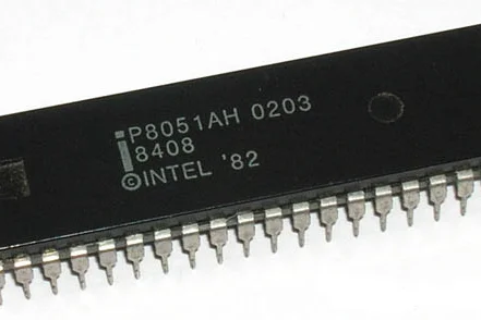 8051 Controlled Lightdimmer: Software
Obviously, one can use the 8051 microcontroller series as well to control
the dimmer.
As I dont have an 8051 development system anymore, I cannot test any code,
but should you want to develop this for an 8051, the following example may
be of help:
/*H*****************************************************
* Controlling AC with a 8051
* Untested Code
* Compiles with MicroC Pro for 8051
*******************************************************/
int dimming;
int x;
int i;
/*F*****************************************************
*
*******************************************************/
void
ex0_isr( void )
iv IVT_ADDR_EX0 ilevel 0 ics ICS_AUTO
{
/*===================================================*/
int dimtime = (75 * dimming );
//delay_us( dimtime );
P0 = 0xFF; // sets entire PORT 0 high, can also use e.g. P0_1 =1 ;
delay_us( 10 ); // propagationdelay
P0 = 0x00;
}
/*F*****************************************************
*
*******************************************************/
void
delay( int maal )
{
for( x=1; x< maal; x++)
{
delay_us(75); // 65 for 60Hz
}
}
/*F*****************************************************
*
*******************************************************/
void
main()
{
/*------------------------
Configure INT0 (external interrupt 0) to generate
an interrupt on the falling-edge of /INT0 (P3.2).
Enable the EX0 interrupt and then enable the
global interrupt flag.
------------------------------------------------*/
IT0_bit =1; // Configure interrupt 0 for falling edge on /INT0 (P3.2)
EX0_bit = 1; // Enable EX0 Interrupt
EA_bit = 1; // Enable Global Interrupt Flag
P0 = 0x00; //all pin of PORT0 declared as output
while( 1 )
{
for( i =5; i< 128; i++)
{
dimming =i;
delay( 10 ); //arbitrary delay between steps
}
}
}
I cannot garantee this code to work as I have no way of testing it. Should
anybody try it and have results I would be glad to hear it.
An application note describing a fan control according to the same
principle, can be found here.
8051 Controlled Lightdimmer: Software
Obviously, one can use the 8051 microcontroller series as well to control
the dimmer.
As I dont have an 8051 development system anymore, I cannot test any code,
but should you want to develop this for an 8051, the following example may
be of help:
/*H*****************************************************
* Controlling AC with a 8051
* Untested Code
* Compiles with MicroC Pro for 8051
*******************************************************/
int dimming;
int x;
int i;
/*F*****************************************************
*
*******************************************************/
void
ex0_isr( void )
iv IVT_ADDR_EX0 ilevel 0 ics ICS_AUTO
{
/*===================================================*/
int dimtime = (75 * dimming );
//delay_us( dimtime );
P0 = 0xFF; // sets entire PORT 0 high, can also use e.g. P0_1 =1 ;
delay_us( 10 ); // propagationdelay
P0 = 0x00;
}
/*F*****************************************************
*
*******************************************************/
void
delay( int maal )
{
for( x=1; x< maal; x++)
{
delay_us(75); // 65 for 60Hz
}
}
/*F*****************************************************
*
*******************************************************/
void
main()
{
/*------------------------
Configure INT0 (external interrupt 0) to generate
an interrupt on the falling-edge of /INT0 (P3.2).
Enable the EX0 interrupt and then enable the
global interrupt flag.
------------------------------------------------*/
IT0_bit =1; // Configure interrupt 0 for falling edge on /INT0 (P3.2)
EX0_bit = 1; // Enable EX0 Interrupt
EA_bit = 1; // Enable Global Interrupt Flag
P0 = 0x00; //all pin of PORT0 declared as output
while( 1 )
{
for( i =5; i< 128; i++)
{
dimming =i;
delay( 10 ); //arbitrary delay between steps
}
}
}
I cannot garantee this code to work as I have no way of testing it. Should
anybody try it and have results I would be glad to hear it.
An application note describing a fan control according to the same
principle, can be found here.
Step 12: PIC Controlled Lightdimmer: the Software
PIC Controlled Lightdimmer: the Software
If you want to use this circuit with a PIC microcontroller, the software in
this link may help you get further:
http://www.edaboard.com/thread265546.html
A good article on zero crossing detection with a PIC can be found here:
http://tahmidmc.blogspot.nl/2012/10/zero-crossing-...
The writer Syed Tahmid Mahbub gives a basic program that detects the zero
crossing and then triggers the LED with a delay of 20ms .
Although I never worked with PIC's before and am no crack on C programming.
I decided to see if i could build on his program and make it possible to
vary the light intensity, rather than just give it one value (the 20ms
delay).
I soon found out that the delay_ms and delay_us functions in C, are a bit
tricky, namely that they don’t accept a variable. The delay time needs
to be known at the time of compilation as it is hard coded. I saw some
complicated work-arounds, but I thought a simpler solution would be to
make a function that gives a 75 uS delay (make that 65 for 60Hz) and call
that with a parameter determining how often that delay is looped.
The maximum number of times the delay is looped is 128. That is because I
have randomly chosen that the light should be dimmed in 128 steps (with 0
being full on and 128 being off).
A warning though: I have no PIC programmer and I am not planning (yet) to
go into pics, happy as I am with the Atmega and Attiny series. Therefore I
cannot test the program. I can only say that it compiles without problems,
and if you want to use the circuit on a PIC, it will help you get started.
You can also find full projects, including a program, here and here,
including an IR remoteand here
/*F*****************************************************
* Programmer: DIY_Bloke
* Strongly based on a 0-X program from Syed Tahmid Mahbub
* Compiler: mikroC PRO for PIC v4.60
* Target PIC: PIC16F877A
* Program for phase angle control
* zero crossing signal on pin 33 RB0/INT
* gating signal to MOC3021 via 220-470R from pin 19 RD0/PSP0
* X-tal 4 MHz
*******************************************************/
// ========================= DEFINES ===============================
// ========================= PROTOTYPES ===============================
// ========================= VARIABLES ===============================
unsigned char FlagReg;
int x;
int maal;
int dimming=20;// '20' is just an example. Dimming should contain a
// value between 0 and 128 and can be taken from e.g. a
// variable resistor or LDR or a value coming out of a program
sbit ZC at FlagReg.B0;
/*F*****************************************************
*
*******************************************************/
void
interrupt()
{
if( INTCON.INTF )
{ //INTF flag raised, so external interrupt occured
ZC = 1;
INTCON.INTF = 0;
}
}
/*F*****************************************************
*
*******************************************************/
void
delay( int maal )
{
for( x =1; x< maal; x++)
{
delay_us( 75 ); // 65 for 60Hz
}
}
/*F*****************************************************
*
*******************************************************/
void
main()
{
PORTB = 0;
TRISB = 0x01; //RB0 input for interrupt
PORTA = 0;
ADCON1 = 7; //Disable ADC
TRISA = 0xFF; //Make all PORTA inputs
PORTD = 0;
TRISD = 0; //PORTD all output
OPTION_REG.INTEDG = 0; //interrupt on falling edge
INTCON.INTF = 0; //clear interrupt flag
INTCON.INTE = 1; //enable external interrupt
INTCON.GIE = 1; //enable global interrupt
while( 1 )
{
if( ZC )
{ //zero crossing occurred
delay( dimming ); // '20' is an example
PORTD.B0 = 1; // Send a pulse
delay_us( 250 );
PORTD.B0 = 0;
ZC = 0;
}
}
}
Step 13: Problems
Problems
If for whatever reason the circuit you built is not working, other than it
starting to smoke.
Before you do any work on the circuit UNPLUG IT FROM THE MAINS!!
There are mainly 3 things that can happen:
1-The lamp is flickering
This is probably the most common problem you can encounter and there maybe
several reasons for it e.g.
-a 'dirty' powersupply.
If your powersupply gives off a lot of extra spikes, these can be present
on the 0X signal pin and mess up the clean Zero crossing signals. Try
another powersupply.
-'timing' problems
using an optocoupler gives a precise zero-crossing signal, but it is not
extremely narrow. The pulse width of this circuit (at 50Hz) is typically
around 600us (0.6ms) which sounds fast enough. The problem is that at 50Hz
each half cycle takes only 10ms (8.33ms at 60Hz), so the pulse width is
over 5% of the total period. This is why most dimmers can only claim a
range of 10%-90% - the zero crossing pulse lasts too long to allow more
range. The solution is to avoid regulating all the way down or all the way
up. Also increasing or sometimes decreasing the step-value (the number 75
for 50Hz and 65 for 60Hz) may cure that.
2-The lamp is constantly on
This might be a software or a hardware problem and the easiest way to sort
that out is to make sure the microcontroller is not connected to the
circuit. If the lamp is still on there are grossly 4 possibilities:
- -You somehow fucked up the circuit, check if it is indeed OK and that
everything is connected to where it shoudl be connected.
- -The MOC3021 is somehow receiving a positive input, make sure there are no
stray drops of solder shorting things that shouldn’t be shorted. Short
the input and ground wire and see if the lamp stays off.
- -The MOC3021 is short circuited at the high voltage end. Remove the MOC3021
from its socket and see what happens: if yr lamp stays off there is likely
something wrong with yr MOC3021. If your lamp stays on, you probably have
a faulty TRIAC
- -You have a faulty TRIAC. As described above. Yet, check the gate resistor
if it really has the correct value, just to make sure
3-The lamp is constantly off
As this may also be a software or hardware problem, first see what hapens
with the arduino disconnected.
Connect the input to a plus 5Volt supply and measure the voltage on the
primary side of the optocoupler (YOUR CIRCUIT SHOULD NOT BE CONNECTED TO
THE MAINS). If that is a couple of volts, connect your circuit to the
mains and see what happens. If the lamp switches on there is a problem
with the input signal. If it stays off, you may have a faulty optocoupler,
a faulty TRIAC or your circuit somehow is not connected to the mains.
Another possibility is that the voltage drop over the LED is preventing
the optocoupler to open, especially when you are using say 3.3 V as a
driving voltage. Make sure you have an LED with a low voltage drop or
replace it by a wire bridge.
A piece of code that can help you test the Triac circuit is to add the
following into the setup
/*F*****************************************************
*
*******************************************************/
void
setup()
{
pinMode( AC_LOAD, OUTPUT); // Set the AC Load as output
for( int i =0; i < 10; i++)
{
digitalWrite( AC_LOAD, HIGH); // triac firing
delay( 1000 );
digitalWrite( AC_LOAD, LOW); // triac Off
delay( 1000 );
}
}
This will first fire the TRIAC a few times so you can see it is working
Most common fault till now
From all the people that contacted me about problems of the circuit not
working, the most common fault was: faulty wiring: a chip put upside down,
a solder joint not good, a wire not connected right.
Step 14: The Gate Resistor:
When cruising the internet for Triac switches, you may have come across a large
diversion in the value of the gate resistor value. My choice usually is to take
the lowest value that will still protect the gate and the optocoupler.
Reader Mali Lagunas did some research in the theory behind the criteria to
choose the value of the gate resistor. Which i will copy below:
The resistor when placed in this circuit, will have two main effects:
a) It will limit/provide the current going into the gate of the triac (I_{GT})
b) It will cause the voltage to drop when the triac is on (V_R)
The lowest value this resistor may have (for 220 V AC) is
R=220*sqrt(2)/I_{TMS}, where I_{TMS} is the maximum peak current allowed
in the photocoupler’s phototriac. These are surge values, thus they are
transient and account for a limit before breakdown. Therefore in your
circuit R would be R=220*sqrt(2)/1=311.12 or 330 ohms, since the
MOC3021′s I_{TMS}=1A. This is consistent with I_{GM} which is the peak
gate current of the TIC206. In your schematic you use 1K which would limit
the current to 311mA.
This “surge” case may take place only when a pulse is received by the
phototriac and it is able to conduct I_{GT}, and of course for a line
value of 220*sqrt(2). Charge will then accumulate in the triac’s gate
until V_{GT} gets build up and the the triac gets activated.
In quadrant I, ( V_{GT} and A1 are more positive than A2) in order for
sufficient charge to build up and V_{GT} in the main triac to bee reached,
the voltage across the triac must equal V_R+V_{TM}+V_{GT}
Of course V_R=I_{GT}*R . Commonly, V_{TM}+V_{GT} will both account for
approximately 3V (datasheet). At the same time, the resistor must provide
sufficient current to the Triac’s gate, let’s say a minimum of 25 mA
(sensitivity of the Triac), thus
V_{triac}= 330ohms*25mA+1.3V+1.1V=10.65V and
V_{triac}= 1k-ohms*25mA+1.3V+1.1V=27.4V (the value in your circuit)
Which is the voltage needed to activate the triac. Therefore, the smaller
the resistor the less voltage is required to switch on the main triac.
What goes on afterwards is mainly that there is a voltage drop across A1
and A2 and therefore the phototriac voltage and current will drop causing
turn-off state (of the phototriac). The main triac will be kept switched
on if the holding current I_H is respected. When the load current is below
I_H, the main triac is switched off until a pulse from the photodiode is
emitted again in order to polarize V_{GT} and build the required charge in
the next cycle. Q1 and Q3 are the quadrants for this setup.
Step 15: Dimming: a Bit of Theory
Just as a background to this instructable: There are various types of
dimmers. What is presented here is a phase-controlled (aka 'phase-cut')
leading edge (aka "forward phase")TRIAC dimmer.
Leading Edge Dimmers
In this type the dimmer actually cuts parts off the beginning of the
sinewave. This is the most widely used type of dimmer as it is ver
suitable for TRIACs. After all, A Triac is easy to switch on and it will
switch off by itself once there is a zero crossing because the current
drops below the gate hold current
Trailing Edge Dimmers
Also known as 'reverse phase control' dimmers. A trailing edge dimmer is a
considerably more complex circuit. The simple circuitry that is common
with leading edge types can no longer be used, because most TRIACs cannot
be turned off. Gate turn-off (GTO) TRIACs exist, but are far more
expensive and less common in the relatively small sizes needed for
lighting. To be able to implement a trailing edge dimmer, the switching
device must turn on as the AC waveform passes through zero, using a
circuit called a zero-crossing detector. After a predetermined time set by
the control, the switching device is turned off, and the remaining part of
the waveform is not used by the load.
Trailing edge dimmers commonly use a MOSFET, as these require almost no
control current and are rugged and reliable. They are also relatively
cheap and readily available at voltage ratings suitable for mains
operation. Another option is to use an IGBT (insulated gate bipolar
transistor), which combines the advantages of both MOSFET and bipolar
transistor. These are generally more expensive than MOSFETs. Again, the
waveform is ideal, and it is obvious from the actual waveform shown in
Figure 9 that there is a significant deviation - especially at full power.
This is caused because some of the applied voltage will always be lost
because the complex electronics require some voltage to operate.
Most trailing edge dimmers have another useful function - at least when
used with incandescent lamps. The circuitry is designed to provide a 'soft
start', increasing the voltage to the lamp relatively slowly. With
incandescent lamps, this almost eliminates 'thermal shock' - that brief
period at switch-on where the lamp draws around 10 times the normal
operating current. Thermal shock is responsible for most early lamp
failures - it is rare indeed for any incandescent lamp to fail while it's
on. Failure is almost always at the moment the switch is turned on. By
including the soft-start feature lamp life is increased.
Step 16: Zero Crossing: a Bit of Theory
Zero Crossing: a Bit of Theory
Though I described the zerocrossing already, I will spend some more words on it.
With the 'bridge and opto-coupler' circuit that I used in this project, the
principle is very clear: A mains AC voltage passes through 2 resistors of
33k and is rectified by the diode bridge.
This rectification results in a pulsating DC voltage that keeps the
optocoupler open, keeping the zerocrossing signal LOW till the voltage
drops to 'zero' at what point the optocoupler will not be in conduction
anymore and the zerocrossing signal is pulled high, untill the voltage
rises again enough to send the optocoupler into conduction again,
resulting in the zerocrossing pin going LOW.
The 'quality' of that zerocrossing pulse is of course depending on a number
of factors but mainly on the speed of the optocoupler, the value of the
collector resistor, but not in the least on the value of the two resistors
in the mains line.
If that value is too low, your optocoupler will burn out, but if it is too
high, the voltage at which there still is enough current going through the
optocoupler to keep it conducting becomes higher and higher. That means
that if the resistor value is too high, the switching of the optocoupler
will happen higher on the rising and descending flank of the sin wave,
resulting in a wide zerocrossing signal, that starts way before the actual
zerocrossing until way after the zerocrossing.
Ergo: The resistor value should be as low as possible. In practice however
I found the 2x 33k to be a good value, leading to a pulse starting abt
200uS before the actual zerocrossing. That is very acceptable. The current
through the 4N25 is approximately 3.33 mA. Surely we could take that up a
notch, but it isn't necessary. With these values the idle use of this
circuit is an estimated 0.7 Watts
The same actually goes for the circuit with the H11AA1. The advantage of
the H11AA1 is that one doesn't need a diode bridge as it has two
antiparallel diodes. The same goes for the IL250 series or the LTV814
One can reach the same effect with two regular optocouplers such as the
4N25, as the figure shows or with a dual optocoupler.
I also provided a circuit in which the width of the zerocrossing pulse can
be regulated.
As said before, the width of the Zerocrossing signal determines how far
before the actual zerocrossing the interrupt is generated. Ideally, if you
know how wide your zerocrossing signal is, you could take that into
account in the software. Suppose your signal is 600uS wide and suppose
that is a evenly divided timing. Then you know that your interrupt is
generated some 300uS before the actual Zerocrossing. You could wait that
period after each interrupt to get a more precise handling of the
zerocrossing
A big problem with these algorithms is that nobody accounts for the
non-linearity of this method.
Blue: 0 to 100%, Red: Watts read, yellow: the values if they are linear.
Clipboard-20240106.png
Avatar image of onolox
for 5V arduino you need to change the R3 to 10k, that results in a 4.7v signal.
For 3.3V boards it needs to be 1k to generate 3.3V signal.
Avatar image of 2019ee7 2019ee7
Hey, this doesn't work if I use esp32 board and burn the code using arduino ide.
The AC frequency where I live is 50Hz. and I am using esp32WROOMD
here is my code for esp32
/*H*****************************************************
*
*******************************************************/
#include <Arduino.h>
// ======================= DEFINES ==================================
#define ZC_PIN GPIO_NUM_12
#define SIGNAL_PIN GPIO_NUM_26
// ======================= PROTOTYPES ==================================
void zero_cross();
// ======================= VARIABLES ==================================
int dimming = 128;
/*F*****************************************************
*
*******************************************************/
void
setup()
{
pinMode( SIGNAL_PIN, OUTPUT);
attachInterrupt( digitalPinToInterrupt( ZC_PIN), zero_cross, FALLING);
}
/*F*****************************************************
*
*******************************************************/
void
loop()
{
for( int i = 5; i <= 128; i++)
{
dimming = i;
delay(10);
}
}
/*F*****************************************************
*
*******************************************************/
void
zero_cross()
{
int dimtime = (75 * dimming);
delayMicroseconds( dimtime ); // Off cycle
digitalWrite( SIGNAL_PIN, HIGH);
delayMicroseconds( 10 ); // triac On propagation delay
digitalWrite( SIGNAL_PIN, LOW ); // triac Off
}
the Triac model I am using is this:
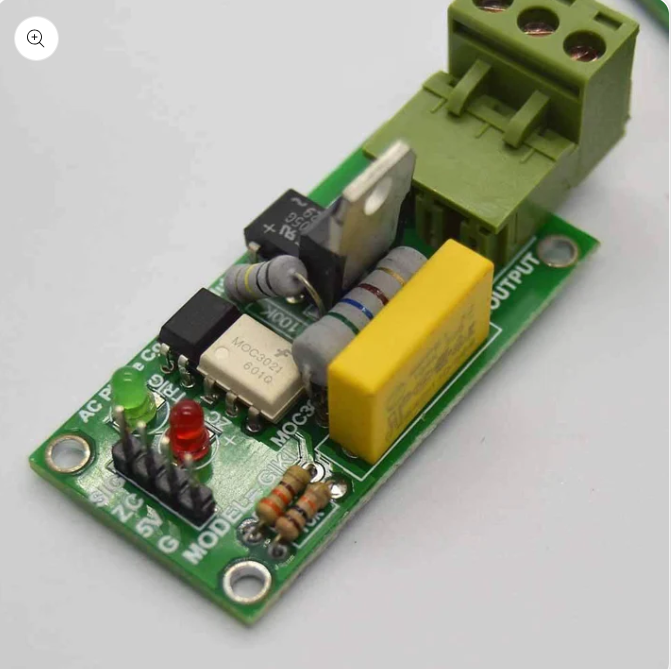 Screenshot_2.png
Avatar image of kack_in_black
kack_in_black
a year ago
Flag
WARNING:
The sketch in step 2 is wrong, you're supposed to feed the driver
(MOC3021) the mains voltage through the 1k resistor. Just connect its pin 6
(resistor pin) to transistor's mains pin instead of load pin and you're good
to go. See schematic here:
http://arduinotehniq.blogspot.com/2014/10/ac-light-dimmer-with-arduino.html
Avatar image of mgh1412
mgh1412
2 years ago
Flag
Hello
Thank you for your explanation
I wanted to use this circuit for a universal vacuum cleaner motor that the
intensity changes with the potentiometer
But before that, I connected the circuit to the lamp, and the lamp flickers
a little irregularly
For the 5V power supply, I once used Hi-link HLK(0.6A) and another time
from the laptop USB, which did not make a difference
Of course, I have used MOC3023 instead of MOC3021
Does this flickering damage the vacuum cleaner motor?
Do you have a solution to make it disappear?
Avatar image of sheminasalam
sheminasalam
3 years ago
Flag
Is it possible to use this with esphome or tasmota? I have seen that
esphome supports the similar robotdyn
dimmer.https://www.aliexpress.com/item/32802025086.html
Avatar image of AmirT11
AmirT11
6 years ago
Flag
Hello bloke
Thank you for you great project
i made it with arduino . now i wont to use esp8266
while compiling the code i faced this error...
and i download meny arduino ide versions . so can you help me
Untitled.png
ds.png
2 replies
Avatar image of vander areosa
vander areosa
3 years ago
Flag
Perfect example. I did with esp32-c3 (new one) I just needed to change the
attachInterrupt to GPIO 2 like that (2, zero_crosss_int, RISING) and
worked beautifully. congratulations for the great job. I thanks for this.
1 reply
Avatar image of najeeb53fattah
najeeb53fattah
3 years ago
Flag
After I wrote this program on my laptop and try to down loose it on my nano
arduino cat thi er was an error in the void and I don’t understand wat
is the reason
Avatar image of najeeb53fattah
najeeb53fattah
3 years ago
Flag
Can I gate the circuit digram for set up down buttons Arduino nano dimer
vacuum cleaner motor drive
Avatar image of rashed3e47
rashed3e47
4 years ago
Flag
I have seen your "Software to Set Level Using Up and Down Buttons" Code.
I want to make a project By using NODE MCU in Blynk Platform. I want to use
3 touch sensor switch (TTP223) to on and off 3 Lights by them and 4 more
touch-sensor switches (TTP223) (or 1 TTP224 which has 4 touch Sensor in a
single module) to control AC Fan speed (with zero Cross Detection). To do
this I use 3 virtual Pin (V1, V2, V3) and another Virtual Pin (V4) for the
Slider button to control fan speed in Blynk app. It can be control both
With the internet (Blynk app) or Without the internet (manually by touch
sensor switch). It also has switching status feedback system in blynk app
. My problem Is I can not match the slider button (Blynk app's) with the
Physical 4 touch sensor switch (to control the fan speed by 4 steps i.e 0
(off), then 1,2,3 (Full speed)) and the zero-cross detector program in my
code. Will you please help me in this regard. my mail address is
rashed_3e47@yahoo.com.Thanks
2 replies
Avatar image of rashed3e47
rashed3e47
4 years ago
Flag
Special Thanks to the writer, for such an informative article, Really this
is very very very very helpful to understand the matter, and the different
codes as well. thank again.
1 reply
Avatar image of Kuljinder
Kuljinder
4 years ago
Flag
I just want to ask that why there is no pin allocated to potentiometer for
dimming control of bulb in step 6..
3 replies
Avatar image of abedgarr
abedgarr
4 years ago
Flag
Why in step 4, the FOR CYCLE never stops ????
Thanks!!
SKETCH:
/*AC Light Control
Updated by Robert Twomey
Changed zero-crossing detection to look for RISING edge rather
than falling. (originally it was only chopping the negative half
of the AC wave form).
Also changed the dim_check() to turn on the Triac, leaving it on
until the zero_cross_detect() turn's it off.
Adapted from sketch by Ryan McLaughlin
http://www.arduino.cc/cgi-bin/yabb2/YaBB.pl?num=1230333861/30
*/
#include <TimerOne.h> // Avaiable from
http://www.arduino.cc/playground/Code/Timer1
volatile int i=0; // Variable to use as a counter volatile as
it is in an interrupt
volatile boolean zero_cross=0; // Boolean to store a "switch" to tell us
if we have crossed zero
int AC_pin = 11; // Output to Opto Triac
int dim = 0; // Dimming level (0-128) 0 = on, 128 = 0ff
int inc=1; // counting up or down, 1=up, -1=down
int freqStep = 75; // This is the delay-per-brightness step in
microseconds.
// For 60 Hz it should be 65
// It is calculated based on the frequency of your voltage supply (50Hz or
60Hz)
// and the number of brightness steps you want.
//
// Realize that there are 2 zerocrossing per cycle. This means
// zero crossing happens at 120Hz for a 60Hz supply or 100Hz for a 50Hz
supply.
// To calculate freqStep divide the length of one full half-wave of the
power
// cycle (in microseconds) by the number of brightness steps.
//
// (120 Hz=8333uS) / 128 brightness steps = 65 uS / brightness step
// (100Hz=10000uS) / 128 steps = 75uS/step
void setup() { // Begin setup
pinMode(AC_pin, OUTPUT); // Set the Triac pin as
output
attachInterrupt(0, zero_cross_detect, RISING); // Attach an Interupt
to Pin 2 (interupt 0) for Zero Cross Detection
Timer1.initialize(freqStep); // Initialize TimerOne
library for the freq we need
Timer1.attachInterrupt(dim_check, freqStep);
// Use the TimerOne Library to attach an interrupt
// to the function we use to check to see if it is
// the right time to fire the triac. This function
// will now run every freqStep in microseconds.
}
void zero_cross_detect() {
zero_cross = true; // set the boolean to true to tell our
dimming function that a zero cross has occured
i=0;
digitalWrite(AC_pin, LOW); // turn off TRIAC (and AC)
}
// Turn on the TRIAC at the appropriate time
void dim_check() {
if(zero_cross == true) {
if(i>=dim) {
digitalWrite(AC_pin, HIGH); // turn on light
i=0; // reset time step counter
zero_cross = false; //reset zero cross detection
}
else {
i++; // increment time step counter
}
}
}
void loop() {
dim+=inc;
if((dim>=128) || (dim <= 0))
inc*=-1;
delay(18);
}
SKETCH-02:
#include <Ethernet.h> // Ethernet.h
#include <PubSubClient.h> // PubSubClient.h
#include <TimerOne.h> //TimerOne.h
#define CLIENT_ID "Dimmer"
#define PUBLISH_DELAY 3000
String ip = "";
bool startsend = HIGH;
uint8_t mac[6] = {0x00, 0x01, 0x02, 0x03, 0x04, 0x07};
volatile int i=0; // Variable to use as a counter volatile as
it is in an interrupt
volatile boolean zero_cross=0; // Boolean to store a "switch" to tell us
if we have crossed zero
int AC_pin1 = 4;// Output to Opto Triac
int dim1 = 0;// Dimming level (0-100) 0 = on, 100 = 0ff
int inc=1; // counting up or down, 1=up, -1=down
int freqStep = 100;
EthernetClient ethClient;
PubSubClient mqttClient;
long previousMillis;
void zero_cross_detect() {
zero_cross = true; // set the boolean to true to tell our
dimming function that a zero cross has occured
i=0;
digitalWrite(AC_pin1, LOW); // turn off TRIAC (and AC)
}
// Turn on the TRIAC at the appropriate time
void dim_check() {
if(zero_cross == true) {
if(i>=dim1) {
digitalWrite(AC_pin1, HIGH); // turn on light
i=0; // reset time step counter
zero_cross = false; //reset zero cross detection
}
else {
i++; // increment time step counter
}
}
}
void setup() {
attachInterrupt(0, zero_cross_detect, RISING); // Attach an Interupt
to Pin 2 (interupt 0) for Zero Cross Detection
Timer1.initialize(freqStep); // Initialize TimerOne
library for the freq we need
Timer1.attachInterrupt(dim_check, freqStep);
pinMode(4, OUTPUT);
// setup serial communication
Serial.begin(9600);
while (!Serial) {};
Serial.println(F("dimmer"));
Serial.println();
// setup ethernet communication using DHCP
if (Ethernet.begin(mac) == 0) {
Serial.println(F("Unable to configure Ethernet using DHCP"));
for (;;);
}
Serial.println(F("Ethernet configured via DHCP"));
Serial.print("IP address: ");
Serial.println(Ethernet.localIP());
Serial.println();
ip = String (Ethernet.localIP()[0]);
ip = ip + ".";
ip = ip + String (Ethernet.localIP()[1]);
ip = ip + ".";
ip = ip + String (Ethernet.localIP()[2]);
ip = ip + ".";
ip = ip + String (Ethernet.localIP()[3]);
//Serial.println(ip);
// setup mqtt client
mqttClient.setClient(ethClient);
mqttClient.setServer( "192.168.1.103", 1883);
// <= put here the address of YOUR MQTT server
//Serial.println(F("MQTT client configured"));
mqttClient.setCallback(callback);
Serial.println();
Serial.println(F("Ready to send data"));
previousMillis = millis();
mqttClient.publish("home/br/nb/ip", ip.c_str());
}
void loop() {
// it's time to send new data?
if (millis() - previousMillis > PUBLISH_DELAY) {
sendData();
previousMillis = millis();
}
mqttClient.loop();
Serial.print("dim1 = ");
Serial.println(dim1);
}
void sendData() {
char msgBuffer[20];
if (mqttClient.connect(CLIENT_ID)) {
mqttClient.subscribe("home/br/sb");
if (startsend) {
mqttClient.publish("home/br/nb/ip", ip.c_str());
startsend = LOW;
}
}
}
void callback(char* topic, byte* payload, unsigned int length) {
char msgBuffer[20];
payload[length] = '\0'; // terminate string with '0'
String strPayload = String((char*)payload); // convert to string
Serial.print("strPayload = ");
Serial.println(strPayload); //can use this if using longer southbound
topics
Serial.print("Message arrived [");
Serial.print(topic);
Serial.print("] ");//MQTT_BROKER
for (int i = 0; i < length; i++) {
Serial.print((char)payload[i]);
}
Serial.println();
Serial.println(payload[0]);
dim1=strPayload.toInt();
}
Screenshot_2.png
Avatar image of kack_in_black
kack_in_black
a year ago
Flag
WARNING:
The sketch in step 2 is wrong, you're supposed to feed the driver
(MOC3021) the mains voltage through the 1k resistor. Just connect its pin 6
(resistor pin) to transistor's mains pin instead of load pin and you're good
to go. See schematic here:
http://arduinotehniq.blogspot.com/2014/10/ac-light-dimmer-with-arduino.html
Avatar image of mgh1412
mgh1412
2 years ago
Flag
Hello
Thank you for your explanation
I wanted to use this circuit for a universal vacuum cleaner motor that the
intensity changes with the potentiometer
But before that, I connected the circuit to the lamp, and the lamp flickers
a little irregularly
For the 5V power supply, I once used Hi-link HLK(0.6A) and another time
from the laptop USB, which did not make a difference
Of course, I have used MOC3023 instead of MOC3021
Does this flickering damage the vacuum cleaner motor?
Do you have a solution to make it disappear?
Avatar image of sheminasalam
sheminasalam
3 years ago
Flag
Is it possible to use this with esphome or tasmota? I have seen that
esphome supports the similar robotdyn
dimmer.https://www.aliexpress.com/item/32802025086.html
Avatar image of AmirT11
AmirT11
6 years ago
Flag
Hello bloke
Thank you for you great project
i made it with arduino . now i wont to use esp8266
while compiling the code i faced this error...
and i download meny arduino ide versions . so can you help me
Untitled.png
ds.png
2 replies
Avatar image of vander areosa
vander areosa
3 years ago
Flag
Perfect example. I did with esp32-c3 (new one) I just needed to change the
attachInterrupt to GPIO 2 like that (2, zero_crosss_int, RISING) and
worked beautifully. congratulations for the great job. I thanks for this.
1 reply
Avatar image of najeeb53fattah
najeeb53fattah
3 years ago
Flag
After I wrote this program on my laptop and try to down loose it on my nano
arduino cat thi er was an error in the void and I don’t understand wat
is the reason
Avatar image of najeeb53fattah
najeeb53fattah
3 years ago
Flag
Can I gate the circuit digram for set up down buttons Arduino nano dimer
vacuum cleaner motor drive
Avatar image of rashed3e47
rashed3e47
4 years ago
Flag
I have seen your "Software to Set Level Using Up and Down Buttons" Code.
I want to make a project By using NODE MCU in Blynk Platform. I want to use
3 touch sensor switch (TTP223) to on and off 3 Lights by them and 4 more
touch-sensor switches (TTP223) (or 1 TTP224 which has 4 touch Sensor in a
single module) to control AC Fan speed (with zero Cross Detection). To do
this I use 3 virtual Pin (V1, V2, V3) and another Virtual Pin (V4) for the
Slider button to control fan speed in Blynk app. It can be control both
With the internet (Blynk app) or Without the internet (manually by touch
sensor switch). It also has switching status feedback system in blynk app
. My problem Is I can not match the slider button (Blynk app's) with the
Physical 4 touch sensor switch (to control the fan speed by 4 steps i.e 0
(off), then 1,2,3 (Full speed)) and the zero-cross detector program in my
code. Will you please help me in this regard. my mail address is
rashed_3e47@yahoo.com.Thanks
2 replies
Avatar image of rashed3e47
rashed3e47
4 years ago
Flag
Special Thanks to the writer, for such an informative article, Really this
is very very very very helpful to understand the matter, and the different
codes as well. thank again.
1 reply
Avatar image of Kuljinder
Kuljinder
4 years ago
Flag
I just want to ask that why there is no pin allocated to potentiometer for
dimming control of bulb in step 6..
3 replies
Avatar image of abedgarr
abedgarr
4 years ago
Flag
Why in step 4, the FOR CYCLE never stops ????
Thanks!!
SKETCH:
/*AC Light Control
Updated by Robert Twomey
Changed zero-crossing detection to look for RISING edge rather
than falling. (originally it was only chopping the negative half
of the AC wave form).
Also changed the dim_check() to turn on the Triac, leaving it on
until the zero_cross_detect() turn's it off.
Adapted from sketch by Ryan McLaughlin
http://www.arduino.cc/cgi-bin/yabb2/YaBB.pl?num=1230333861/30
*/
#include <TimerOne.h> // Avaiable from
http://www.arduino.cc/playground/Code/Timer1
volatile int i=0; // Variable to use as a counter volatile as
it is in an interrupt
volatile boolean zero_cross=0; // Boolean to store a "switch" to tell us
if we have crossed zero
int AC_pin = 11; // Output to Opto Triac
int dim = 0; // Dimming level (0-128) 0 = on, 128 = 0ff
int inc=1; // counting up or down, 1=up, -1=down
int freqStep = 75; // This is the delay-per-brightness step in
microseconds.
// For 60 Hz it should be 65
// It is calculated based on the frequency of your voltage supply (50Hz or
60Hz)
// and the number of brightness steps you want.
//
// Realize that there are 2 zerocrossing per cycle. This means
// zero crossing happens at 120Hz for a 60Hz supply or 100Hz for a 50Hz
supply.
// To calculate freqStep divide the length of one full half-wave of the
power
// cycle (in microseconds) by the number of brightness steps.
//
// (120 Hz=8333uS) / 128 brightness steps = 65 uS / brightness step
// (100Hz=10000uS) / 128 steps = 75uS/step
void setup() { // Begin setup
pinMode(AC_pin, OUTPUT); // Set the Triac pin as
output
attachInterrupt(0, zero_cross_detect, RISING); // Attach an Interupt
to Pin 2 (interupt 0) for Zero Cross Detection
Timer1.initialize(freqStep); // Initialize TimerOne
library for the freq we need
Timer1.attachInterrupt(dim_check, freqStep);
// Use the TimerOne Library to attach an interrupt
// to the function we use to check to see if it is
// the right time to fire the triac. This function
// will now run every freqStep in microseconds.
}
void zero_cross_detect() {
zero_cross = true; // set the boolean to true to tell our
dimming function that a zero cross has occured
i=0;
digitalWrite(AC_pin, LOW); // turn off TRIAC (and AC)
}
// Turn on the TRIAC at the appropriate time
void dim_check() {
if(zero_cross == true) {
if(i>=dim) {
digitalWrite(AC_pin, HIGH); // turn on light
i=0; // reset time step counter
zero_cross = false; //reset zero cross detection
}
else {
i++; // increment time step counter
}
}
}
void loop() {
dim+=inc;
if((dim>=128) || (dim <= 0))
inc*=-1;
delay(18);
}
SKETCH-02:
#include <Ethernet.h> // Ethernet.h
#include <PubSubClient.h> // PubSubClient.h
#include <TimerOne.h> //TimerOne.h
#define CLIENT_ID "Dimmer"
#define PUBLISH_DELAY 3000
String ip = "";
bool startsend = HIGH;
uint8_t mac[6] = {0x00, 0x01, 0x02, 0x03, 0x04, 0x07};
volatile int i=0; // Variable to use as a counter volatile as
it is in an interrupt
volatile boolean zero_cross=0; // Boolean to store a "switch" to tell us
if we have crossed zero
int AC_pin1 = 4;// Output to Opto Triac
int dim1 = 0;// Dimming level (0-100) 0 = on, 100 = 0ff
int inc=1; // counting up or down, 1=up, -1=down
int freqStep = 100;
EthernetClient ethClient;
PubSubClient mqttClient;
long previousMillis;
void zero_cross_detect() {
zero_cross = true; // set the boolean to true to tell our
dimming function that a zero cross has occured
i=0;
digitalWrite(AC_pin1, LOW); // turn off TRIAC (and AC)
}
// Turn on the TRIAC at the appropriate time
void dim_check() {
if(zero_cross == true) {
if(i>=dim1) {
digitalWrite(AC_pin1, HIGH); // turn on light
i=0; // reset time step counter
zero_cross = false; //reset zero cross detection
}
else {
i++; // increment time step counter
}
}
}
void setup() {
attachInterrupt(0, zero_cross_detect, RISING); // Attach an Interupt
to Pin 2 (interupt 0) for Zero Cross Detection
Timer1.initialize(freqStep); // Initialize TimerOne
library for the freq we need
Timer1.attachInterrupt(dim_check, freqStep);
pinMode(4, OUTPUT);
// setup serial communication
Serial.begin(9600);
while (!Serial) {};
Serial.println(F("dimmer"));
Serial.println();
// setup ethernet communication using DHCP
if (Ethernet.begin(mac) == 0) {
Serial.println(F("Unable to configure Ethernet using DHCP"));
for (;;);
}
Serial.println(F("Ethernet configured via DHCP"));
Serial.print("IP address: ");
Serial.println(Ethernet.localIP());
Serial.println();
ip = String (Ethernet.localIP()[0]);
ip = ip + ".";
ip = ip + String (Ethernet.localIP()[1]);
ip = ip + ".";
ip = ip + String (Ethernet.localIP()[2]);
ip = ip + ".";
ip = ip + String (Ethernet.localIP()[3]);
//Serial.println(ip);
// setup mqtt client
mqttClient.setClient(ethClient);
mqttClient.setServer( "192.168.1.103", 1883);
// <= put here the address of YOUR MQTT server
//Serial.println(F("MQTT client configured"));
mqttClient.setCallback(callback);
Serial.println();
Serial.println(F("Ready to send data"));
previousMillis = millis();
mqttClient.publish("home/br/nb/ip", ip.c_str());
}
void loop() {
// it's time to send new data?
if (millis() - previousMillis > PUBLISH_DELAY) {
sendData();
previousMillis = millis();
}
mqttClient.loop();
Serial.print("dim1 = ");
Serial.println(dim1);
}
void sendData() {
char msgBuffer[20];
if (mqttClient.connect(CLIENT_ID)) {
mqttClient.subscribe("home/br/sb");
if (startsend) {
mqttClient.publish("home/br/nb/ip", ip.c_str());
startsend = LOW;
}
}
}
void callback(char* topic, byte* payload, unsigned int length) {
char msgBuffer[20];
payload[length] = '\0'; // terminate string with '0'
String strPayload = String((char*)payload); // convert to string
Serial.print("strPayload = ");
Serial.println(strPayload); //can use this if using longer southbound
topics
Serial.print("Message arrived [");
Serial.print(topic);
Serial.print("] ");//MQTT_BROKER
for (int i = 0; i < length; i++) {
Serial.print((char)payload[i]);
}
Serial.println();
Serial.println(payload[0]);
dim1=strPayload.toInt();
}
SKTECH-03:
/*
AC Light Control
Uses up and down buttons to set levels
makes use of a timer interrupt to set the level of dimming
*/
#include <TimerOne.h> // Avaiable from
http://www.arduino.cc/playground/Code/Timer1
volatile int i=0; // Variable to use as a counter of dimming
steps. It is volatile since it is passed between interrupts
volatile boolean zero_cross=0; // Flag to indicate we have crossed zero
int AC_pin = 3; // Output to Opto Triac
int buton1 = 4; // first button at pin 4
int buton2 = 5; // second button at pin 5
int dim2 = 0; // led control
int dim = 128; // Dimming level (0-128) 0 = on, 128 = 0ff
int pas = 8; // step for count;
int freqStep = 75; // This is the delay-per-brightness step in
microseconds. It allows for 128 steps
// If using 60 Hz grid frequency set this
to 65
void setup() { // Begin setup
Serial.begin(9600);
pinMode(buton1, INPUT); // set buton1 pin as input
pinMode(buton2, INPUT); // set buton1 pin as input
pinMode(AC_pin, OUTPUT); // Set the Triac pin as
output
attachInterrupt(0, zero_cross_detect, RISING); // Attach an Interupt
to Pin 2 (interupt 0) for Zero Cross Detection
Timer1.initialize(freqStep); // Initialize TimerOne
library for the freq we need
Timer1.attachInterrupt(dim_check, freqStep); // Go to dim_check
procedure every 75 uS (50Hz) or 65 uS (60Hz)
// Use the TimerOne Library to attach an interrupt
}
void zero_cross_detect() {
zero_cross = true; // set flag for dim_check function that
a zero cross has occured
i=0; // stepcounter to 0.... as we start a
new cycle
digitalWrite(AC_pin, LOW);
}
// Turn on the TRIAC at the appropriate time
// We arrive here every 75 (65) uS
// First check if a flag has been set
// Then check if the counter 'i' has reached the dimming level
// if so.... switch on the TRIAC and reset the counter
void dim_check() {
if(zero_cross == true) {
if(i>=dim) {
digitalWrite(AC_pin, HIGH); // turn on light
i=0; // reset time step counter
zero_cross=false; // reset zero cross detection flag
}
else {
i++; // increment time step counter
}
}
}
void loop() {
digitalWrite(buton1, HIGH);
digitalWrite(buton2, HIGH);
if (digitalRead(buton1) == LOW)
{
if (dim < 127)
{
dim = dim + pas;
if (dim>127)
{
dim=128;
}
}
}
if (digitalRead(buton2) == LOW)
{
if (dim>5)
{
dim = dim - pas;
if (dim ≪ 0)
{
dim=0;
}
}
}
while (digitalRead(buton1) == LOW) { }
delay(10); // waiting little bit...
while (digitalRead(buton2) == LOW) { }
delay(10); // waiting little bit...
dim2 = 255-2*dim;
if (dim2 < 0)
{
dim2 = 0;
}
Serial.print("dim=");
Serial.print(dim);
Serial.print(" dim2=");
Serial.print(dim2);
Serial.print(" dim1=");
Serial.print(2*dim);
Serial.print('\n');
delay (100);
}
SKETCH 04
// AC dimmer
// The hardware timer runs at 16MHz. Using a
// divide by 256 on the counter each count is
// 16 microseconds. 1/2 wave of a 60Hz AC signal
// is about 520 counts (8,333 miliseconds).
// 1/2 wave of a 50 Hz signal is 625 counts
/*
Pin | Interrrupt # | Arduino Platform
---------------------------------------
2 | 0 | All -But it is INT1 on the Leonardo
3 | 1 | All -But it is INT0 on the Leonardo
18 | 5 | Arduino Mega Only
19 | 4 | Arduino Mega Only
20 | 3 | Arduino Mega Only
21 | 2 | Arduino Mega Only
0 | 0 | Leonardo
1 | 3 | Leonardo
7 | 4 | Leonardo
The Arduino Due has no standard interrupt pins as an iterrupt can be
attached to almosty any pin.
In the program pin 2 is chosen
*/
#include <avr/io.h>
#include <avr/interrupt.h>
#define ZEROCROSS 2 //zero cross detect
#define TRIAC 3 //triac gate
#define PULSE 4 //trigger pulse width (counts)
int dim=483;
void setup(){
// set up pins
pinMode(ZEROCROSS, INPUT); // zero cross detect
digitalWrite(ZEROCROSS, HIGH); // enable pull-up resistor
pinMode(TRIAC, OUTPUT); // triac gate control
// set up Timer1
//(see ATMEGA 328 data sheet pg 134
OCR1A = 100; // initialize the comparator compared with TCNT1
TIMSK1 = 0x03; // enable comparator A and overflow interrupts
// 0x03=0b11 =OCIE1A and TOIE1
// OCIE1A Timer/Counter1 Output Compare A Match interrupt enable.
Interrupt set
// TOIE1 Timer/Counter1 Overflow interrupt is enabled.
TCCR1A = 0x00; // timer control registers set for
TCCR1B = 0x00; // normal operation, timer disabled
// set up zero crossing interrupt
attachInterrupt(0,zeroCrossingInterrupt, RISING);
}
//Interrupt Service Routines
void zeroCrossingInterrupt(){ //zero cross detect
TCCR1B=0x04; //start timer with divide by 256 input 16us tics 4=0b100
=CS12:1, CS11:0, CS10:0 table 16.5
TCNT1 = 0; //reset timer - count from zero
}
ISR(TIMER1_COMPA_vect){ // comparator match. overflow werd bereikt als de
waarde van 'i' wordt gematched
digitalWrite(TRIAC,HIGH); // Triac will be set high
TCNT1 = 65536-PULSE; // trigger pulse width telt 4 periodes van
16uS
}
ISR(TIMER1_OVF_vect){ // timer1 overflow wordt bereikt na 4x16us
digitalWrite(TRIAC,LOW); // turn off triac gate
TCCR1B = 0x00; // disable timer stopd unintended triggers
}
void loop(){ // sample code to exercise the circuit
dim--;
OCR1A = i; //set the compare register brightness desired. delay to on
value
if (dim < 65){dim = 483;} // 1 msec tot 7.726 msec
delay(15);
}
SKETCH-05:
//
//Controlling AC with a 8051
//Untested Code
//Compiles with MicroC Pro for 8051
// ======================= VARIABLES ===============================
int dimming, x, l;
/*F*****************************************************
*
*******************************************************/
void
ex0_isr( void )
iv IVT_ADDR_EX0 ilevel 0 ics ICS_AUTO
{
int dimtime;
dimtime=( 75 * dimming );
// delay_us( dimtime );
P0=0xFF; // SETS ENTIRE PORT 0 HIGH, CAN ALSO USE E.G. P0_1 =1;
delay_us( 10 ); // PROPAGATIONDELAY
P0=0x00;
}
/*F*****************************************************
*
*******************************************************/
void
delay( int maal )
{
for( x =1; x< maal; x++)
{
delay_us( 75 ); // 65 for 60Hz
}
}
/*F*****************************************************
*
*******************************************************/
void
main()
{
/*------------------------
CONFIG INT0 (EXTERNAL INTERRUPT 0) TO GENERATE AN INTERRUPT ON
FALLING-EDGE
OF /INT0 (P3.2). ENABLE EX0 INTERRUPT, THEN ENABLE GLOBAL INTERRUPT FLAG
------------------------------------------------*/
IT0_bit =1; // CONFIG INTERRUPT 0 FOR FALLING EDGE ON /INT0 (P3.2)
EX0_bit = 1; // ENABLE EX0 INTERRUPT
EA_bit = 1; // ENABLE GLOBAL INTERRUPT fLAG
P0 = 0x00; // ALL PIN OF PORT0 DECLARED AS OUTPUT
while( 1 )
{
for( i =5; i < 128; i++)
{
dimming =i;
delay( 10 ); //arbitrary delay between steps
}
}
}
=================================================================
Dimmer-03
From: https://simple-circuit.com/arduino-light-dimmer-220v/
220V Light dimmer with Arduino – Lamp brightness control
It is very easy to build a good and simple AC light dimmer using Arduino,
this light dimmer is used to control the brightness of a simple 220V AC
lamp. In this project I used the LM393 integrated circuit (dual comparator
IC) for zero crossing detection of the AC voltage and BT136 triac which
supplies the load (lamp) depending on the firing angle (alpha).
Related Projects:
The following two project may contain some useful information.
Components Required:
This is a list of the basic components needed to build this project.
- Arduino board
- BT136 Triac — datasheet
- 220V AC lamp
- LM393 (or LM339) comparator
- Optocoupler (MOC3020, MOC3021, MOC3022, MOC3023) — datasheet
- 2 x 1N4007 diode (or 1N4001)
- 2 x 220k ohm resistor
- 10k ohm potentiometer
- 10k ohm resistor
- 470 ohm resistor
- 120 ohm resistor
- 100 ohm resistor
- 0.01µF capacitor
- Breadboard
- Jumper wires
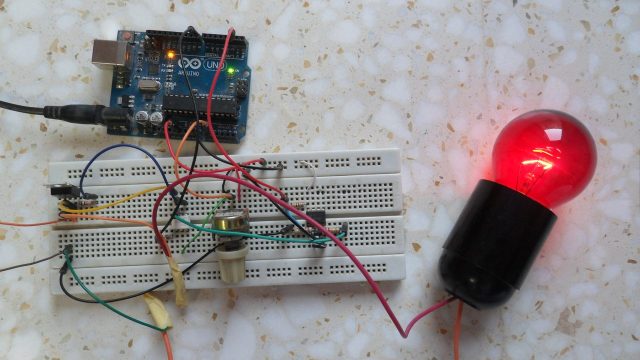 Arduino lamp brightness control
Arduino light dimmer circuit:
Project circuit schematic diagram is shown below.
Arduino lamp brightness control
Arduino light dimmer circuit:
Project circuit schematic diagram is shown below.
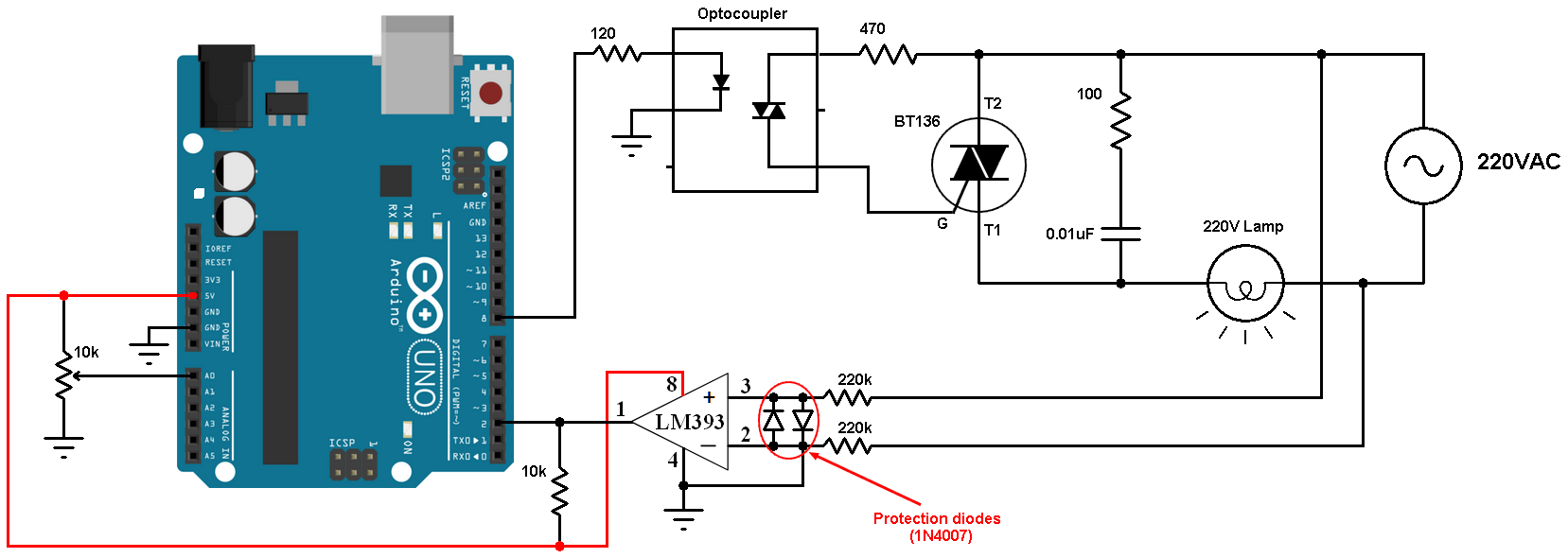 Arduino light dimmer circuit
All grounded terminals are connected together.
In this project I used the LM393 (dual comparator IC) for the zero crossing
detection, the LM339 quad comparator IC also can be used. An optocoupler
can be used for the same purpose( zero crossing detection) but I think the
comparator is much better. The two diodes which are connected between the
non-inverting input (+) and the inverting input (-) of the comparator are
used to limit the voltage across the 2 pins. The output of the LM393 (or
LM339) is an open collector, so I added a 10k ohm resistor there (between
+5V and arduino pin 2). Also the comparator chip is supplied with +5V
which comes from the Arduino board.
The optocoupler (MOC302x) is used for firing the BT136 triac, its LED is
connected to Arduino pin 8 through 120 ohm resistor. I chose the value 120
ohm in order to get a current of about 30mA (current passes through the
optocoupler LED).
The 10k potentiometer is used to control the firing angle and therefore the
brightness of the lamp.
Arduino light dimmer code:
The frequency of my AC source is 50Hz which means the period is 20ms, so
the half wave period is 10ms = 10000µs.
The resolution of Arduino ADC module is 10-bit which means the digital
value can vary between 0 and 1023.
I used Arduino interrupt (INT0 on pin 2) to detect the zero-crossing
events, so when there is a zero crossing event (falling or rising), the
Arduino interrupted and after some delay (angle alpha) it fires the triac.
/*H*****************************************************
* Arduino light brightness control (light dimmer) code
*******************************************************/
// NO INCLUDES
// =================== DEFINES =====================================
#define triac_gate 8
#define pot A0
// =================== PROTOTYPES =====================================
void ZC_detect();
// =================== VARIABLES =====================================
bool ZC = 0;
uint16_t alpha;
/*F*****************************************************
*
*******************************************************/
void
setup( void )
{
pinMode( triac_gate, OUTPUT );
digitalWrite( triac_gate, LOW );
attachInterrupt( 0, ZC_detect, CHANGE ) // ENABLE EXT INTERRUPT (INT0)
}
/*F*****************************************************
*
*******************************************************/
void
loop()
{
if( ZC )
{
if( alpha < 9500)
{
delayMicroseconds( alpha );
digitalWrite( triac_gate, HIGH );
delayMicroseconds( 200 );
digitalWrite( triac_gate, LOW );
}
ZC = 0;
alpha = (1023 - analogRead(pot) ) * 10;
if( alpha > 9500)
alpha = 9500;
}
}
/*F*****************************************************
*
*******************************************************/
void
ZC_detect()
{
ZC = 1;
}
Arduino light dimmer video:
/*H*****************************************************
* Arduino light brightness control (light dimmer) code
*******************************************************/
// NO INCLUDES
// ==================== DEFINES ====================================
#define triac_gate 8
#define pot A0
// ==================== VARIABLES ====================================
bool ZC = 0;
uint16_t alpha;
// ==================== PROTOTYPES ====================================
/*F*****************************************************
*
*******************************************************/
void
setup( void )
{
pinMode( triac_gate, OUTPUT);
digitalWrite( triac_gate, LOW);
attachInterrupt( 0, ZC_detect, CHANGE); // Enable external
interrupt (INT0)
}
/*F*****************************************************
*
*******************************************************/
void
ZC_detect()
{
ZC = 1;
}
/*F*****************************************************
*
*******************************************************/
void
loop()
{
if( ZC )
{
if( alpha < 9500)
{
delayMicroseconds( alpha );
digitalWrite( triac_gate, HIGH);
delayMicroseconds( 200 );
digitalWrite( triac_gate, LOW);
}
ZC = 0;
alpha = ( 1023 - analogRead(pot) ) * 10;
if( alpha > 9500)
alpha = 9500;
}
}
Arduino light dimmer video:
Share this:
Click to share on Facebook (Opens in new window)Click to share on X
(Opens in new window)Click to share on LinkedIn (Opens in new
window)21Click to share on Pinterest (Opens in new window)21Click to share
on Telegram (Opens in new window)
Discover more from Simple Circuit
Subscribe to get the latest posts to your email.
Type your email…
Post navigation
← Previous Post
Next Post →
Related Posts
Interfacing Arduino with 1602 LCD circuit - hd44780 Controller
Arduino LCD Example
1 Comment / Arduino Projects / By Simple Projects
Interface Arduino with DHT11 sensor and LCD circuit
Arduino interfacing with DHT11 sensor and LCD
13 Comments / Arduino Projects / By Simple Projects
Arduino uno board with DHT22 sensor and LCD
Arduino with DHT22 sensor and LCD
8 Comments / Arduino Projects / By Simple Projects
Arduino real time clock with DS1307, LCD and set buttons
Arduino real time clock with DS1307
28 Comments / Arduino Projects / By Simple Projects
22 thoughts on “220V Light dimmer with Arduino – Lamp brightness
control”
saga
December 14, 2020 at 9:05 am
excuse me, i just wanna ask about the alpha value. Can anyone explain
about the “9500” value? like how the value affect the circuit?
Thank you ^^
Reply
student
September 29, 2020 at 6:08 pm
explane for :delaymicroseconds(200);?why my lamp not stable….or
blinking…
Reply
Farai
October 10, 2020 at 1:51 pm
I have liked this project very much and i want to come up with it
but i will be thankful if someone helps me with the block diagram and a
flow chart of this project
Reply
harsh
February 13, 2020 at 7:49 am
can we replace lm393 with lm741?
Reply
Brandonn
March 30, 2021 at 9:20 pm
tried with an lm358 and it work
Reply
Ginanjar Setia
October 16, 2019 at 8:02 am
what’s the different if we didn’t use LM393? because i read from
the other blog, they didn’t use LM393
Reply
Dragos
October 13, 2019 at 6:35 am
What is the purpose of the 100 ohm resistor and 0.01uF capacitor on the
AC output? Can the circuit work without them?
Reply
Simple Projects
October 13, 2019 at 9:02 pm
That’s snubber circuit, it’s optional in this example!
Reply
Mt
October 12, 2019 at 10:57 am
hi, what is the voltage of the capacitor?
It can be 400V DC or 230V AC? Which one is correct =)
Reply
Simple Projects
October 12, 2019 at 12:39 pm
This is a ceramic capacitor (non polarized), you can easily find
ones with 600V or higher (1kV …).
If you’ve a 400V one then you can use it!
Reply
Rui
June 3, 2019 at 2:51 pm
Warning
This design may be very dangerous for people, because it does not
isolate the part of high voltage (220 V AC) of the part of low voltage (5V
DC).
The Arduino ground may be 220V relative to the AC installation ground.
Reply
Simple Projects
June 3, 2019 at 4:12 pm
When you apply 220V to 220k ohm resistor the current flows through
it will be 1mA, you may not even feel it!
Also, the system should be grounded as our PCs should be, for
example you’ll get shocked whenever you touch your PC if the outlet is
not grounded.
That circuit is for zero-crossing detection, when you say isolation
you may mean it’s better to use an optocoupler. I say the optocoupler
will not give you a precise events for the zero crossing. for example
let’s take the MOC3020 optocoupler, this device requires an input
trigger current of at least 30mA (recommended is between 30 and 50mA), the
question is what should be the value of the series resistor in order to
guarantee the triggering of the device?
A better idea is adding a step down transformer with phase shift of
0° (for example from 220V to 6V), then the output of the transformer is
connected to the comparator.
Reply
Rui
June 3, 2019 at 9:13 pm
I have use this protect circuity for a long.
https://imgur.com/a/w9qWmz9
Reply
HAP
June 3, 2019 at 8:14 am
I’ve build this circuit ,But it’s not controlling the
brightness,when pot is get to 0 lamp off and increasing the pot bulb is
on.what is the wrong ?
Reply
Simple Projects
June 3, 2019 at 8:26 am
That means the Arduino may output logic high instead of pulses on
pin 8 (triac_gate), you can check that using a simple multi-meter (or
voltmeter), you should get voltage below 5V. Or:
Make sure that you’re using an appropriate optocoupler as the one
used in the circuit (MOC3020, MOC3021 …).
Reply
cherry jane dingal
May 24, 2019 at 3:41 am
what is the wattage of the bulb you use?
Reply
Simple Projects
May 24, 2019 at 8:00 am
I think it’s 25W. You could use 60 or 100W …, but don’t use
LED bulbs because they may not be dimmable!
Reply
cherry jane dingal
May 23, 2019 at 3:00 pm
what should be done in the code if the source is 220v 60 hz??
Reply
Simple Projects
May 23, 2019 at 4:04 pm
Approximately, no thing!
Reply
samyaksshah
October 30, 2018 at 1:54 pm
In Proteus software it shows the below error:
“Not able to simulate in real time.”
So kindly help me in solving the error in software as well as in
hardware as it burns the 100 ohm resistor across the triac.
Reply
samyaksshah
October 30, 2018 at 1:52 pm
I had tried to implement this but 100 ohm resistor across the Triac
gets burnt. While increasing the resistance it is not able to switch the
bulb ON.
Reply
Md Firoj Ahmed Monty
November 25, 2019 at 7:22 am
check the capacitor across triac
Reply
Leave a Comment
Your email address will not be published. Required fields are marked *
Type here..
Name*
Email*
Website
Notify me of follow-up comments by email.
Notify me of new posts by email.
This site uses Akismet to reduce spam. Learn how your comment data is
processed.
PCBWay ad banner 300x250
Recent Posts
Isolated DC Voltage Measurement with Arduino
Interfacing Arduino with ST7735 TFT Display
Arduino Interface with ST7789 Color TFT Display
Interfacing Arduino with ILI9341 color TFT display
Isolated Zero Crossing Detection Circuit
Sponsored Links:
pcbway ad icon
Home
PIC Projects
Arduino Projects
ESP8266 Projects
MikroC Projects
CCS C Projects
MPLAB Projects
PCBWay
Contact
Home
PIC Projects
Arduino Projects
ESP8266 Projects
MikroC Projects
CCS C Projects
MPLAB Projects
PCBWay
Contact
Copyright © 2024 Simple Circuit
Home
Terms & Conditions
Privacy Policy
Contact
Scroll to Top
Arduino light dimmer circuit
All grounded terminals are connected together.
In this project I used the LM393 (dual comparator IC) for the zero crossing
detection, the LM339 quad comparator IC also can be used. An optocoupler
can be used for the same purpose( zero crossing detection) but I think the
comparator is much better. The two diodes which are connected between the
non-inverting input (+) and the inverting input (-) of the comparator are
used to limit the voltage across the 2 pins. The output of the LM393 (or
LM339) is an open collector, so I added a 10k ohm resistor there (between
+5V and arduino pin 2). Also the comparator chip is supplied with +5V
which comes from the Arduino board.
The optocoupler (MOC302x) is used for firing the BT136 triac, its LED is
connected to Arduino pin 8 through 120 ohm resistor. I chose the value 120
ohm in order to get a current of about 30mA (current passes through the
optocoupler LED).
The 10k potentiometer is used to control the firing angle and therefore the
brightness of the lamp.
Arduino light dimmer code:
The frequency of my AC source is 50Hz which means the period is 20ms, so
the half wave period is 10ms = 10000µs.
The resolution of Arduino ADC module is 10-bit which means the digital
value can vary between 0 and 1023.
I used Arduino interrupt (INT0 on pin 2) to detect the zero-crossing
events, so when there is a zero crossing event (falling or rising), the
Arduino interrupted and after some delay (angle alpha) it fires the triac.
/*H*****************************************************
* Arduino light brightness control (light dimmer) code
*******************************************************/
// NO INCLUDES
// =================== DEFINES =====================================
#define triac_gate 8
#define pot A0
// =================== PROTOTYPES =====================================
void ZC_detect();
// =================== VARIABLES =====================================
bool ZC = 0;
uint16_t alpha;
/*F*****************************************************
*
*******************************************************/
void
setup( void )
{
pinMode( triac_gate, OUTPUT );
digitalWrite( triac_gate, LOW );
attachInterrupt( 0, ZC_detect, CHANGE ) // ENABLE EXT INTERRUPT (INT0)
}
/*F*****************************************************
*
*******************************************************/
void
loop()
{
if( ZC )
{
if( alpha < 9500)
{
delayMicroseconds( alpha );
digitalWrite( triac_gate, HIGH );
delayMicroseconds( 200 );
digitalWrite( triac_gate, LOW );
}
ZC = 0;
alpha = (1023 - analogRead(pot) ) * 10;
if( alpha > 9500)
alpha = 9500;
}
}
/*F*****************************************************
*
*******************************************************/
void
ZC_detect()
{
ZC = 1;
}
Arduino light dimmer video:
/*H*****************************************************
* Arduino light brightness control (light dimmer) code
*******************************************************/
// NO INCLUDES
// ==================== DEFINES ====================================
#define triac_gate 8
#define pot A0
// ==================== VARIABLES ====================================
bool ZC = 0;
uint16_t alpha;
// ==================== PROTOTYPES ====================================
/*F*****************************************************
*
*******************************************************/
void
setup( void )
{
pinMode( triac_gate, OUTPUT);
digitalWrite( triac_gate, LOW);
attachInterrupt( 0, ZC_detect, CHANGE); // Enable external
interrupt (INT0)
}
/*F*****************************************************
*
*******************************************************/
void
ZC_detect()
{
ZC = 1;
}
/*F*****************************************************
*
*******************************************************/
void
loop()
{
if( ZC )
{
if( alpha < 9500)
{
delayMicroseconds( alpha );
digitalWrite( triac_gate, HIGH);
delayMicroseconds( 200 );
digitalWrite( triac_gate, LOW);
}
ZC = 0;
alpha = ( 1023 - analogRead(pot) ) * 10;
if( alpha > 9500)
alpha = 9500;
}
}
Arduino light dimmer video:
Share this:
Click to share on Facebook (Opens in new window)Click to share on X
(Opens in new window)Click to share on LinkedIn (Opens in new
window)21Click to share on Pinterest (Opens in new window)21Click to share
on Telegram (Opens in new window)
Discover more from Simple Circuit
Subscribe to get the latest posts to your email.
Type your email…
Post navigation
← Previous Post
Next Post →
Related Posts
Interfacing Arduino with 1602 LCD circuit - hd44780 Controller
Arduino LCD Example
1 Comment / Arduino Projects / By Simple Projects
Interface Arduino with DHT11 sensor and LCD circuit
Arduino interfacing with DHT11 sensor and LCD
13 Comments / Arduino Projects / By Simple Projects
Arduino uno board with DHT22 sensor and LCD
Arduino with DHT22 sensor and LCD
8 Comments / Arduino Projects / By Simple Projects
Arduino real time clock with DS1307, LCD and set buttons
Arduino real time clock with DS1307
28 Comments / Arduino Projects / By Simple Projects
22 thoughts on “220V Light dimmer with Arduino – Lamp brightness
control”
saga
December 14, 2020 at 9:05 am
excuse me, i just wanna ask about the alpha value. Can anyone explain
about the “9500” value? like how the value affect the circuit?
Thank you ^^
Reply
student
September 29, 2020 at 6:08 pm
explane for :delaymicroseconds(200);?why my lamp not stable….or
blinking…
Reply
Farai
October 10, 2020 at 1:51 pm
I have liked this project very much and i want to come up with it
but i will be thankful if someone helps me with the block diagram and a
flow chart of this project
Reply
harsh
February 13, 2020 at 7:49 am
can we replace lm393 with lm741?
Reply
Brandonn
March 30, 2021 at 9:20 pm
tried with an lm358 and it work
Reply
Ginanjar Setia
October 16, 2019 at 8:02 am
what’s the different if we didn’t use LM393? because i read from
the other blog, they didn’t use LM393
Reply
Dragos
October 13, 2019 at 6:35 am
What is the purpose of the 100 ohm resistor and 0.01uF capacitor on the
AC output? Can the circuit work without them?
Reply
Simple Projects
October 13, 2019 at 9:02 pm
That’s snubber circuit, it’s optional in this example!
Reply
Mt
October 12, 2019 at 10:57 am
hi, what is the voltage of the capacitor?
It can be 400V DC or 230V AC? Which one is correct =)
Reply
Simple Projects
October 12, 2019 at 12:39 pm
This is a ceramic capacitor (non polarized), you can easily find
ones with 600V or higher (1kV …).
If you’ve a 400V one then you can use it!
Reply
Rui
June 3, 2019 at 2:51 pm
Warning
This design may be very dangerous for people, because it does not
isolate the part of high voltage (220 V AC) of the part of low voltage (5V
DC).
The Arduino ground may be 220V relative to the AC installation ground.
Reply
Simple Projects
June 3, 2019 at 4:12 pm
When you apply 220V to 220k ohm resistor the current flows through
it will be 1mA, you may not even feel it!
Also, the system should be grounded as our PCs should be, for
example you’ll get shocked whenever you touch your PC if the outlet is
not grounded.
That circuit is for zero-crossing detection, when you say isolation
you may mean it’s better to use an optocoupler. I say the optocoupler
will not give you a precise events for the zero crossing. for example
let’s take the MOC3020 optocoupler, this device requires an input
trigger current of at least 30mA (recommended is between 30 and 50mA), the
question is what should be the value of the series resistor in order to
guarantee the triggering of the device?
A better idea is adding a step down transformer with phase shift of
0° (for example from 220V to 6V), then the output of the transformer is
connected to the comparator.
Reply
Rui
June 3, 2019 at 9:13 pm
I have use this protect circuity for a long.
https://imgur.com/a/w9qWmz9
Reply
HAP
June 3, 2019 at 8:14 am
I’ve build this circuit ,But it’s not controlling the
brightness,when pot is get to 0 lamp off and increasing the pot bulb is
on.what is the wrong ?
Reply
Simple Projects
June 3, 2019 at 8:26 am
That means the Arduino may output logic high instead of pulses on
pin 8 (triac_gate), you can check that using a simple multi-meter (or
voltmeter), you should get voltage below 5V. Or:
Make sure that you’re using an appropriate optocoupler as the one
used in the circuit (MOC3020, MOC3021 …).
Reply
cherry jane dingal
May 24, 2019 at 3:41 am
what is the wattage of the bulb you use?
Reply
Simple Projects
May 24, 2019 at 8:00 am
I think it’s 25W. You could use 60 or 100W …, but don’t use
LED bulbs because they may not be dimmable!
Reply
cherry jane dingal
May 23, 2019 at 3:00 pm
what should be done in the code if the source is 220v 60 hz??
Reply
Simple Projects
May 23, 2019 at 4:04 pm
Approximately, no thing!
Reply
samyaksshah
October 30, 2018 at 1:54 pm
In Proteus software it shows the below error:
“Not able to simulate in real time.”
So kindly help me in solving the error in software as well as in
hardware as it burns the 100 ohm resistor across the triac.
Reply
samyaksshah
October 30, 2018 at 1:52 pm
I had tried to implement this but 100 ohm resistor across the Triac
gets burnt. While increasing the resistance it is not able to switch the
bulb ON.
Reply
Md Firoj Ahmed Monty
November 25, 2019 at 7:22 am
check the capacitor across triac
Reply
Leave a Comment
Your email address will not be published. Required fields are marked *
Type here..
Name*
Email*
Website
Notify me of follow-up comments by email.
Notify me of new posts by email.
This site uses Akismet to reduce spam. Learn how your comment data is
processed.
PCBWay ad banner 300x250
Recent Posts
Isolated DC Voltage Measurement with Arduino
Interfacing Arduino with ST7735 TFT Display
Arduino Interface with ST7789 Color TFT Display
Interfacing Arduino with ILI9341 color TFT display
Isolated Zero Crossing Detection Circuit
Sponsored Links:
pcbway ad icon
Home
PIC Projects
Arduino Projects
ESP8266 Projects
MikroC Projects
CCS C Projects
MPLAB Projects
PCBWay
Contact
Home
PIC Projects
Arduino Projects
ESP8266 Projects
MikroC Projects
CCS C Projects
MPLAB Projects
PCBWay
Contact
Copyright © 2024 Simple Circuit
Home
Terms & Conditions
Privacy Policy
Contact
Scroll to Top